Table of Contents
Advertisement
Quick Links
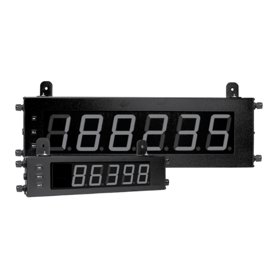
MODEL LD - LARGE DISPLAY TIMER AND CYCLE COUNTER
U L
C
C
US LISTED
US LISTED
R
IND. CONT. EQ.
E137808
GENERAL DESCRIPTION
The Large Display Timer and Cycle Counter is a versatile display that
functions as an Elapsed Timer or Preset Timer, with full-featured user
programmability. The meter includes a built-in Cycle Counter, relay output and
serial communications capability. The 6 digit displays are available in either
2.25" or 4" high red LED digits with adjustable display intensity. The 2.25" high
models are readable up to 130 feet. The 4" high models are readable up to 180
feet. Both versions are constructed of a NEMA 4X/IP65 enclosure in light
weight aluminum.
The Timer has two signal inputs and eight input operating modes. These
modes provide level active or edge triggered start/stop operation. The Timer
features 18 selectable timer ranges to cover a wide variety of timing applications.
The built-in Cycle Counter can be linked to timer operation to count timing
cycles, or function as a totally independent counter, accepting count speeds up
to 500 Hz. The display can be toggled either manually or automatically between
the Timer and Counter values.
In addition to the Timer/Counter inputs, a programmable User Input is
provided to perform a variety of meter functions. DIP switches are used to
configure the inputs for current sinking (active low) or current sourcing (active
high) operation.
The Setpoint Output can be assigned to the Timer or Counter value, and
configured to suit a variety of control and alarm requirements. The meter also
includes RS232 or RS485 serial communications.
CAUTION: Risk of Danger.
Read complete instructions prior to
installation and operation of the unit.
DIMENSIONS In inches (mm)
CAUTION: Risk of electric shock.
2.25" or 4" HIGH RED LED DIGITS
6-DIGIT BI-DIRECTIONAL TIMING CAPABILITY
5-DIGIT CYCLE COUNTING CAPABILITY
SELECTABLE TIMER RANGES AND OPERATING MODES
ELAPSED TIMER AND PRESET TIMER FUNCTIONALITY
SERIAL COMMUNICATIONS (RS232 or RS485)
PROGRAMMABLE USER INPUT
UNIVERSALLY POWERED
5 AMP FORM C RELAY OUTPUT
ALUMINUM NEMA 4X CASE CONSTRUCTION
SAFETY SUMMARY
All safety related regulations, local codes and instructions that appear in this
document or on equipment must be observed to ensure personal safety and to
prevent damage to either the device or equipment connected to it.
Do not use these products to replace proper safety interlocking. No software-
based device (or any other solid-state device) should ever be designed to be
responsible for the maintenance of personnel safety or consequential equipment
not equipped with safeguards. Red Lion disclaims any responsibility for
damages, either direct or consequential, that result from the use of this
equipment in a manner not specified.
The protective conductor terminal is bonded to conductive
parts of the equipment for safety purposes and must be
connected to an external protective earthing system.
SPECIFICATIONS
1. DISPLAY: 2.25" (57 mm) or 4" (101 mm) intensity adjustable Red LED
2. POWER REQUIREMENTS:
AC POWER: 50 to 250 VAC 50/60 Hz, 26 VA
DC POWER: 21.6 to 250 VDC, 11 W
DC Out: +24 VDC @ 100 mA if input voltage is greater than 50 VAC/VDC
+24 VDC @ 50 mA if input voltage is less than 50 VDC
Isolation: 2300 V
for 1 min. to all inputs and outputs
RMS
3. TIMER DISPLAY: 6-digits
Display Range: 0 to 999999
Overflow/Underflow Indication: Display flashes "
Minimum Digit Resolution: 0.001 Sec.
Maximum Single Digit Resolution: 1 Hr.
Timing Accuracy: ±0.01%
4. CYCLE COUNTER DISPLAY: 5-digits, may be disabled if not used
Display Designator: "
" to the left side of the display
1
Bulletin No. LDT-H
Drawing No. LP0634
Released 08/21
"
PART
X (Length)
Y (Height)
NUMBER
LD2T06P0 16 (406.4) 4 (101.6)
LD4T06P0 26 (660.4) 7.875 (200) 22 (558.8)
Z (Center)
12 (304.8)
Advertisement
Table of Contents

Related Manuals for red lion LD


Summary of Contents for red lion LD
- Page 1 Bulletin No. LDT-H Drawing No. LP0634 Released 08/21 MODEL LD - LARGE DISPLAY TIMER AND CYCLE COUNTER 2.25" or 4" HIGH RED LED DIGITS 6-DIGIT BI-DIRECTIONAL TIMING CAPABILITY 5-DIGIT CYCLE COUNTING CAPABILITY SELECTABLE TIMER RANGES AND OPERATING MODES ...
-
Page 2: Ordering Information
4" High 6-Digit Red LED Timer/Cycle Counter w/ Relay Output & LD4T06P0 RS232/RS485 Serial Communications LD Plug Cord Grip Plug for LD models * LDPLUG00 * Required to maintain Type 4X/IP65 specification, if end plate cord grip does not have cable installed. 1.0 I... -
Page 3: Emc Installation Guidelines
Visit RLC’s web site at http://www.redlion.net/emi for more information on EMI guidelines, Safety and CE issues as they relate to Red Lion Controls 4. Long cable runs are more susceptible to EMI pickup than short cable runs. -
Page 4: Wiring Overview
0.181" (4.6 mm) to 0.312" (7.9 mm). If the cord grip is unused, remove it and replace with the LD cord grip plug (part # LDPLUG00). The LDPLUG00 must be ordered separately. -
Page 5: Input Wiring
RXD line to a space condition (logic 0). The meter then as 10M baud (the LD is limited to 38.4k baud). The same pair of wires is used suspends transmission until the RXD line is released by the receiving device. - Page 6 4.0 r evIeWIng the ront anel eys anD IsPlay DISPLAY MODE OPERATION PROGRAMMING MODE OPERATION Access Programming Mode Store selected parameter and index to next parameter Advance through selection list/select digit position in SEL Select display (Timer or Cycle Counter) parameter value RST...
- Page 7 5.1 MoDUle 1 - t IMer nPUt araMeters PARAMETER MENU 1-INP rAN6E INP OP FILtEr t-dir t-Strt t-StOP FLASH t P-UP r P-UP USrINP USrASN Timer Timer Input Timer Input Timing Timer Start Timer Stop Flash Timer Timer Run Timer Reset User Input User Input...
-
Page 8: Parameter Menu
TIMER RESET AT POWER-UP USER INPUT FUNCTION (Cont’d) DISPLAY MODE DESCRIPTION Inhibit timing or counting for the Inhibit selected value(s). Display Intensity Level Increase intensity one level The Timer can be programmed to Reset at each meter power-up. ... - Page 9 5.3 MoDUle 3 - D IsPlay anD ront anel araMeters PARAMETER MENU 3-dSP SEL-En rSt-En ScroLL d-LEV CodE FACSEt Front Panel Front Panel Display Scroll Display Programming Load Factory Display Reset Enable Enable Intensity Security Default Select Level Code Settings the Setpoint values and Timer Stop value to be modified, but allows direct FRONT PANEL DISPLAY SELECT ENABLE (SEL...
- Page 10 5.4 MoDUle 4 - s etPoInt UtPUt araMeters PARAMETER MENU 4-SPt SP-ASN SP-ACt SP-ON SP-OFF O-tOUt StOP-t AUtO-r OrSt-r O P-UP Setpoint Setpoint Setpoint On Setpoint O Setpoint Stop Timer Setpoint Timer/Counter Setpoint Assignment Output Action Output Output Reset Auto Reset Output Time-out...
- Page 11 5.5 MoDUle 5 - s erIal oMMUnIcatIons araMeters PARAMETER MENU 5-SEr bAUd dAtA PAritY Addr Abbr Pr-OPt Baud Rate Data Bit Parity Bit Meter Abbreviated Print Address Printing Options Module 5 is the programming module for the Serial Communications Parameters.
- Page 12 Sending Serial Commands and Data Register Identification Chart When sending commands to the meter, a string containing at least one command character must be constructed. A command string consists of a Value Applicable MNEMONIC Transmit Details (T and V) command character, a value identifier, numerical data (if writing data to the Description Commands meter) followed by a command terminator character, * or $.
- Page 13 Given this limitation, the parity bit is often ignored by the Data is transmitted one byte at a time with a variable idle period between receiving device. The LD Timer ignores the parity bit of incoming data and sets ∞...
- Page 14 This page intentionally left blank.
- Page 15 PrograMMIng QUIcK overvIeW...
-
Page 16: Limited Warranty
COPYRIGHT ©2021 Red Lion Controls, Inc. All rights reserved. Red Lion and the Red Lion logo are trademarks of Red Lion Controls, Inc. All other company and product names are trademarks of their respective owners. LIMITED WARRANTY (a) Red Lion Controls Inc. (the “Company”) warrants that all Products shall be free from defects in material and workmanship under normal use for the period of time provided in “Statement of Warranty Periods”...
Need help?
Do you have a question about the LD and is the answer not in the manual?
Questions and answers