Table of Contents
Advertisement
Quick Links
One Technology Way • P.O. Box 9106 • Norwood, MA 02062-9106, U.S.A. • Tel: 781.329.4700 • Fax: 781.461.3113 • www.analog.com
Evaluating the
FEATURES
Supports the detection of UART
UDP transfer capability
ADPD144RI
full configuration
Register level
High level
Graph view
Time graph
Frequency graph
EVALUATION KIT CONTENTS
EVAL-ADPD144RIZ-SF evaluation boards
ADDITIONAL EQUIPMENT NEEDED
PC running Windows® 7 or Windows 10 operating system
EVAL-ADPDUCZ
microcontroller board
ONLINE RESOURCES
ADPD144RI
data sheet
Applications Wavetool software package
PLEASE SEE THE LAST PAGE FOR AN IMPORTANT
WARNING AND LEGAL TERMS AND CONDITIONS.
ADPD144RI
PPG Optical Sensor Module with Integrated Red/IR
Emitters and AFE
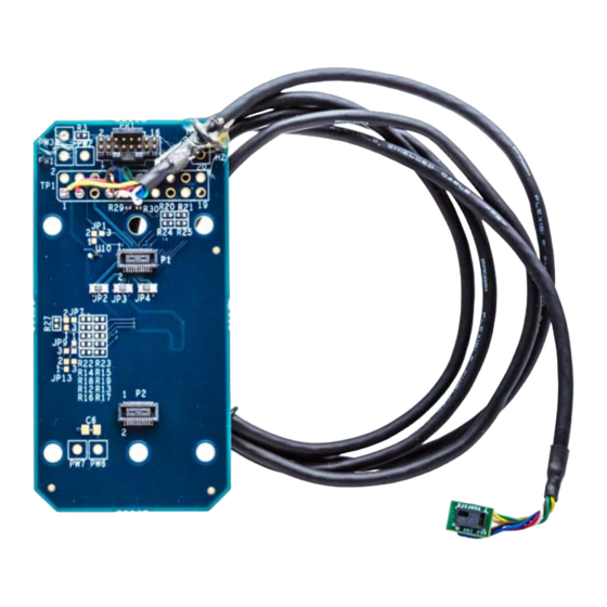
EVAL-ADPD144RIZ-SF EVALUATION KIT PHOTOGRAPH
EVAL-ADPD144RIZ-SF
GENERAL DESCRIPTION
The EVAL-ADPD144RIZ-SF provides users with a means of
evaluating the ADPD144RI, a complete photometric system
designed to measure optical signals from ambient light and
from synchronous, reflected light emitting diode (LED) pulses.
The evaluation system includes the Applications Wavetool
graphical user interface (GUI), which provides users with low
level and high level configurability; real-time frequency and
time domain analysis; and a user datagram protocol (UDP)
transfer capability so that the evaluation board can easily
connect to the user development system.
The EVAL-ADPD144RIZ-SF is a multiboard evaluation kit
consisting of an adapter board and a sensor board connected
by a 3 foot cable. The adapter board connects to the
ADPDUCZ
microcontroller board through a ribbon cable.
The evaluation board is optimized for ear-based photo-
plethysmography (PPG) measurements.
For additional information on the functionality of the
ADPD144RI, see the
with this user guide when using the EVAL-ADPD144RIZ-SF.
Figure 1.
Rev. 0 | Page 1 of 10
User Guide
ADPD144RI
data sheet in conjunction
UG-1272
EVAL-
Advertisement
Table of Contents

Subscribe to Our Youtube Channel
Related Manuals for Analog Devices EVAL-ADPD144RIZ-SF


Summary of Contents for Analog Devices EVAL-ADPD144RIZ-SF
-
Page 1: Features
PPG Optical Sensor Module with Integrated Red/IR Emitters and AFE FEATURES GENERAL DESCRIPTION Supports the detection of UART The EVAL-ADPD144RIZ-SF provides users with a means of UDP transfer capability evaluating the ADPD144RI, a complete photometric system ADPD144RI full configuration designed to measure optical signals from ambient light and Register level from synchronous, reflected light emitting diode (LED) pulses. -
Page 2: Table Of Contents
Acquiring Data...................4 Online Resources ................1 Running the Applications Wavetool ..........4 General Description ................. 1 USB UART Connection..............4 EVAL-ADPD144RIZ-SF Evaluation Kit Photograph ....1 Selecting the Proper View ............4 Revision History ................2 Load Configuration ..............4 Getting Started .................. 3 Optimizing and Running the ADPD144RI .......5... -
Page 3: Getting Started
CHECKING THE USB SERIAL CONNECTION IN WINDOWS Download the Applications Wavetool software package from the EVAL-ADPD144RIZ-SF product page. Unzip the folder and Ensure that the communications port (COM port) driver is run the Applications Wavetool executable file. Follow the installed correctly. To verify proper installation, go to Control prompts, beginning with the Applications Wavetool Setup Panel >... -
Page 4: Acquiring Data
PPG To start the Applications Wavetool, navigate to the Start measurements. Click the ADPD Device data view (see Figure 6) menu > Analog Devices > ApplicationsWaveTool and click to open a window that allows the user to run the ADPD144RI ApplicationsWavetool. -
Page 5: Optimizing And Running The Adpd144Ri
EVAL-ADPD144RIZ-SF User Guide UG-1272 analog front end (AFE) timing. Another option is to use OPTIMIZING AND RUNNING THE ADPD144RI different operating modes that can be more optimal for a After the configuration file is loaded, the settings can be further specific set of conditions, such as using float mode for a low optimized using the ADPD Config window shown in Figure 7. -
Page 6: Evaluation Board Schematics And Artwork
UG-1272 EVAL-ADPD144RIZ-SF User Guide EVALUATION BOARD SCHEMATICS AND ARTWORK Figure 9. EVAL-ADPD144RIZ-SF BR-048862 Schematic Rev. 0 | Page 6 of 10... - Page 7 VLED GND_LOCAL 1µF GND_LOCAL GND_LOCAL VREF 10kΩ 10kΩ SPARE LED1/DNC SPARE LED2/DNC 1µF ADPD144RI-ACEZ GND_LOCAL GND_LOCAL Figure 10. EVAL-ADPD144RIZ-SF BR-048911 Schematic Figure 11. EVAL-ADPD144RIZ-SF BR-048911 Primary Layer Figure 12. EVAL-ADPD144RIZ-SF BR-048911 Secondary Layer Rev. 0 | Page 7 of 10...
- Page 8 UG-1272 EVAL-ADPD144RIZ-SF User Guide Figure 13. EVAL-ADPD144RIZ-SF BR-048862 Primary Layer Figure 14. EVAL-ADPD144RIZ-SF BR-048862 Secondary Layer Rev. 0 | Page 8 of 10...
- Page 9 EVAL-ADPD144RIZ-SF User Guide UG-1272 Figure 15. EVAL-ADPD144RIZ-SF Connected to the EVAL-ADPDUCZ Microcontroller Board Rev. 0 | Page 9 of 10...
- Page 10 (“Agreement”) unless you have purchased the Evaluation Board, in which case the Analog Devices Standard Terms and Conditions of Sale shall govern. Do not use the Evaluation Board until you have read and agreed to the Agreement. Your use of the Evaluation Board shall signify your acceptance of the Agreement. This Agreement is made by and between you (“Customer”) and Analog Devices, Inc.
Need help?
Do you have a question about the EVAL-ADPD144RIZ-SF and is the answer not in the manual?
Questions and answers