Table of Contents
Advertisement
Quick Links
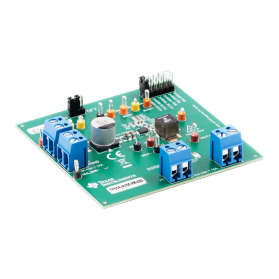
Using the TPS54JA20EVM-023 12-A, Buck Converter
This user's guide contains information for the TPS54JA20EVM-023 evaluation module (EVM) as well as
for the TPS54JA20 DC/DC converter. Also included are the performance specifications, the schematic,
and the list of materials for the TPS54JA20EVM.
...................................................................................................................
1
1.1
1.2
1.3
2
2.1
2.2
2.3
2.4
2.5
2.6
2.7
2.8
3
3.1
3.2
3.3
1
2
3
4
5
6
7
TPS54JA20 Load Regulation
8
9
TPS54JA20 Load Transient Response
10
11
12
13
14
15
16
17
18
SLVUBO0A - March 2020 - Revised May 2020
..........................................................................................................
.........................................................................................................
.....................................................................................................
..........................................................................................
.................................................................................................
.............................................................................................................
.....................................................................................................
.....................................................................................................
..............................................................................................
............................................................................................
.......................................................................................................
................................................................................
..........................................................................................................
....................................................................................................
...............................................................................................................
.............................................................................................................
...................................................................................
..................................................................................
...................................................................................
..............................................................................................
..............................................................................................
...................................................................................
...................................................................................
.....................................................................................................
....................................................................................
..................................................................................
................................................................................
...................................................................................
.......................................................................................
...............................................................................
...............................................................................
Copyright © 2020, Texas Instruments Incorporated
SLVUBO0A - March 2020 - Revised May 2020
Evaluation Module
Contents
............................................................................
List of Figures
.....................................................................
..................................................................
User's Guide
2
2
3
3
5
5
5
6
8
9
10
11
12
13
14
15
16
2
6
6
7
7
8
8
9
9
10
11
11
11
12
12
17
17
18
1
Advertisement
Table of Contents

Subscribe to Our Youtube Channel
Related Manuals for Texas Instruments TPS54JA20EVM-023


Summary of Contents for Texas Instruments TPS54JA20EVM-023
-
Page 1: Table Of Contents
Using the TPS54JA20EVM-023 12-A, Buck Converter Evaluation Module This user’s guide contains information for the TPS54JA20EVM-023 evaluation module (EVM) as well as for the TPS54JA20 DC/DC converter. Also included are the performance specifications, the schematic, and the list of materials for the TPS54JA20EVM. -
Page 2: Introduction
= 4 V to 16 V 0 A to 12 A Figure 1. Safety Warnings Using the TPS54JA20EVM-023 12-A, Buck Converter Evaluation Module SLVUBO0A – March 2020 – Revised May 2020 Submit Documentation Feedback Copyright © 2020, Texas Instruments Incorporated... -
Page 3: Performance Specification Summary
The value of R6 and R7 for a specific output voltage can be calculated using Equation INTREF FB HS FB LS INTREF = 0.9V INTREF FB_HS = 10kΩ FB_LS SLVUBO0A – March 2020 – Revised May 2020 Using the TPS54JA20EVM-023 12-A, Buck Converter Evaluation Module Submit Documentation Feedback Copyright © 2020, Texas Instruments Incorporated... - Page 4 The undervoltage lockout (UVLO) can be adjusted externally using R2 and R9. See the TPS54JA20 Data Sheet to get detailed instructions for setting the external UVLO. Using the TPS54JA20EVM-023 12-A, Buck Converter Evaluation Module SLVUBO0A – March 2020 – Revised May 2020 Submit Documentation Feedback Copyright ©...
-
Page 5: Test Setup And Results
3. Apply appropriate VIN voltage to the VIN and PGND terminals at J1 and J2. SLVUBO0A – March 2020 – Revised May 2020 Using the TPS54JA20EVM-023 12-A, Buck Converter Evaluation Module Submit Documentation Feedback Copyright © 2020, Texas Instruments Incorporated... -
Page 6: Efficiency
3.3-V VCC FCCM 5-V VCC Output Current (A) D020 Figure 3. TPS54JA20 Efficiency Plot: Vcc Range Using the TPS54JA20EVM-023 12-A, Buck Converter Evaluation Module SLVUBO0A – March 2020 – Revised May 2020 Submit Documentation Feedback Copyright © 2020, Texas Instruments Incorporated... -
Page 7: Tps54Ja20 Efficiency Plot: Skip Mode
800 nH Skip Output Current (A) D021 Figure 5. TPS54JA20 Efficiency Plot: FCCM and Skip Mode SLVUBO0A – March 2020 – Revised May 2020 Using the TPS54JA20EVM-023 12-A, Buck Converter Evaluation Module Submit Documentation Feedback Copyright © 2020, Texas Instruments Incorporated... -
Page 8: Load Regulation
Skip 2.487 VCC = Int 2.484 Output Current (A) D026 Figure 7. TPS54JA20 Load Regulation Using the TPS54JA20EVM-023 12-A, Buck Converter Evaluation Module SLVUBO0A – March 2020 – Revised May 2020 Submit Documentation Feedback Copyright © 2020, Texas Instruments Incorporated... -
Page 9: Load Transients
Figure 8. TPS54JA20 Load Transient Response Figure 9. TPS54JA20 Load Transient Response SLVUBO0A – March 2020 – Revised May 2020 Using the TPS54JA20EVM-023 12-A, Buck Converter Evaluation Module Submit Documentation Feedback Copyright © 2020, Texas Instruments Incorporated... -
Page 10: Loop Characteristics
20000 30000 50000 100000 200000 300000 500000 1000000 Frequency (Hz) D018 Figure 10. TPS54JA20 Bode Plot Using the TPS54JA20EVM-023 12-A, Buck Converter Evaluation Module SLVUBO0A – March 2020 – Revised May 2020 Submit Documentation Feedback Copyright © 2020, Texas Instruments Incorporated... -
Page 11: Output Voltage Ripple
Figure 12. TPS54JA20 Output Ripple, 12-A Load Figure 13. TPS54JA20 Output Ripple, Skip Mode, 10mA Load SLVUBO0A – March 2020 – Revised May 2020 Using the TPS54JA20EVM-023 12-A, Buck Converter Evaluation Module Submit Documentation Feedback Copyright © 2020, Texas Instruments Incorporated... -
Page 12: Powering Up
Figure 15 shows the TPS54JA20EVM shutdown. The input voltage for these plots is 12 V. Figure 15. TPS54JA20 EN Shutdown, 12A Load Using the TPS54JA20EVM-023 12-A, Buck Converter Evaluation Module SLVUBO0A – March 2020 – Revised May 2020 Submit Documentation Feedback... -
Page 13: Schematic, List Of Materials, And Layout
This section provides a schematic, a description of the TPS54JA20EVM board layout, and layer illustrations. SLVUBO0A – March 2020 – Revised May 2020 Using the TPS54JA20EVM-023 12-A, Buck Converter Evaluation Module Submit Documentation Feedback Copyright © 2020, Texas Instruments Incorporated... -
Page 14: Schematic
Schematic, List of Materials, and Layout www.ti.com Schematic The following image illustrates the schematic for the TPS54JA20EVM. Using the TPS54JA20EVM-023 12-A, Buck Converter Evaluation Module SLVUBO0A – March 2020 – Revised May 2020 Submit Documentation Feedback Copyright © 2020, Texas Instruments Incorporated... -
Page 15: List Of Materials
Vishay-Dale 4-V to 16-V Input, 12-A Single Synchronous Step-Down TPS54JA20RWWT Texas Instruments Converter, RWW0021A (VQFN-HR-21) SLVUBO0A – March 2020 – Revised May 2020 Using the TPS54JA20EVM-023 12-A, Buck Converter Evaluation Module Submit Documentation Feedback Copyright © 2020, Texas Instruments Incorporated... -
Page 16: Layout
Critical analog circuits that are noise sensitive are terminated to the quiet analog ground island on the top layer. Using the TPS54JA20EVM-023 12-A, Buck Converter Evaluation Module SLVUBO0A – March 2020 – Revised May 2020 Submit Documentation Feedback... -
Page 17: Tps54Ja20Evm Top-Side Layout
Schematic, List of Materials, and Layout www.ti.com Figure 16. TPS54JA20EVM Top-Side Layout Figure 17. TPS54JA20EVM Internal Layer-1 Layout SLVUBO0A – March 2020 – Revised May 2020 Using the TPS54JA20EVM-023 12-A, Buck Converter Evaluation Module Submit Documentation Feedback Copyright © 2020, Texas Instruments Incorporated... -
Page 18: Tps54Ja20Evm Internal Layer-2 Layout
Schematic, List of Materials, and Layout www.ti.com Figure 18. TPS54JA20EVM Internal Layer-2 Layout Figure 19. TPS54JA20EVM Bottom-Side Layout Using the TPS54JA20EVM-023 12-A, Buck Converter Evaluation Module SLVUBO0A – March 2020 – Revised May 2020 Submit Documentation Feedback Copyright © 2020, Texas Instruments Incorporated... - Page 19 NOTE: Page numbers for previous revisions may differ from page numbers in the current version. Changes from Original (March 2020) to A Revision ....................... Page ............... • Changed marketing status from select disclosure to catalog. SLVUBO0A – March 2020 – Revised May 2020 Revision History Submit Documentation Feedback Copyright © 2020, Texas Instruments Incorporated...
- Page 20 STANDARD TERMS FOR EVALUATION MODULES Delivery: TI delivers TI evaluation boards, kits, or modules, including any accompanying demonstration software, components, and/or documentation which may be provided together or separately (collectively, an “EVM” or “EVMs”) to the User (“User”) in accordance with the terms set forth herein.
- Page 21 www.ti.com Regulatory Notices: 3.1 United States 3.1.1 Notice applicable to EVMs not FCC-Approved: FCC NOTICE: This kit is designed to allow product developers to evaluate electronic components, circuitry, or software associated with the kit to determine whether to incorporate such items in a finished product and software developers to write software applications for use with the end product.
- Page 22 www.ti.com Concernant les EVMs avec antennes détachables Conformément à la réglementation d'Industrie Canada, le présent émetteur radio peut fonctionner avec une antenne d'un type et d'un gain maximal (ou inférieur) approuvé pour l'émetteur par Industrie Canada. Dans le but de réduire les risques de brouillage radioélectrique à...
- Page 23 www.ti.com EVM Use Restrictions and Warnings: 4.1 EVMS ARE NOT FOR USE IN FUNCTIONAL SAFETY AND/OR SAFETY CRITICAL EVALUATIONS, INCLUDING BUT NOT LIMITED TO EVALUATIONS OF LIFE SUPPORT APPLICATIONS. 4.2 User must read and apply the user guide and other available documentation provided by TI regarding the EVM prior to handling or using the EVM, including without limitation any warning or restriction notices.
- Page 24 Notwithstanding the foregoing, any judgment may be enforced in any United States or foreign court, and TI may seek injunctive relief in any United States or foreign court. Mailing Address: Texas Instruments, Post Office Box 655303, Dallas, Texas 75265 Copyright © 2019, Texas Instruments Incorporated...
- Page 25 TI products. TI’s provision of these resources does not expand or otherwise alter TI’s applicable warranties or warranty disclaimers for TI products. Mailing Address: Texas Instruments, Post Office Box 655303, Dallas, Texas 75265 Copyright © 2020, Texas Instruments Incorporated...
Need help?
Do you have a question about the TPS54JA20EVM-023 and is the answer not in the manual?
Questions and answers