Table of Contents
Advertisement
Quick Links
www.ti.com
User's Guide
TPS549D22 SWIFT™ Step-Down Converter Evaluation
Module User's Guide
This user's guide describes the characteristics, operation, and use of the TPS549D22 Evaluation Module
(EVM). The user's guide includes test information, descriptions, and results. A complete schematic diagram,
printed-circuit board layouts, and bill of materials are also included in this document. Throughout this user's
guide, the abbreviations EVM, TPS549D22EVM, and the term evaluation module are synonymous with the
TPS549D22EVM-784, unless otherwise noted.
1
Introduction.............................................................................................................................................................................3
2 Description..............................................................................................................................................................................
2.1 Typical End-User Applications...........................................................................................................................................
2.2 EVM Features....................................................................................................................................................................
4
Schematic................................................................................................................................................................................5
Setup................................................................................................................................................................................6
5.1 Test and Configuration Software........................................................................................................................................
6 Test Equipment.......................................................................................................................................................................
7
PWR-784EVM...........................................................................................................................................................................8
8 List of Test Points, Jumpers, and Switch...........................................................................................................................
9 EVM Configuration Using the Fusion GUI..........................................................................................................................
10 Test Procedure....................................................................................................................................................................
10.2
Efficiency........................................................................................................................................................................12
10.3 Equipment Shutdown.....................................................................................................................................................
11.1 Efficiency........................................................................................................................................................................
11.2 Load Regulation.............................................................................................................................................................
Regulation...............................................................................................................................................................14
11.4 Transient Response.......................................................................................................................................................
Ripple..................................................................................................................................................................19
11.6 Control On......................................................................................................................................................................
11.7 Control Off......................................................................................................................................................................
11.8 Thermal Image...............................................................................................................................................................
GUI...........................................................................................................................................................................23
13 EVM Assembly Drawing and PCB Layout........................................................................................................................
14 List of Materials..................................................................................................................................................................
15 Revision History.................................................................................................................................................................
Figure 4-1. PWR-784EVM Schematic.........................................................................................................................................
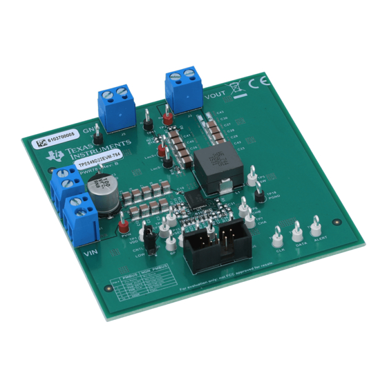
Figure 7-1. PWR-784EVM Overview...........................................................................................................................................
Figure 7-2. Tip and Barrel Measurement.....................................................................................................................................
Figure 11-1. Efficiency of 1-V Output vs Load...........................................................................................................................
Figure 11-2. Load Regulation of 1-V Output..............................................................................................................................
Figure 11-3. Line Regulation of 1-V Output...............................................................................................................................
Step-Up = 0.6 V to 1.2 V at 0
OUT
SLUUBG4A - JULY 2016 - REVISED AUGUST 2021
Submit Document Feedback
ABSTRACT
Table of Contents
Specifications.........................................................................................................................4
Procedure......................................................................................................12
Curves.....................................................................................................13
List of Figures
Adapter...............................................................................................................................9
A........................................................................................................14
TPS549D22 SWIFT™ Step-Down Converter Evaluation Module User's Guide
Copyright © 2021 Texas Instruments Incorporated
Table of Contents
3
3
3
6
7
10
11
12
12
13
13
19
20
21
22
35
40
42
5
8
8
13
13
14
1
Advertisement
Table of Contents

Related Manuals for Texas Instruments TPS549D22


Summary of Contents for Texas Instruments TPS549D22
-
Page 1: Table Of Contents
Module User's Guide ABSTRACT This user's guide describes the characteristics, operation, and use of the TPS549D22 Evaluation Module (EVM). The user's guide includes test information, descriptions, and results. A complete schematic diagram, printed-circuit board layouts, and bill of materials are also included in this document. Throughout this user's guide, the abbreviations EVM, TPS549D22EVM, and the term evaluation module are synonymous with the TPS549D22EVM-784, unless otherwise noted. - Page 2 ™ is a trademark of SMIF, Inc.. All trademarks are the property of their respective owners. TPS549D22 SWIFT™ Step-Down Converter Evaluation Module User's Guide SLUUBG4A – JULY 2016 – REVISED AUGUST 2021 Submit Document Feedback Copyright © 2021 Texas Instruments Incorporated...
-
Page 3: Introduction
40-A current output. 2 Description The PWR784EVM is designed as a single output DC-DC converter that demonstrates the TPS549D22 in a typical low-voltage application while providing a number of test points to evaluate the performance. It uses a nominal 12-V input bus to produce a regulated 1-V output at up to 40-A load current. -
Page 4: Evm Electrical Performance Specifications
= 12 V, I = 18 A, F = 650 kHz Operating temperature °C oper TPS549D22 SWIFT™ Step-Down Converter Evaluation Module User's Guide SLUUBG4A – JULY 2016 – REVISED AUGUST 2021 Submit Document Feedback Copyright © 2021 Texas Instruments Incorporated... -
Page 5: Schematic
FSEL AGND 37.4k 42.2k Copyright © 2016, Texas Instruments Incorporated AGND Figure 4-1. PWR-784EVM Schematic SLUUBG4A – JULY 2016 – REVISED AUGUST 2021 TPS549D22 SWIFT™ Step-Down Converter Evaluation Module User's Guide Submit Document Feedback Copyright © 2021 Texas Instruments Incorporated... -
Page 6: Test Setup
The Fusion Digital Power Designer is the graphical user interface (GUI) used to configure and monitor the Texas Instruments TPS549D22 power converter installed on this evaluation module. The application uses the PMBus protocol to communicate with the controller over serial bus by way of a TI USB adapter. This adapter can be purchased at http://www.ti.com/tool/usb-to-gpio. -
Page 7: Test Equipment
This recommended wire gauge and length should achieve a voltage drop of no more than 0.2 V at the maximum 40-A load. SLUUBG4A – JULY 2016 – REVISED AUGUST 2021 TPS549D22 SWIFT™ Step-Down Converter Evaluation Module User's Guide Submit Document Feedback Copyright © 2021 Texas Instruments Incorporated... -
Page 8: Pwr-784Evm
Metal Ground Barrel Probe Tip and Barrel V Ripple Measurement Figure 7-2. Tip and Barrel Measurement TPS549D22 SWIFT™ Step-Down Converter Evaluation Module User's Guide SLUUBG4A – JULY 2016 – REVISED AUGUST 2021 Submit Document Feedback Copyright © 2021 Texas Instruments Incorporated... -
Page 9: Figure 7-3. Evm And Usb Interface Adapter
PWR-784EVM Figure 7-3. EVM and USB Interface Adapter SLUUBG4A – JULY 2016 – REVISED AUGUST 2021 TPS549D22 SWIFT™ Step-Down Converter Evaluation Module User's Guide Submit Document Feedback Copyright © 2021 Texas Instruments Incorporated... -
Page 10: List Of Test Points, Jumpers, And Switch
SMB_ALRT# Alert output for the PMBus interface. 2-pin jumper CNTL Shunts control pin to GND TPS549D22 SWIFT™ Step-Down Converter Evaluation Module User's Guide SLUUBG4A – JULY 2016 – REVISED AUGUST 2021 Submit Document Feedback Copyright © 2021 Texas Instruments Incorporated... -
Page 11: Evm Configuration Using The Fusion Gui
Digital Power Designer software can be used for reconfiguration. It is necessary to have input voltage applied to the EVM prior to launching the software so that the TPS549D22 installed is active and able to respond to the GUI and the GUI can recognize the device. -
Page 12: Test Procedure
2. Reduce input voltage to 0 V. 3. Shut down the external fan if in use. 4. Shut down equipment. TPS549D22 SWIFT™ Step-Down Converter Evaluation Module User's Guide SLUUBG4A – JULY 2016 – REVISED AUGUST 2021 Submit Document Feedback Copyright © 2021 Texas Instruments Incorporated... -
Page 13: Performance Data And Typical Characteristic Curves
1.005 0.995 12 V 16 V 0.99 D002 Figure 11-2. Load Regulation of 1-V Output SLUUBG4A – JULY 2016 – REVISED AUGUST 2021 TPS549D22 SWIFT™ Step-Down Converter Evaluation Module User's Guide Submit Document Feedback Copyright © 2021 Texas Instruments Incorporated... -
Page 14: Line Regulation
Figure 11-3. Line Regulation of 1-V Output Figure 11-4. PMBus V Step-Up = 0.6 V to 1.2 V at 0 A TPS549D22 SWIFT™ Step-Down Converter Evaluation Module User's Guide SLUUBG4A – JULY 2016 – REVISED AUGUST 2021 Submit Document Feedback... -
Page 15: Figure 11-5. Pmbus
Performance Data and Typical Characteristic Curves Figure 11-5. PMBus V Step-Down = 1.2 V to 0.6 V at 0 A SLUUBG4A – JULY 2016 – REVISED AUGUST 2021 TPS549D22 SWIFT™ Step-Down Converter Evaluation Module User's Guide Submit Document Feedback Copyright © 2021 Texas Instruments Incorporated... -
Page 16: Out A
Figure 11-6. PMBus V Step-Up = 0.6 V to 1.2 V at 40 A TPS549D22 SWIFT™ Step-Down Converter Evaluation Module User's Guide SLUUBG4A – JULY 2016 – REVISED AUGUST 2021 Submit Document Feedback Copyright © 2021 Texas Instruments Incorporated... -
Page 17: Figure 11-7. Pmbus Vout Step-Down = 1.2 V To 0.6 V At 40 A
Performance Data and Typical Characteristic Curves Figure 11-7. PMBus V Step-Down = 1.2 V to 0.6 V at 40 A SLUUBG4A – JULY 2016 – REVISED AUGUST 2021 TPS549D22 SWIFT™ Step-Down Converter Evaluation Module User's Guide Submit Document Feedback Copyright © 2021 Texas Instruments Incorporated... -
Page 18: Figure 11-8. Pmbus Multiple Commands
Performance Data and Typical Characteristic Curves www.ti.com Figure 11-8. PMBUS Multiple Commands TPS549D22 SWIFT™ Step-Down Converter Evaluation Module User's Guide SLUUBG4A – JULY 2016 – REVISED AUGUST 2021 Submit Document Feedback Copyright © 2021 Texas Instruments Incorporated... -
Page 19: Transient Response
Figure 11-10. Output Ripple and SW Node of 1-V Output at 12 V , 0-A Output SLUUBG4A – JULY 2016 – REVISED AUGUST 2021 TPS549D22 SWIFT™ Step-Down Converter Evaluation Module User's Guide Submit Document Feedback Copyright © 2021 Texas Instruments Incorporated... -
Page 20: Control On
11.6 Control On Figure 11-12. Start up from Control, 1-V Output at 12 V , 40-A Output TPS549D22 SWIFT™ Step-Down Converter Evaluation Module User's Guide SLUUBG4A – JULY 2016 – REVISED AUGUST 2021 Submit Document Feedback Copyright © 2021 Texas Instruments Incorporated... -
Page 21: Control Off
11.7 Control Off Figure 11-14. Soft Stop from Control, 1-V Output at 12 V , 40-A Output SLUUBG4A – JULY 2016 – REVISED AUGUST 2021 TPS549D22 SWIFT™ Step-Down Converter Evaluation Module User's Guide Submit Document Feedback Copyright © 2021 Texas Instruments Incorporated... -
Page 22: Thermal Image
11.8 Thermal Image Figure 11-15. Thermal Image at 1-V Output at 12 V , 40-A Output TPS549D22 SWIFT™ Step-Down Converter Evaluation Module User's Guide SLUUBG4A – JULY 2016 – REVISED AUGUST 2021 Submit Document Feedback Copyright © 2021 Texas Instruments Incorporated... -
Page 23: Fusion Gui
12 Fusion GUI Figure 12-1. First Window at Fusion Launch Figure 12-2. Scan Finds Device Successfully SLUUBG4A – JULY 2016 – REVISED AUGUST 2021 TPS549D22 SWIFT™ Step-Down Converter Evaluation Module User's Guide Submit Document Feedback Copyright © 2021 Texas Instruments Incorporated... -
Page 24: Figure 12-3. Software Launch Continued
Fusion GUI www.ti.com Figure 12-3. Software Launch Continued Figure 12-4. Software Launch Continued TPS549D22 SWIFT™ Step-Down Converter Evaluation Module User's Guide SLUUBG4A – JULY 2016 – REVISED AUGUST 2021 Submit Document Feedback Copyright © 2021 Texas Instruments Incorporated... -
Page 25: Figure 12-5. First Screen After Successful Launch Configure: Limits And
VOUT Margin • Operation Figure 12-5. First Screen After Successful Launch Configure: Limits and On/Off SLUUBG4A – JULY 2016 – REVISED AUGUST 2021 TPS549D22 SWIFT™ Step-Down Converter Evaluation Module User's Guide Submit Document Feedback Copyright © 2021 Texas Instruments Incorporated... -
Page 26: Figure 12-6. Configure: Frequency- Fs Configuration Pop-Up
Changing the frequency prompts a pop-up window with details of the options Figure 12-6). Figure 12-6. Configure: Frequency- FS Configuration Pop-up TPS549D22 SWIFT™ Step-Down Converter Evaluation Module User's Guide SLUUBG4A – JULY 2016 – REVISED AUGUST 2021 Submit Document Feedback Copyright © 2021 Texas Instruments Incorporated... -
Page 27: Figure 12-7. Configure: Frequency- Fs Config Pop-Up With Change
NVM is selected, change is committed to nonvolatile memory and becomes the new default (Figure 12-7). Figure 12-7. Configure: Frequency- FS Config Pop-Up with Change SLUUBG4A – JULY 2016 – REVISED AUGUST 2021 TPS549D22 SWIFT™ Step-Down Converter Evaluation Module User's Guide Submit Document Feedback Copyright © 2021 Texas Instruments Incorporated... -
Page 28: Figure 12-8. Configure: Store Config To Nvm
(Figure 12-8). Figure 12-8. Configure: Store Config to NVM TPS549D22 SWIFT™ Step-Down Converter Evaluation Module User's Guide SLUUBG4A – JULY 2016 – REVISED AUGUST 2021 Submit Document Feedback Copyright © 2021 Texas Instruments Incorporated... -
Page 29: Figure 12-9. Change View Screen To Monitor Screen
Configure, Monitor and Status as needed (Figure 12-9). Figure 12-9. Change View Screen to Monitor Screen SLUUBG4A – JULY 2016 – REVISED AUGUST 2021 TPS549D22 SWIFT™ Step-Down Converter Evaluation Module User's Guide Submit Document Feedback Copyright © 2021 Texas Instruments Incorporated... -
Page 30: Figure 12-10. System Dashboard
Selecting System Dashboard from mid-left screen adds a new window which displays system-level information (Figure 12-10). Figure 12-10. System Dashboard TPS549D22 SWIFT™ Step-Down Converter Evaluation Module User's Guide SLUUBG4A – JULY 2016 – REVISED AUGUST 2021 Submit Document Feedback Copyright © 2021 Texas Instruments Incorporated... -
Page 31: Figure 12-11. Status Screen
Selecting Status from lower left corner shows the status of the controller (Figure 12-11). Figure 12-11. Status Screen SLUUBG4A – JULY 2016 – REVISED AUGUST 2021 TPS549D22 SWIFT™ Step-Down Converter Evaluation Module User's Guide Submit Document Feedback Copyright © 2021 Texas Instruments Incorporated... -
Page 32: Figure 12-12. Store Configuration To Memory
Store Config to NVM button from the configure screen. It results in committing the current configuration to nonvolatile memory (Figure 12-12). Figure 12-12. Store Configuration To Memory TPS549D22 SWIFT™ Step-Down Converter Evaluation Module User's Guide SLUUBG4A – JULY 2016 – REVISED AUGUST 2021 Submit Document Feedback Copyright © 2021 Texas Instruments Incorporated... -
Page 33: Figure 12-13. Pmbus Logging
See next screen (Figure 12-14). Figure 12-13. PMBus Logging SLUUBG4A – JULY 2016 – REVISED AUGUST 2021 TPS549D22 SWIFT™ Step-Down Converter Evaluation Module User's Guide Submit Document Feedback Copyright © 2021 Texas Instruments Incorporated... -
Page 34: Figure 12-14. Pmbus Log Details
(as Stop Logging). This file can rapidly grow in size, so caution is advised when using this function. Figure 12-14. PMBus Log Details TPS549D22 SWIFT™ Step-Down Converter Evaluation Module User's Guide SLUUBG4A – JULY 2016 – REVISED AUGUST 2021 Submit Document Feedback Copyright ©... -
Page 35: Evm Assembly Drawing And Pcb Layout
Figure 13-1. PWR-784EVM Top Layer Assembly Drawing (Top View) Figure 13-2. PWR-784EVM Top Solder Mask (Top View) SLUUBG4A – JULY 2016 – REVISED AUGUST 2021 TPS549D22 SWIFT™ Step-Down Converter Evaluation Module User's Guide Submit Document Feedback Copyright © 2021 Texas Instruments Incorporated... -
Page 36: Figure 13-3. Pwr-784Evm Top Layer (Top View)
Figure 13-3. PWR-784EVM Top Layer (Top View) Figure 13-4. PWR-784EVM Inner Layer 1 (Top View) TPS549D22 SWIFT™ Step-Down Converter Evaluation Module User's Guide SLUUBG4A – JULY 2016 – REVISED AUGUST 2021 Submit Document Feedback Copyright © 2021 Texas Instruments Incorporated... -
Page 37: Figure 13-5. Pwr-784Evm Inner Layer 2 (Top View)
Figure 13-5. PWR-784EVM Inner Layer 2 (Top View) Figure 13-6. PWR-784EVM Inner Layer 3 (Top View) SLUUBG4A – JULY 2016 – REVISED AUGUST 2021 TPS549D22 SWIFT™ Step-Down Converter Evaluation Module User's Guide Submit Document Feedback Copyright © 2021 Texas Instruments Incorporated... -
Page 38: Figure 13-7. Pwr-784Evm Inner Layer 4 (Top View)
Figure 13-7. PWR-784EVM Inner Layer 4 (Top View) Figure 13-8. PWR-784EVM Bottom Layer (Top View) TPS549D22 SWIFT™ Step-Down Converter Evaluation Module User's Guide SLUUBG4A – JULY 2016 – REVISED AUGUST 2021 Submit Document Feedback Copyright © 2021 Texas Instruments Incorporated... -
Page 39: Figure 13-9. Pwr-784Evm Bottom Solder Mask
Figure 13-9. PWR-784EVM Bottom Solder Mask (Top View) Figure 13-10. PWR-784EVM Bottom Overlay Layer (Top View) SLUUBG4A – JULY 2016 – REVISED AUGUST 2021 TPS549D22 SWIFT™ Step-Down Converter Evaluation Module User's Guide Submit Document Feedback Copyright © 2021 Texas Instruments Incorporated... -
Page 40: List Of Materials
TP10, TP11, TP13, TP18, Black Test Point, Multipurpose, Black, TH Black Multipurpose 5011 Keystone TP19 Testpoint TPS549D22 SWIFT™ Step-Down Converter Evaluation Module User's Guide SLUUBG4A – JULY 2016 – REVISED AUGUST 2021 Submit Document Feedback Copyright © 2021 Texas Instruments Incorporated... - Page 41 RES, 1.50 k, 1%, 0.1 W, 0603 0603 RC0603FR-071K5L Yageo America 3.01 RES, 3.01 ohm, 1%, 0.125W, 0805 0805 CRCW08053R01FKEA Vishay-Dale SLUUBG4A – JULY 2016 – REVISED AUGUST 2021 TPS549D22 SWIFT™ Step-Down Converter Evaluation Module User's Guide Submit Document Feedback Copyright © 2021 Texas Instruments Incorporated...
-
Page 42: Revision History
Updated user's guide title........................... • Updated the numbering format for tables, figures, and cross-references throughout the document....3 TPS549D22 SWIFT™ Step-Down Converter Evaluation Module User's Guide SLUUBG4A – JULY 2016 – REVISED AUGUST 2021 Submit Document Feedback Copyright © 2021 Texas Instruments Incorporated... - Page 43 STANDARD TERMS FOR EVALUATION MODULES Delivery: TI delivers TI evaluation boards, kits, or modules, including any accompanying demonstration software, components, and/or documentation which may be provided together or separately (collectively, an “EVM” or “EVMs”) to the User (“User”) in accordance with the terms set forth herein.
- Page 44 www.ti.com Regulatory Notices: 3.1 United States 3.1.1 Notice applicable to EVMs not FCC-Approved: FCC NOTICE: This kit is designed to allow product developers to evaluate electronic components, circuitry, or software associated with the kit to determine whether to incorporate such items in a finished product and software developers to write software applications for use with the end product.
- Page 45 www.ti.com Concernant les EVMs avec antennes détachables Conformément à la réglementation d'Industrie Canada, le présent émetteur radio peut fonctionner avec une antenne d'un type et d'un gain maximal (ou inférieur) approuvé pour l'émetteur par Industrie Canada. Dans le but de réduire les risques de brouillage radioélectrique à...
- Page 46 www.ti.com EVM Use Restrictions and Warnings: 4.1 EVMS ARE NOT FOR USE IN FUNCTIONAL SAFETY AND/OR SAFETY CRITICAL EVALUATIONS, INCLUDING BUT NOT LIMITED TO EVALUATIONS OF LIFE SUPPORT APPLICATIONS. 4.2 User must read and apply the user guide and other available documentation provided by TI regarding the EVM prior to handling or using the EVM, including without limitation any warning or restriction notices.
- Page 47 Notwithstanding the foregoing, any judgment may be enforced in any United States or foreign court, and TI may seek injunctive relief in any United States or foreign court. Mailing Address: Texas Instruments, Post Office Box 655303, Dallas, Texas 75265 Copyright © 2019, Texas Instruments Incorporated...
- Page 48 TI products. TI’s provision of these resources does not expand or otherwise alter TI’s applicable warranties or warranty disclaimers for TI products.IMPORTANT NOTICE Mailing Address: Texas Instruments, Post Office Box 655303, Dallas, Texas 75265 Copyright © 2021, Texas Instruments Incorporated...
Need help?
Do you have a question about the TPS549D22 and is the answer not in the manual?
Questions and answers