Table of Contents
Advertisement
Quick Links
Advertisement
Table of Contents

Related Manuals for DX Engineering DXE-RRMX2X8


Summary of Contents for DX Engineering DXE-RRMX2X8
- Page 1 2 x 8 Remote Antenna Smart Two Radio Switch System DXE-RRMX2X8 DXE-RRMX2X8-INS Revision 0a © DX Engineering 2017 1200 Southeast Ave. - Tallmadge, OH 44278 Phone: (800) 777-0703 ∙ Tech Support and International: (330) 572-3200 Fax: (330) 572-3279 ∙ E-mail:...
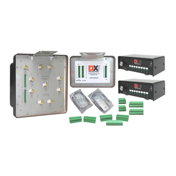
- Page 2 Introduction The 2 x 8 Remote Antenna Smart Two Radio Switch System DXE-RRMX2X8 uses a DXE- RR2X8 remote switch, DXE-MX2X8 interface unit and two DXE-CC-8A control consoles. The two DXE-CC-8A control consoles supply the BCD switching signals to the DXE-MX2X8 interface unit which then sends the appropriate signals to the DXE-RR2X8 remote switch to select one of the eight output ports for each DXE-CC-8A control console.
-
Page 3: Overall Wiring Diagram
Overall Wiring Diagram This diagram shows the overall wiring scheme. Once familiar with this set up, making the actual cables will be easier DXE-CW9S is a shielded control cable that has 10-conductors and works very well for running control signals for the DXE-RR2X8 and DXE-MX2X8. Note: Do not seal the connectors! The connectors are recessed inside a drip edge that prevents water from getting into connectors. - Page 4 MIL and SIL Safety Mode One DXE-CC-8A Control Console is located next to each radio. Each operator can select their desired antenna port using the knob on the DXE-CC-8A. A Green LED on the DXE-CC-8A will light up showing which position is selected. There are two internal jumpers in the DXE-MX2X8 interface unit called MIL and SIL.
- Page 5 Wiring the Connections 1. Connections for the wire are made on the green headers. Loosen each terminal screw until it is near flush with the top of the connector block. 2. Strip approximately 1/4" insulation from the wire end and connect each wire to a terminal by sliding the wire completely into the wire connection hole.
- Page 6 When connecting the short cables from the DXE-RR2X8 to the DXE-MX2X8 ensure the ten-wire cables are wired the same way at both ends to avoid un-necessary troubleshooting. Use the chart below to record which color wire is connected to each terminal connection of each cable. Master Master DXE-RR2X8...
- Page 7 The DXE-MX2X8 is connected to the two DXE-CC-8A control consoles. One is marked as “Radio A” the second is marked as “Radio B”. Two control wire cables are used (one for each DXE-CC- 8A) to avoid having another break-out cable in the radio room. The control signals are BCD logic.
- Page 8 DXE-CW9S is a shielded control cable that has 10-conductors and works very well for running control signals for the DXE-RR2X8 remote switch, DXE-MX2X8 interface unit and the two DXE- CC-8A control consoles.. Note: Do not seal the connectors! The connectors are recessed inside a drip edge that prevents water from getting into connectors.
- Page 9 DXE-RR2X8 and DXE-MX2X8 Installation 1. Secure the DXE-RR2X8B switching unit using the included DXE-SSVC-2P stainless steel V- Saddle Clamp. Mount the DXE-MX2X8 close to the DXE-RR2X8B to keep the interface cable lengths between these units to a minimum using the included DXE-SSVC-2P stainless steel V-Clamp.
- Page 10 Very Simplified Control Logic When selecting the various switch positions, the first control console that selects a particular position has precedence. This means if Radio “A” selects output port #3, them Radio “B” cannot use port #3 at the same time. Radio “B” will not connect to port #3. The operator will know that there is no antenna selected since there will be no audio from any signals coming into Radio “B”.
-
Page 11: Specifications
Every effort is made to supply the latest manual revision with each product. Occasionally a manual will be updated between the time your DX Engineering product is shipped and when you receive it. Please check the DX Engineering web site (www.dxengineering.com) for the latest revision manual. -
Page 12: Technical Support
Warranty All products manufactured by DX Engineering are warranted to be free from defects in material and workmanship for a period of one (1) year from date of shipment. DX Engineering’s sole obligation under these warranties shall be to issue credit, repair or replace any item or part thereof which is proved to be other than as warranted;...
Need help?
Do you have a question about the DXE-RRMX2X8 and is the answer not in the manual?
Questions and answers