Table of Contents
Advertisement
Quick Links
Advertisement
Table of Contents

Related Manuals for Datavideo TPC-700P


Summary of Contents for Datavideo TPC-700P
-
Page 2: Table Of Contents
6.3 H ......26 OW TO ESTORE THE ETWORK ETTINGS EFAULT ALUES CHAPTER 7 THE 8 PRE-SAVED VIRTUAL SCENES FOR THE SE-3200 & TPC- 700/TPC-700P COMBINATION ..............28 7.1 T SE-3200 & TPC-700/TPC-700P NPUT NTERFACE ETTINGS FOR THE ....................29 OMBINATION... - Page 3 SE THE OURCE UNCTION 9.5 PIP ......................50 9.6 S ....................... 51 ETUP CHAPTER 10. INTRODUCTION OF THE BUILT-IN VGB-2000 APP INTERFACE FOR THE TPC-700/TPC-700P ................ 56 10.1 M TPC-700 A & D ........56 NTERFACE OF THE INGLE 10.2 O VGB-2000 A TPC-700/TPC-700P .....
- Page 4 Datavideo Technologies will try to give correct, complete and suitable information. However, Datavideo Technologies cannot exclude that some information in this manual, from time to time, may not be correct or may be incomplete. This manual may contain typing errors, omissions or incorrect information.
-
Page 5: Warnings And Precautions
7. This product should only be operated from the type of power source indicated on the marking label of the AC adapter. If you are not sure of the type of power available, consult your Datavideo dealer or your local power company. -
Page 6: Warranty
When the product exhibits a distinct change in performance, indicating a need for service. Warranty Standard Warranty Datavideo equipment are guaranteed against any manufacturing defects for one year from the date of purchase. The original purchase invoice or other documentary evidence should be ... -
Page 7: Three Year Warranty
Hard Drive, Solid State Drive, SD Card, USB Thumb Drive, Lighting, Camera module, PCIe Card are covered for 1 year. The three-year warranty must be registered on Datavideo's official website or with your local Datavideo office or one of its authorized distributors within 30 days of purchase. -
Page 8: Disposal
Disposal For EU Customers only - WEEE Marking This symbol on the product or on its packaging indicates that this product must not be disposed of with your other household waste. Instead, it is your responsibility to dispose of your waste equipment by handing it over to a designated collection point for the recycling of waste electrical and electronic equipment. -
Page 9: Chapter 1 Introduction
Each button can be customized to your liking. Multi- camera Virtual Studio switching, AUX output, Crosspoint, Flex Source, and PIP assignment can be done by the TPC-700/TPC-700P. Easy to transport to your live production show on the go. Quick connection. -
Page 10: Chapter 2 System Diagram
Chapter 2 System Diagram... -
Page 11: Chapter 3 Connections
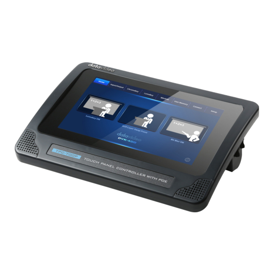
Chapter 3 Connections This chapter will show you the connections of the TPC-700/TPC-700P Touch Panel Controller. For the details of the TPC-700/TPC-700P, please refer to following chapters. 3.1 Front View Interface Description Touch Panel This is the touch panel of the TPC-700/TPC-700P touch... -
Page 12: Rear View
3.2 Rear View Interface Description Rear Panel This is the rear panel of the TPC-700/TPC-700P Touch Panel Controller. It provides standard VESA 10cm x 10cm & 7.5cm x .7.5cm mounting holes. -
Page 13: Left View
RJ-45 Ethernet Interface(for RS-232 Control only) This RJ-45 interface is for RS-232 Control only. If users use the TPC-700/TPC-700P to control the SE-3200, it is no need for this interface to connect due to that the TPC-700/TPC-700P adopts the DVIP protocol to control the SE-3200. -
Page 14: Right View
Interface Description 12VDC IN interface Please connect a 12V DC power cable to this interface for powering the TPC-700/TPC-700P. RJ-45 Ethernet Interface(For DVIP Control & PoE Only) Please connect one end of an RJ-45 Ethernet cable to this interface and then please connect the other end of this cable to the device that must be controlled by the DVIP protocol. -
Page 15: Chapter 4 How To Turn On And Turn Off The Power Of The Tpc-700/Tpc-700P
TPC-700/TPC-700P How to Turn On the Power Please use the ON/OFF power switch which is located on the right side of the TPC-700/TPC-700P to turn on the power of the TPC-700/TPC- 700P. How to Turn Off the Power ... -
Page 16: Chapter 5 Basic Setup
Chapter 5 Basic Setup Before using the TPC-700/TPC-700P to control other devices, please make sure that the basic setup of the TPC-700/TPC-700P is done. This chapter will make the SE-3200 HD 12-Channel Digital Video Switcher as an example for explaining how to set the basic setup between the TPC- 700/TPC-700P and the SE-3200. -
Page 17: Chapter 6 Network Settings
“Network and Software Setup for Switcher” in the SE-3200 user manual to know the IP address, subnet mask and default gateway of the SE-3200. And then please set the IP address of the TPC-700/TPC-700P to be within the same IP range for further operation. - Page 18 Please follow following steps for operation. 1. After opening the TPC-700/TPC-700P interface, please select the “Setup” option. 2. Please press the “Network” button.
- Page 19 3. Please select the “Static” from the “Addr Mode” drop-down menu. 4. Please press the “IP Addr” to enter the IP address which is within the same IP range as the SE-3200. After that, please press the “OK” button.
- Page 20 5. Please press the “Network Mask” and the “Gateway” respectively and then please set those two items to be the same value as the SE-3200.
- Page 21 6. Please press the “Save” button. 7. Please press the “Connect” button.
- Page 22 8. Please press the “Scan” button and then it will scan the IP address of the connected device. 9. Please press the “Connect” button for completing the connection.
-
Page 23: Connect By Dhcp
6.2 Connect by DHCP Please follow following steps for connecting the TPC-700/TPC-700P and the SE- 3200 by the DHCP Mode. 1. Please open the TPC-700/TPC-700P interface and then please press the “Setup” option. 2. Please press the “Network” button. - Page 24 3. Please press the “DHCP” from the drop-down menu and then please press the “Save” button. 4. Please press the “Connect” button.
- Page 25 5. Please press the “Scan” button and then it will scan the IP address of the connected device. 6. Please press the “Connect” button for completing the connection.
-
Page 26: How To Restore The Network Settings Default Values
6.3 How to Restore the Network Settings Default Values Please follow following steps for restoring the TPC-700/TPC-700P network related settings to default values. 1. Please open the TPC-700/TPC-700P App and then please press the “Setup” option. 2. Please press the “Network” button. - Page 27 3. Please press the “Network Def” button. 4. The following dialogue box will appear. Please press the “Yes” button and then the network related settings will be restored to factory default values successfully.
-
Page 28: Chapter 7 The 8 Pre-Saved Virtual Scenes For The Se-3200 & Tpc- 700/Tpc-700P Combination
Datavideo SE-3200 HD 12-Channel Digital Video Switcher allows users to set up to 4-camera EFP Chromakey effect. So, the SE-3200 & TPC- 700/TPC-700P combination allows users to recall the pre-saved 4- camera EFP Chromakey effect virtual scenes easily and rapidly. The default setting for the TPC-700/TPC-700P is that the TPC-700/TPC-700P will recall the No. -
Page 29: The Input Interface Settings For The Se-3200 & Tpc-700/Tpc-700P Combination
7.1 The Input Interface Settings for the SE-3200 & TPC- 700/TPC-700P Combination Before recalling the No. 101 to No. 108 user memories’ virtual scenes, users need to know the corresponding relationship between each interface of the SE-3200 rear panel and the elements for each pre- saved virtual scene. - Page 30 SDI IN 2 Please set the Camera 2 in the middle to shoot the close- up for the talent and guests who are sitting in front of the (CH2) green mat. SDI IN 3 The Camera 3 must be set on the right side to shoot the ...
- Page 31 SDI IN 4 The Camera 4 must be set on the left side to shoot the close-up for the guests who are sitting in front of the (CH4) green mat. The built-in virtual scene from the SE-3200(Wide Angle virtual scene) The built-in virtual scene from the SE-3200(The close-up picture is located in the middle)
-
Page 32: The 8 Pre Saved Virtual Scenes For The Se-3200 And Tpc-700/Tpc-700P Combination
Please connect a PC to the HDMI IN9 interface of the SE- 3200(CH9)(for playing slides or videos) 7.2 The 8 Pre-saved virtual scenes for the SE-3200 and TPC- 700/TPC-700P Combination User Combination of Final Composite Screen Screen Elements Wide Angle with... - Page 33 Talent A Close-up Half-Body Talent A Chromakey with Virtual with Background Scene (CH3 Chromakey+CH7 Virtual Scene) Talent B Close-up Talent B Chromakey with Virtual Scene with Background (CH4 Chromakey +CH8 Virtual Scene) Talent A+PC Source Talent A Half-Body + Content (CH3 Chromakey+CH9 Background)...
- Page 34 Talent B+ PC Source Talent B Half-Body +Content (CH4 Chromakey+CH9 Background) Talent A Close-up Talent A Half-Body Chromakey with Virtual with Background+ PC Scene+ Content Source)(CH3 Chromakey +CH7 Background+CH9 PIP) Talent B Close-up Talent B Half-Body Chromakey with Virtual with Background +PC Scene+ Content Source(CH4 Chromakey+CH8...
-
Page 35: Chapter 8. How To Set The Chromakey, Save A Still To Memory, P-In-P And Still Functions
It is necessary to use the Chromakey and Still related functions of the SE-3200 for controlling the SE-3200 and for recalling the pre-saved virtual scenes directly by the TPC-700/TPC-700P. For the setting details and the operating steps, please refer to the 4.2 Keyer, 4.3 Chroma, 4.4 P-In-P and the Still related paragraphs of the 4.9 Files from the SE-... -
Page 36: Chapter 9 Introduction Of The Se-3200 App Interface For The Tpc-700/Tpc-700P
“Virtual Studio”, “AUX”, “Cross Point”, “Flex Source”, “PIP” and “Setup” options for users to control the SE-3200 remotely by the TPC-700/TPC-700P and an RJ-45 Ethernet cable. The main interface of the built-in SE-3200 control App for the TPC-700/TPC-700P is shown as following diagram. -
Page 37: Virtual Scenes
9.1 Virtual Scenes The Virtual Studio option allows users to recall the pre-saved No. 101 to No. 108 User Mems settings in the SE-3200 by the TPC-700/TPC- 700P. There are 8 virtual scenes can be used by users including “Wide Angle with background”, “Close-up with background”, “Talent A close- up with background”, “Talent B close-up with background”, “Talent A + PC Source”, “Talent B + PC Source”, “Talent A close-up with... - Page 38 2. Close-up with background 3. Talent A close-up with background...
- Page 39 4. Talent B close-up with background 5. Talent A + PC Source...
- Page 40 6. Talent B + PC Source 7. Talent A close-up with background + PC Source.
-
Page 41: How To Recall The Pre-Saved Virtual Scenes By The Tpc-700/Tpc- 700P
1. Please make sure that all of the 8 virtual scenes are saved into the No. 101 to No.108 User Mems in advance. Moreover, please make sure that the SE- 3200 main unit, the control panel, the TPC-700/TPC-700P and the router are connected correctly. -
Page 42: Aux
9.2 AUX The Datavideo TPC-700/TPC-700P with the SE-3200 control software allows users to use the “AUX” function. The “AUX” function allows users to assign signal sources including CH1 to CH-12 input sources, PGM, PVW, CLN PGM, CLN PVW, PG + DSK, MULTIV, MULTIV2, STILL1, STILL2, FLEX SRC and FLEX SRC2 randomly to the output interfaces such as SDI1, SDI2, SDI3, SDI4, SDI5, SDI5, SDI6, HDMI1, HDMI2 and HDMI3 to be the output sources. - Page 43 2. Please select your desired signal source for output from the “SELECT” area. 3. Users can finish the signal assigning for the AUX function.
-
Page 44: Cross Point
9.3 Cross Point The “Cross Point” option allows users to adjust the sequence of the input signals by themselves without changing any input cables. For example, users can assign the signal source which is originally connected to input 2 to be the signal source of input 1. - Page 45 Note:If you want to turn off the output of the “VIDEO XPT” area, please tap the “OFF” button. If you want to use the embedded audio of the output video as the output audio source, please tap the “Follow” button. ...
- Page 46 2. Users can enter the “PGM AUDIO SETTING” interface to adjust the audio Gain and audio Delay. How to Use the “PGM AUDIO SETTING” Interface 1. Please tap the No.1 arrow to decrease the Audio Gain and Audio Delay. 2.
-
Page 47: Flex Source
3. Please tap the No. 3 slider to increase or decrease the Audio Gain and Audio Delay by dragging the No.3 slider forward or backward. 4. Please tap the No. 4 “OK” button to make the setting effective and to go back to the previous screen. -
Page 48: How To Use The Flex Source Function
9.4.1 How to Use the Flex Source Function Please follow following steps for using the Flex Source function. How to Set the Background Picture for the Flex Source 1. At first, please tap the “Src Bgnd” button which is located at the “FLEX 1” area to select the background function for the Flex Source. - Page 49 5. Please tap the left or the right arrow button to adjust the scale of the “X”, “Y” or “SIZE”. Note: When the X, Y or Size character become orange, users can tap that character once again and then the character will become light blue. When the character becomes light blue, users are forbidden to adjust the scale of X, Y or SIZE.
-
Page 50: Pip
Note: If users do not want to show the same PIP screens on both FLEX 1 and FLEX 2, please remember to use the ON/OFF button to hide the repetitive PIP screens. 9.5 PIP The main interface of the PIP option allows users to set the PIP related functions. -
Page 51: Setup
X, Y or SIZE. 9.6 Setup The built-in SE-3200 control interface of the TPC-700/TPC-700P allows users to set many parameters including Language, Network, Connect, FW Version, Model and Screen Saver. The main interface for the Setup is shown as following diagram. - Page 52 After that, users can select their desired language. If the “Save” button is pressed, it will go back to previous page after the setting is saved. If the “Cancel” button is pressed, it will go back to previous page directly. 2.
- Page 53 1. Addr Mode:Please select Static IP Mode or DHCP Mode from this drop- down menu. 2. IP Address, Network Mask, Gateway, Primary DNS and Secondary DNS. Once the IP Addr, Network Mask, Gateway, Primary DNS or Secondary DNS is pressed, the keyboard which is shown as following diagram will be shown for users to enter related values.
- Page 54 Please press the “Scan” button and then it will scan current IP address. Press the “Connect” button for connecting the TPC-700/TPC-700P to the SE-3200. Press the “Disconnect” button for canceling the connection. 4. FW Version:This will show current software version.
- Page 55 If the “Screen Saver” is “OFF”: The screen saver will be closed for easy operation. 7. Quit App: Press this button can exit current App and go back to the main screen of the TPC-700/TPC-700P. 8. Shut Down: Press this button can shut down the TPC-700/TPC-700P.
-
Page 56: Chapter 10. Introduction Of The Built-In Vgb-2000 App Interface For The Tpc-700/Tpc-700P
Chapter 10. Introduction of the Built-in VGB-2000 App Interface for the TPC-700/TPC-700P When the User Memory of the SE-1200MU is set, users can use the TPC-700 Touch Panel Controller to apply their needed default mode directly. 10.1 Main Interface of the TPC-700 App-Single & Dual Please see following diagram for the Single &... -
Page 57: Operation Steps For The Vgb-2000 App For Tpc-700/Tpc-700P
10.2 Operation Steps for the VGB-2000 App for TPC- 700/TPC-700P The Datavideo TPC-700 Touch Panel Controller allows users to tap the option which is shown on the screen for applying the pre-saved effects that are set by the SE-1200MU. This allows users to use more simple way for applying their desired effects when shooting the teaching videos. - Page 58 Close Up + Interactive Pen Mark + Logo Interactive Pen Mark + Logo...
- Page 59 Interactive Pen Mark Close Up with Chromakey + Slides...
- Page 60 Dual Camera Effects Close Up + Interactive Pen Mark Close Up + Interactive Pen Mark + Logo...
- Page 61 Interactive Pen Mark + Logo Interactive Pen Mark...
- Page 62 Close Up with Chromakey Wide Angle with Chromakey...
- Page 63 Wide Angle with Chromakey + Interactive Pen Mark...
-
Page 64: Setting Option Of The Vgb-2000 App For The Tpc-700/Tpc-700P
10.3 Setting Option of the VGB-2000 App for the TPC- 700/TPC-700P For the “Setting” option of the VGB-2000 App, please see following section. 1. Please click the “Setting” option of the VGB-2000 App and then you can enter the “Setting” interface which includes “Language”, “Quit APP”, “Shut... - Page 65 Languages After clicking the “Language” option, it can show three languages including “English”, “Traditional Chinese” and “Simplified Chinese” for you to select. After the selection is finished, please click the “Save” button to save the settings. Quit APP After clicking the “Quit App”...
-
Page 66: Chapter 11. Software Update
3. There is a folder with the latest software update files which the folder name is “datavideo” after the software is unzipped. 4. Please copy the whole “datavideo” folder to the root directory of your USB thumb drive. 5. Please insert your USB thumb drive with the latest TPC-700/TPC-700P software into the USB port which is located at the left side of the TPC- 700/TPC-700P. - Page 67 Note: After the software update is finished, there is a file which the file name is “done” will be generated automatically by the TPC-700/TPC-700P system and will be saved in your USB thumb drive. If users want to update the same version of the software for the next time, please remember to delete that “done”...
-
Page 68: Chapter 12. Settings
Chapter 12. Settings After the TPC-700/TPC-700P is turned on, it will enter the main screen and there is a “Settings” option which is located at the top-right side of the main screen. Settings After clicking the “Settings” button, you can enter the “Settings” interface. In the “Settings”... - Page 69 2. Please unzip the downloaded file TPC-700_product model name_v x.x.x in your PC or laptop. 3. After the file is unzipped, there is a “datavideo” file folder with a file which the name is “TPC700.apkg” in it. 4. Please prepare a USB flash drive and then save the unzipped “datavideo” file folder with the “TPC700.apkg”...
- Page 70 For the TPC-700P, please unplug and replug the RJ-45 Ethernet cable which is connected to the RJ-45 Ethernet interface of the TPC-700P. 6. After the rebooting or unplugging and replugging is finished, the device will enter its initial screen. Please click “Settings”.
- Page 71 Uninstall APP: The “Uninstall APP” option allows you to uninstall the APP for the product which is needed to be removed. Please see following steps for knowing how to uninstall APP by the “Uninstall APP” option. 1. At first, please click the “Uninstall APP” button. 2.
-
Page 72: Chapter 13. Dimensions
Chapter 13. Dimensions Unit: mm... -
Page 73: Chapter 14. Specifications
7” capacitive touch screen Touch Screen 800 x 480 Resolution Software Upgrade via USB 2.0 interface Control Protocol via RS-232(RJ-45 interface) Power DC 12V 802.3af(For TPC-700P Only) Power Consumption 220 x 152 x 79 (mm) Dimension Weight 0.85Kg Operating Temp. 0~40 °C... - Page 74 Note...
- Page 75 Note...
-
Page 76: Service And Support
Datavideo Technologies Co., Ltd. All rights reserved 2020 May.-26.2021 Ver:E4...
Need help?
Do you have a question about the TPC-700P and is the answer not in the manual?
Questions and answers