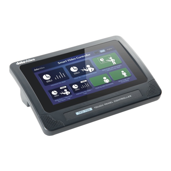
Datavideo TPC-700 Instruction Manual
Touch panel controller & touch panel controller with poe
Hide thumbs
Also See for TPC-700:
- Instruction manual (56 pages) ,
- Instruction manual (76 pages) ,
- Instruction manual (156 pages)
Table of Contents
Advertisement
Quick Links
Advertisement
Table of Contents

Related Manuals for Datavideo TPC-700


Summary of Contents for Datavideo TPC-700
-
Page 2: Table Of Contents
....................14 IGHT CHAPTER 4 HOW TO TURN ON AND TURN OFF THE POWER OF THE TPC- 700/TPC-700P....................15 CHAPTER 5 TPC-700 & TPC-700P’S SETTINGS OPTION ......... 16 CHAPTER 6 BASIC SETUP ................23 6.1 C IP A ..............23... - Page 3 NTERFACE OF THE INGLE 11.2 O VGB-2000 A TPC-700/TPC-700P ..... 62 PERATION TEPS FOR THE PP FOR CHAPTER 12 INTERFACE INTRODUCTION OF THE TPC-700/TPC-700P BUILT-IN DVK-400 APP ....................69 12.1 H ..................... 69 12.2 I ..................71 NPUT UTPUT 12.3 C ....................
- Page 4 Datavideo Technologies will try to give correct, complete and suitable information. However, Datavideo Technologies cannot exclude that some information in this manual, from time to time, may not be correct or may be incomplete. This manual may contain typing errors, omissions or incorrect information.
-
Page 5: Warnings And Precautions
7. This product should only be operated from the type of power source indicated on the marking label of the AC adapter. If you are not sure of the type of power available, consult your Datavideo dealer or your local power company. -
Page 6: Warranty
Warranty Standard Warranty Datavideo equipment are guaranteed against any manufacturing defects for one year from the date of purchase. The original purchase invoice or other documentary evidence should be supplied at the time of any request for repair under warranty. -
Page 7: Three Year Warranty
Hard Drive, Solid State Drive, SD Card, USB Thumb Drive, Lighting, Camera module, PCIe Card are covered for 1 year. The three-year warranty must be registered on Datavideo's official website or with your local Datavideo office or one of its authorized distributors within 30 days of purchase. -
Page 8: Disposal
Disposal For EU Customers only - WEEE Marking This symbol on the product or on its packaging indicates that this product must not be disposed of with your other household waste. Instead, it is your responsibility to dispose of your waste equipment by handing it over to a designated collection point for the recycling of waste electrical and electronic equipment. -
Page 9: Chapter 1 Introduction
Each button can be customized to your liking. Multi- camera Virtual Studio switching, AUX output, Crosspoint, Flex Source, and PIP assignment can be done by the TPC-700/TPC-700P. Easy to transport to your live production show on the go. Quick connection. -
Page 10: Chapter 2 System Diagram
Chapter 2 System Diagram... -
Page 11: Chapter 3 Connections
Chapter 3 Connections This chapter will show you the connections of the TPC-700/TPC-700P Touch Panel Controller. For the details of the TPC-700/TPC-700P, please refer to following chapters. 3.1 Front View Interface Description Touch Panel This is the touch panel of the TPC-700/TPC-700P touch... -
Page 12: Rear View
3.2 Rear View Interface Description Rear Panel This is the rear panel of the TPC-700/TPC-700P Touch Panel Controller. It provides standard VESA 10cm x 10cm & 7.5cm x .7.5cm mounting holes. -
Page 13: Left View
RJ-45 Ethernet Interface(for RS-232 Control only) This RJ-45 interface is for RS-232 Control only. If users use the TPC-700/TPC-700P to control the SE-3200, it is no need for this interface to connect due to that the TPC-700/TPC-700P adopts the DVIP protocol to control the SE-3200. -
Page 14: Right View
Interface Description 12VDC IN interface Please connect a 12V DC power cable to this interface for powering the TPC-700/TPC-700P. RJ-45 Ethernet Interface(For DVIP Control & PoE Only) Please connect one end of an RJ-45 Ethernet cable to this interface and then please connect the other end of this cable to the device that must be controlled by the DVIP protocol. -
Page 15: Chapter 4 How To Turn On And Turn Off The Power Of The Tpc-700/Tpc-700P
TPC-700/TPC-700P to turn off the power of the TPC-700/TPC-700P Use the APP: There is a Power-Off button which is located at the bottom side of the TPC-700 APP. Press this button can turn off the power of the TPC-700/TPC-700P. -
Page 16: Chapter 5 Tpc-700 & Tpc-700P's Settings Option
Chapter 5 TPC-700 & TPC-700P’s Settings Option After you turn on the TPC-700 or the TPC-700P, it will enter the main screen and there is a “Settings” icon which is located at the top-right side of the main screen. After pressing the icon, you can enter the “TPC-700 Setup” interface, the purpose for this “TPC-700 Setup”... - Page 17 Chinese. After that, please press the “Save” button for saving the settings. TPC-700 Network: Please press this key to set various network related parameters including DHCP ON/OFF switch, IP address, Network Mask, Gateway and Primary DNS. The main interface of the “TPC-700 Network”...
- Page 18 IP address manually from this section. After the static IP address is entered, please tap the “OK” button for applying Note: Please pay attention that the static IP address of the TPC-700/TPC- 700P must be within the same LAN according to the default static IP...
- Page 19 Network Mask: Please press this button for setting the Network Mask manually. The default Network Mask is 255.255.255.0 Gateway: Please press this button for setting the Gateway address manually. Please refer to user manuals of different product models for setting this value in consistent with the default value of each product.
- Page 20 MAC Address: This section will show the MAC Address of the TPC- 700/TPC-700P. APP Manage: Press this button allows you to install related Apps for the Datavideo products in the TPC-700/TPC-700P. The main interface of the “App Manage” option is shown in the following diagram. ...
- Page 21 Autorun last App ON/OFF toggle switch: If this toggle switch is “ON”, for the next time when the TPC-700 or the TPC-700P is turned on, it will run the app which is operated for the last time automatically.
- Page 22 FW Version: This section will show current version number of the “App Manage” software which is installed in the TPC-700 or the TPC-700P. LCD Backlight: This slider allows you to adjust the LCD Backlight brightness with the range of 20%-100%.
-
Page 23: Chapter 6 Basic Setup
Chapter 6 Basic Setup Before using the TPC-700/TPC-700P to control other devices, please make sure that the basic setup of the TPC-700/TPC-700P is done. This chapter will make the SE-3200 HD 12-Channel Digital Video Switcher as an example for explaining how to set the basic setup between the TPC- 700/TPC-700P and the SE-3200. -
Page 24: Chapter 7 Network Settings
“Network and Software Setup for Switcher” in the SE-3200 user manual to know the IP address, subnet mask and default gateway of the SE-3200. And then please set the IP address of the TPC-700/TPC-700P to be within the same IP range for further operation. - Page 25 Please follow following steps for operation. 1. After the TPC-700 or the TPC-700P is turned on, please tap the “Settings” icon. 2. Please press the “TPC-700 Network” option.
- Page 26 Note: If SE-3200’s IP address is not the default IP address, you need to click the “IP Address” button for setting the SE-3200 and TPC-700/TPC-700P’s IP addresses within the same LAN by using the keypad which is shown in the...
- Page 27 4. After going back to the “TPC-700 Network” screen, please press the “Apply” button which is located at the top-right side for applying the settings. 5. After going back to the main interface of the TPC-700/TPC-700P, please tap the SE-3200 App.
- Page 28 6. After entering the SE-3200 App, please click the “Setup” and then click the “Connect”button. 7. Please press the “Scan” button to find the connected SE-3200. After that, please select the correct SE-3200 IP address from the drop-down menu and then please press the “Connect” button for connecting the SE-3200 by the TPC-700/TPC-700P.
-
Page 29: Connect By Dhcp
7.2 Connect by DHCP Please follow following steps for connecting the TPC-700/TPC-700P and the SE- 3200 by the DHCP Mode. 1. After the TPC-700 or the TPC-700P is turned on, please tap the “ Settings” icon. 2. Please tap the “TPC-700 Network” option. - Page 30 3. Please turn “ON” the “DHCP ON/OFF” toggle switch. After that, the TPC-700 or the TPC-700P will obtain the network related parameters including IP address, Network Mask, Gateway AND Primary DNS from the connected router automatically. After all parameters are obtained, please press the “Apply”...
- Page 31 “Connect” button. 6. Please click the “Scan” button to find the connected SE-3200. Please select the IP address of the connected SE-3200 from the drop-down menu and then tap the “Connect” button to connect the TPC-700/TPC-700P to the SE-3200.
-
Page 32: Chapter 8 The 8 Pre-Saved Virtual Scenes For The Se-3200 & Tpc- 700/Tpc-700P Combination
700/TPC-700P combination allows users to recall the pre-saved 4- camera EFP Chromakey effect virtual scenes easily and rapidly. The default setting for the TPC-700/TPC-700P is that the TPC-700/TPC-700P will recall the No. 101~No. 108 virtual scenes that are pre-saved in the SE-3200. -
Page 33: The Input Interface Settings For The Se-3200 & Tpc-700/Tpc-700P Combination
8.1 The Input Interface Settings for the SE-3200 & TPC- 700/TPC-700P Combination Before recalling the No. 101 to No. 108 user memories’ virtual scenes, users need to know the corresponding relationship between each interface of the SE-3200 rear panel and the elements for each pre- saved virtual scene. - Page 34 SDI IN 2 Please set the Camera 2 in the middle to shoot the close- (CH2) up for the talent and guests who are sitting in front of the green mat. SDI IN 3 The Camera 3 must be set on the right side to shoot the (CH3)...
- Page 35 SDI IN 4 The Camera 4 must be set on the left side to shoot the (CH4) close-up for the guests who are sitting in front of the green mat. The built-in virtual scene from the SE-3200(Wide Angle virtual scene) The built-in virtual scene from the SE-3200(The close-up picture is located in the middle)
-
Page 36: The 8 Pre Saved Virtual Scenes For The Se-3200 And Tpc-700/Tpc-700P Combination
Please connect a PC to the HDMI IN9 interface of the SE- 3200(CH9)(for playing slides or videos) 8.2 The 8 Pre-saved virtual scenes for the SE-3200 and TPC- 700/TPC-700P Combination User Combination of Final Composite Screen Screen Elements Wide Angle with Full-Body Chromakey with Virtual Scene Background (CH1 Chromakey+CH5... - Page 37 Talent A Close-up Half-Body Talent A Chromakey with Virtual with Background Scene (CH3 Chromakey+CH7 Virtual Scene) Talent B Close-up Talent B Chromakey with Virtual Scene with Background (CH4 Chromakey +CH8 Virtual Scene) Talent A+PC Source Talent A Half-Body + Content (CH3 Chromakey+CH9 Background)...
- Page 38 Talent B+ PC Source Talent B Half-Body +Content (CH4 Chromakey+CH9 Background) Talent A Close-up Talent A Half-Body Chromakey with Virtual with Background+ PC Scene+ Content Source)(CH3 Chromakey +CH7 Background+CH9 PIP) Talent B Close-up Talent B Half-Body Chromakey with Virtual with Background +PC Scene+ Content Source(CH4 Chromakey+CH8...
-
Page 39: Chapter 9. How To Set The Chromakey, Save A Still To Memory, P-In-P And Still Functions
It is necessary to use the Chromakey and Still related functions of the SE-3200 for controlling the SE-3200 and for recalling the pre-saved virtual scenes directly by the TPC-700/TPC-700P. For the setting details and the operating steps, please refer to the 4.2 Keyer, 4.3 Chroma, 4.4 P-In-P and the Still related paragraphs of the 4.9 Files from the SE-... -
Page 40: Chapter 10 Introduction Of The Se-3200 App Interface For The Tpc-700/Tpc-700P
“Virtual Studio”, “AUX”, “Cross Point”, “Flex Source”, “PIP” and “Setup” options for users to control the SE-3200 remotely by the TPC-700/TPC-700P and an RJ-45 Ethernet cable. The main interface of the built-in SE-3200 control App for the TPC-700/TPC-700P is shown as following diagram. -
Page 41: Virtual Scenes
10.1 Virtual Scenes The Virtual Studio option allows users to recall the pre-saved No. 101 to No. 108 User Mems settings in the SE-3200 by the TPC-700/TPC- 700P. There are 8 virtual scenes can be used by users including “Wide Angle with background”, “Close-up with background”, “Talent A close-... - Page 42 2. Close-up with background 3. Talent A close-up with background...
- Page 43 4. Talent B close-up with background 5. Talent A + PC Source...
- Page 44 6. Talent B + PC Source 7. Talent A close-up with background + PC Source.
-
Page 45: How To Recall The Pre - Saved Virtual Scenes By The Tpc-700/Tpc-700P
1. Please make sure that all of the 8 virtual scenes are saved into the No. 101 to No.108 User Mems in advance. Moreover, please make sure that the SE- 3200 main unit, the control panel, the TPC-700/TPC-700P and the router are connected correctly. -
Page 46: Aux
10.2 AUX The Datavideo TPC-700/TPC-700P with the SE-3200 control software allows users to use the “AUX” function. The “AUX” function allows users to assign signal sources including CH1 to CH-12 input sources, PGM, PVW, CLN PGM, CLN PVW, PG + DSK, MULTIV, MULTIV2, STILL1, STILL2, FLEX SRC and FLEX SRC2 randomly to the output interfaces such as SDI1, SDI2, SDI3, SDI4, SDI5, SDI5, SDI6, HDMI1, HDMI2 and HDMI3 to be the output sources. - Page 47 2. Please select your desired signal source for output from the “SELECT” area. 3. Users can finish the signal assigning for the AUX function.
-
Page 48: Cross Point
10.3 Cross Point The “Cross Point” option allows users to adjust the sequence of the input signals by themselves without changing any input cables. For example, users can assign the signal source which is originally connected to input 2 to be the signal source of input 1. - Page 49 Note:If you want to turn off the output of the “VIDEO XPT” area, please tap the “OFF” button. If you want to use the embedded audio of the output video as the output audio source, please tap the “Follow” button. ...
- Page 50 2. Users can enter the “PGM AUDIO SETTING” interface to adjust the audio Gain and audio Delay. How to Use the “PGM AUDIO SETTING” Interface...
-
Page 51: Flex Source
1. Please tap the No.1 arrow to decrease the Audio Gain and Audio Delay. 2. Please tap the No. 2 arrow to increase the Audio Gain and Audio Delay. 3. Please tap the No. 3 slider to increase or decrease the Audio Gain and Audio Delay by dragging the No.3 slider forward or backward. -
Page 52: How To Use The Flex Source Function
10.4.1 How to Use the Flex Source Function Please follow following steps for using the Flex Source function. How to Set the Background Picture for the Flex Source 1. At first, please tap the “Src Bgnd” button which is located at the “FLEX 1” area to select the background function for the Flex Source. - Page 53 2. Please tap the source signal channel that you want to use to be the Src background picture from the “SELECT” area. (The source signal channels include BLK, 1~12, STILL 1 & STILL 2, MATTE and BARS). How to Set the Sub-Picture Source Signal for the P-In-P of Flex Source 1.
-
Page 54: Pip
Flex 1 : Flex 2 : Bgnd x 1, PIP x 3 Different Bgnd x 1, PIP x 1 Flex 1 : Flex 2 : Bgnd x 1, PIP x 4 Different Bgnd x 1, PIP x 0 Users can know from the above-mentioned examples that the FLEX 1 mode and the FLEX 2 mode can display different Bgnd background screen respectively. - Page 55 How to Set the Sub-Picture Source Signal for the PIP 1. At first, please tap the “Src 1”, “Src 2”, “Src 3” or “Src 4” button from the PIP area. 2. Please tap the source signal channel that you want to use to be the Src 1, Src 2, Src 3 or Src 4 sub-signal from the “SOURCE”...
-
Page 56: Setup
10.6 Setup The built-in SE-3200 control interface of the TPC-700/TPC-700P allows users to set many parameters including Language, Network, Connect, FW Version, Model and Screen Saver. The main interface for the Setup is shown as the following diagram. 1. Language: This button allows users to select three different language interfaces including Traditional Chinese, English and Simplified Chinese. - Page 57 After that, please click the “Connect” button to connect the TPC- 700/TPC-700P and the SE-3200. If the “Disconnect” button is pressed during the TPC-700/TPC-700P and the SE-3200 are connected, the connection will be cancelled. If the “Cancel” button is pressed, it will go...
- Page 58 3. Screen Saver: Please press this button to enter the “Screen Saver” main interface which allows you to adjust the screen saver wait time within 0(OFF) to 10 minutes range by using a slider. After the adjustment is finished, please click the “Save”...
- Page 59 5. Model: This column will show the product model which is connected by this App, which is the SE-3200. 6. Quit App: Please press this button to quit the SE-3200 App and then go back to the main screen of the TPC-700/TPC-700P.
-
Page 60: Chapter 11. Introduction Of The Built-In Vgb-2000 App Interface For The Tpc-700/Tpc-700P
Chapter 11. Introduction of the Built-in VGB-2000 App Interface for the TPC-700/TPC-700P When the User Memory of the SE-1200MU is set, users can use the TPC-700 Touch Panel Controller to apply their needed default mode directly. 11.1 Main Interface of the TPC-700 App-Single & Dual Please see following diagram for the Single &... - Page 61 Chromakey” and “Wide Angle with Chromakey + Interactive Pen Mark”. Moreover, you can choose Traditional Chinese, Simplified Chinese or English from the language drop-down menu . Click the button allows you to quit the VGB-2000 App and then go back to the main interface of the TPC-700/TPC-700P.
-
Page 62: Operation Steps For The Vgb-2000 App For Tpc-700/Tpc-700P
RS-232 interface which is on the rear panel of the VGB-2000 to the RJ-45 interface of the TPC-700. Step 2. After the preset settings of the SE-1200MU are set, users can apply their desired effects by tapping the option which is shown on the TPC-700 screen directly. ... - Page 63 Close Up + Interactive Pen Mark + Logo Interactive Pen Mark + Logo...
- Page 64 Interactive Pen Mark Close Up with Chromakey + Slides...
- Page 65 Dual Camera Effects Close Up + Interactive Pen Mark Close Up + Interactive Pen Mark + Logo...
- Page 66 Interactive Pen Mark + Logo Interactive Pen Mark...
- Page 67 Close Up with Chromakey Wide Angle with Chromakey...
- Page 68 Wide Angle with Chromakey + Interactive Pen Mark...
-
Page 69: Chapter 12 Interface Introduction Of The Tpc-700/Tpc-700P Built-In Dvk-400 App
“Input/Output”, Chromakey”, “Lumakey” “Window”, “User Memory”, “Connect” and “Setup” options for users to control the DVK-400 remotely by using the TPC-700/TPC-700P and the RJ-45 Ethernet cable connection. The main interface of the TPC-700/TPC-700P built-in DVK-400 app is shown in the following diagram. 12.1 Home After related parameters in the DVK-400 PC App are set in advance, the “Home”... - Page 70 Lumakey ON/OFF: Press this button allows you to switch between the “Lumakey ON”and “Lumakey OFF”. Lumakey ON: This allows you to apply the Lumakey effect. Lumakey OFF: If this button is pressed, the Lumakey effect will not be applied.
-
Page 71: Input/Output
If the “BG Blur ON” is set, it will turn on the BG Blur function. If the “BG Blur OFF” is set, it will turn off the BG Blur function. 12.2 Input/Output After related parameters in the DVK-400 PC App are set in advance, the Input/Output option allows you to select the foreground input source and the output or preview screen type. -
Page 72: Chromakey
The output image sources are shown in the following diagram. FG: The input source of the foreground camera. BG: The input source of the background camera. Matte: Mask. PFG: Processed Foreground Image. Comp: Composite image for foreground and background images ... -
Page 73: Lumakey
Chromakey ON/OFF:Click this toggle switch to turn on or turn off the Chromakey function. Black Level: The Black Level value can be adjusted directly by using this slider. The default value of the Black Level is 200. If this value is increased, black objects or hair will be more obvious. - Page 74 Lumakey ON/OFF toggle switch:Click this toggle switch to turn on or turn off the Lumakey function. KEY MODE: There are two Modes including Black and White Modes. Click this button once to switch between the Black and White. Select “Black”...
-
Page 75: Window
12.5 Window After related parameters in the DVK-400 PC App are set in advance, the Window option allows you to turn on or turn off the “Garbage Window” and “Holdout Window” ON/OFF buttons. Moreover, it also allows you to adjust the “Top”, “Bottom”, ”Left”... -
Page 76: User Memory
12.6 USER MEMORY After related parameters in the DVK-400 PC App are set in advance, the User Memory option allows you to save or load up to 8 setting values. How to save the User Memory setting: At first, please make sure that your desired settings are set in the DVK-400 PC App in advance. -
Page 77: Connect
DVK-400 which is connected by the TPC- 700/TPC-700P automatically. Select Device:This option will show the IP address of the connected DVK-400. Connect:When the interface is selected and the DVK-400 is found, please click this “Connect” button to connect the TPC-700/TPC-700P with the DVK- 400. -
Page 78: Setup
12.8 Setup After related parameters in the DVK-400 PC App are set in advance, the “Setup” option allows you to set various parameters including “Output Resolution”, “HDMI Output Format”, “Language”, “FW Version”, “FPGA Version”, “Bootloader Version” and “Screen Saver”. The main interface of the “Setup”... - Page 79 Output Resolution:Please press this button to select your desired output resolution. After that, please press the “Save” button to select your desired DVK-400 output resolution. HDMI Output Format:Please press this button to select your desired HDMI output format from the three output formats which are shown in the following diagram.
- Page 80 Bootloader Version:This column will show the Bootloader Version. Note:The FW Version, FPGA Version and Bootloader Version will be shown only when the TPC-700 or the TPC-700P is connected to the DVK-400 successfully. Factory Default:After the “Factory Default” button is pressed, the Factory Default confirmation dialogue box will be shown.
- Page 82 Quit APP:After the “Quit APP” button is pressed, the “Quit APP” dialogue box will be shown. After the “OK” button is pressed, the DVK- 400 App will be closed.
- Page 83 Screen Saver: After entering the “Setup” page, please press the “right arrow” button to show the “Screen Saver” option which is shown in the following diagram. After pressing the “Screen Saver” button, you can see the “Screen Saver” adjustment slider for you to adjust the “Screen Saver” wait time from 0(OFF) to 10 minutes which is shown in the following diagram.
-
Page 84: Chapter 13. Software Update (App Manage Sw)
3. There is a folder with the latest software update files which the folder name is “datavideo” after the software is unzipped. 4. Please copy the whole “datavideo” folder to the root directory of your USB thumb drive. 5. Please insert your USB thumb drive with the latest TPC-700/TPC-700P software into the USB port which is located at the left side of the TPC- 700/TPC-700P. - Page 85 Note: After the software update is finished, there is a file which the file name is “done” will be generated automatically by the TPC-700/TPC-700P system and will be saved in your USB thumb drive. If users want to update the same version of the software for the next time, please remember to delete that “done”...
-
Page 86: Chapter 14. Dimensions
Chapter 14. Dimensions Unit: mm... -
Page 87: Chapter 15. Specifications
Chapter 15. Specifications TPC-700/TPC-700P Specifications Touch Screen 7” capacitive touch screen Touch Screen 800 x 480 Resolution Software Upgrade via USB 2.0 interface Control Protocol via RS-232(RJ-45 interface) Power DC 12V 802.3af(For TPC-700P Only) Power Consumption 220 x 152 x 79 (mm) -
Page 88: Introduction
1. For the TPC-700/TPC-700P App Manage Software, there is one zip file with the file name: tpc700_v2.0.15_20210714.zip 2. For the TPC-700/TPC-700P App for each product model, there is one zip file with the file name (take SE-3200 as an example): datavideo_se3200_v2.2.10.7zip... -
Page 89: Software Update Preparation
2.2 Software Update Preparation The following items are required to perform this Software update. Please prepare these items in advance before performing the update. The TPC-700 or the TPC-700P is TPC-700 or TPC-700Px 1 needed for updating the Software. USB 2.0 or USB 3.0 USB Flash Drive x... -
Page 90: System Connection Diagram
2.3 System Connection Diagram TPC-700 Power Flash Drive... - Page 91 TPC-700P Powered by an Ethernet Cable or a 12V DC IN Cable Flash Drive Note: Only the TPC-700P supports the “PoE” function. If the power is supplied by the Ethernet cable, please DO NOT use the DC IN power cable as the power source.
-
Page 92: Checking The Software Version
The Software version for the “App Manage” software. 2.4.1. Please connect a DC 12V power adapter. Please connect a DC 12V power adapter to the TPC-700 or the TPC-700P. 2.4.2 Please turn on the power. Please turn on the power of the TPC-700 or the TPC-700P. - Page 93 The current version for the App for different product models. 2.4.5. Please connect a DC 12V power adapter. Please connect a DC 12V power adapter to the TPC-700 or the TPC-700P. 2.4.6 Please turn on the power. Please turn on the power of the TPC-700 or the TPC-700P.
- Page 94 2.4.8 If the TPC-700 or the TPC-700P is not connected to the assigned product model, the following two dialogue boxes will be shown. If the TPC-700 or the TPC-700P is not connected to the assigned product model, the following two dialogue boxes will be shown. Please tap the “Setup”...
- Page 95 2.4.9 You can see the current app version of the selected model. The current app version of the selected model will be shown in the following diagram.
-
Page 96: Preparing The Software
The file name for the TPC-700/TPC-700P App for the specific product model (take SE-3200 as an example) is “datavideo_se3200_v2.2.10.zip” Please unzip the downloaded Software files into the hard disk of your laptop and then you can see the following file folders for the TPC-700 or the TPC- 700P. ... - Page 97 Please insert the USB flash drive to the USB interface of the TPC- 700/TPC-700P. 3.1.3. Please turn on the power of the TPC-700/TPC-700P. Please turn on the power of the TPC-700/TPC-700P, the following screen will be shown and the software update procedure of the “App Manage” software will be started.
- Page 98 3.1.4. After the software update procedure is finished, the following screen will be shown. After the software update procedure is finished, the following screen will be shown. Please tap the “Settings” icon to enter the “TPC-700 Setup” page. 3.1.5. You can see the updated software version number.
- Page 99 USB flash drive. 3.1.7. Please insert the USB flash drive to the USB interface. Please insert the USB flash drive to the USB interface of the TPC-700/TPC- 700P. 3.1.8. Please turn on the power of the TPC-700/TPC-700P.
- Page 100 Remove the old version App 3.1.9. Please tap the “Settings” icon. Please tap the “Settings” icon from the initial screen.
- Page 101 3.1.10. Please tap the “App Manage” option. Please tap the “App Manage” option from the “TPC-700 Setup” page. 3.1.11. You can see all of the apps for different product models. You can see all of the apps for different product models which are...
- Page 102 3.1.12. Please tap the “Uninstall” button. Please tap the “Uninstall” button for the product model which is needed to be uninstalled (Take SE-3200 as an example). 3.1.13. The “Uninstall” confirmation dialogue box will appear. The “Uninstall” confirmation dialogue box will appear, please press the “OK”...
- Page 103 3.1.16. Please insert your USB flash drive into the USB interface. Please insert your USB flash drive into the USB interface of the TPC- 700/TPC-700P. 3.1.17. Please turn on the power of the TPC-700/TPC-700P and then the initial screen will be shown as the following diagram.
- Page 104 Please turn on the power of the TPC-700/TPC-700P and then the initial screen will be shown as the following diagram. 3.1.18. Please tap the “Settings” icon to enter the TPC-700 Setup page.
- Page 105 3.1.19. After entering into the TPC-700 Setup page, please tap the “APP Manage” option. After entering into the TPC-700 Setup page, please tap the “APP Manage” option which is shown as the following diagram. 3.1.20. Please click the “Install” button for installing new version app.
- Page 106 3.1.21. You can see that the new version app is installed successfully.
- Page 107 Note...
-
Page 108: Service And Support
Datavideo Technologies Co., Ltd. All rights reserved 2020 Aug..-30.2021 Ver:E5...
Need help?
Do you have a question about the TPC-700 and is the answer not in the manual?
Questions and answers