Subscribe to Our Youtube Channel
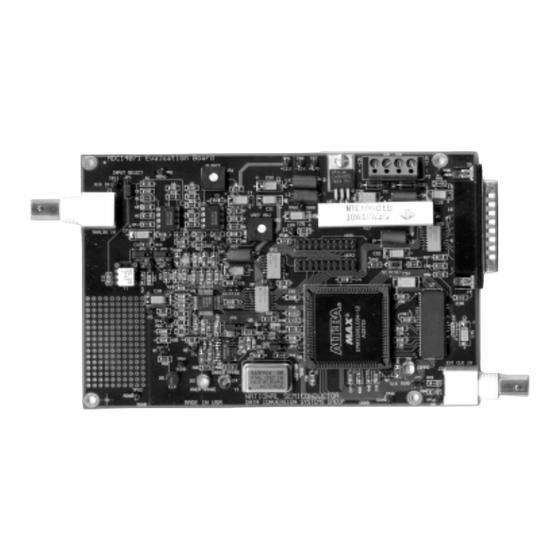
Summary of Contents for National Semiconductor ADC14071EVAL
- Page 1 National Semiconductor is now part of Texas Instruments. Search http://www.ti.com/ for the latest technical information and details on our current products and services.
- Page 2 August 2000 Rev 1 Evaluation Board Instruction Manual ADC14071 14-Bit, 7 MSPS, 390mW Analog-to-Digital Converter © 1999 National Semiconductor Corporation http://www.national.com...
- Page 3 [Blank] http://www.national.com...
-
Page 4: Table Of Contents
Table of Contents 1.0 Introduction......................................5 2.0 Quick Start ......................................5 3.0 Functional Description .................................... 5 3.1 Input signal conditioning............................... 5 3.2 ADC reference circuitry................................ 5 3.3 Board Outputs..................................6 3.4 Board Control..................................6 3.5 Data Memory..................................6 3.6 Computer Interface................................ - Page 5 [Blank] http://www.national.com...
-
Page 6: Introduction
To use the 1.0 Introduction transformer T1, place jumpers JP1, JP2 and JP3 to The ADC14071EVAL Design (consisting their default positions. When using the transformer, ADC14071 Evaluation Board, National's WaveVision the signal level at BNC J1 should be about 2V p-p . -
Page 7: Board Outputs
ADC CLK Point Reset CLK SEL Button DGND Under Over COMMO Range Range Jumper default NATIONAL SEMICONDUCTOR DGND AGND MADE IN USA DATA CONVERSION SYSTEMS GROUP TP10 positions EXT CLK Ext. Clock Input Clock Source Clock JP2 & JP4 &... -
Page 8: Software Installation
generators can not provide a level of distortion low enough to Adjust the signal source at Analog Input J1 for a signal evaluate high resolution ADCs. amplitude of approximately 2V P-P , centered at ground. Scope the signals at TP12 and TP13 to be sure they 4.1 Software Installation are present at a 2V P-P level between ground and +2V. -
Page 9: Getting Consistent Readings
PINS 1 & 2 PINS 2 & 3 JUMPER FUNCTION SHORTED SHORTED Select Select Op- Input Select Transformer Amp Circuit Select Input Select Select Op- JP2 & JP3 to drive ADC Transformer Amp Circuit Select Clock External On-Board Source Clock Clock Ext. -
Page 10: Exploring The Waveform
If the displayed waveform appears to be garbage, or if the 5.1.1 Evaluating a Sine Wave FFT plot shows nothing but noise with no apparent signal, Set the ADC clock frequency to 7MSPS as follows: reset the evaluation board by pressing button S1 and try Be sure that a 14MHz oscillator (Y1) is in its socket, or again. -
Page 11: Rising / Falling Symmetry
6.0 Computer-Board Communications Communication between the board and computer is through a parallel port connection at connector P1. The board responds to commands from the computer and uploads data requested by the computer. The RAM address is incremented by PLD U6, which clocks the ADC14071 output data into RAM. - Page 12 Computer Controller Memory Power Suply Parallel Port Control, Memory and Communications & Power Supply (Figure 9) ADC Clock Single-Ended Analog Input Differential ADC14071 Reference Ref Adj Input, Reference and Test Device (Figure 8) Figure 7. Block Diagram of the ADC14071 Evaluation Board http://www.national.com...
-
Page 13: Hardware Schematics
7.4 Hardware Schematics http://www.national.com... - Page 14 0.1uF 68uF 0.1uF CHOKE 0.1uF 0.1uF 0.1uF 0.1uF 0.1uF 0.1uF ADC[0..15] MEMORY 26 38 43 53 66 78 HDR2 ADC13 ADC13 RAMM7 ADCM7 ADC12 10uF + ADC12 ADCM6 RAMM6 ADC11 ADC11 ADCM5 RAMM5 0.1uF ADC10 0.1uF ADC10 ADCM4 RAMM4 ADC9 ADC9 ADCM3 RAMM3...
-
Page 15: Bill Of Materials
TP1, TP2, TP3, TP4, TP5, TP6, TP7, TP8, TP9, Breakable Headers DigiKey # S1012-36-ND TP10, TP11, TP12, TP13 Signal Transformer MiniCircuits type T4-6T U1, U2 LM6172 National Semiconductor LM4041-ADJ National Semiconductor ADC14071 National Semiconductor NC7S04P5 Fairchild Semiconductor EPM7128ELC84-15 (Needs programming) -
Page 16: Saving And Retrieving Files
9.1 ASCII Files 9.0 Saving and Retrieving Files To export (save) an ASCII file for use later by another WaveVision allows you to save data in two formats. One is a program, such as a spreadsheet, you must enter , F, D. binary file, the other is an ASCII file. -
Page 17: Appendix - Wavevision Screens
APPENDIX - WaveVision Screens ADC14071 WaveVision Menu & Icon Description ADC14061 / ADC14161 / ADC14071 / ADC16061 WaveVision Sample 1 File Edit View Prodecure Options Window Help (same as , P, F or CTRL Acquire & Plot Data (same as , P, X or CTRL Setup -... - Page 18 ADC14071 WaveVision Procedure Menu ADC14061 / ADC14161 / ADC14071 / ADC16061 WaveVision Sample 1 File Edit View Prodecure Options W indow Help Procedure Execute Ctrl+X Histog ram Ctrl+H Configure Board..Ctrl+P Send Config Ctrl+F ADC14061/ADC14161 / ADC14071 ADC16061 WaveVision Parallel Port Time Out Error. The evaluation board should be reset.
- Page 19 ADC14071 Sampled Data and FFT Data Display Options Sampled Data display Title: This dialog box isobtained by double clicking on the sampled X Axis Units Y Axis Units data plot. Samples Converter Codes Seconds Volts It allows you to set a title for the displayed waveform, to set X Axis Sampling Rate of Vmax...
- Page 20 [Blank] http://www.national.com...
- Page 21 European EMC Directive 89/336/EEC. WaveVision is a trademark of National Semiconductor Corporation. National does not assume any responsibility for use of any circuitry or software supplied or described. No circuit patent licenses are implied.


Need help?
Do you have a question about the ADC14071EVAL and is the answer not in the manual?
Questions and answers