
Subscribe to Our Youtube Channel
Related Manuals for Clare Controls CV-M3B10-ODI


Summary of Contents for Clare Controls CV-M3B10-ODI
- Page 1 Network Camera Installation Guide 3 MP Mainline Bullet Camera Model CV-M3B10-ODI Last modified: 09/28/16 Doc ID - 337 • REV 04...
- Page 3 © 28SEP16 Clare Controls. All rights reserved. Copyright This document may not be copied in whole or in part or otherwise reproduced without prior written consent from Clare Controls, LLC., except where specifically permitted under US and international copyright law.
-
Page 5: Table Of Contents
Content Description...1 Package contents...1 Safety instruction...1 Overview...4 Wiring...6 Installation...7 Before you start...7 Mounting...11 View angle adjusting...17 Zoom and focus adjusting...19 Setting the network camera over LAN...20 Accessing via a web browser...24 System requirements...24 Specifications...28 Regulatory information...30 Warranty information...32 Contact information...32... -
Page 7: Description
Description The 3 MP Mainline Bullet Camera is a high-resolution bullet IP camera with 3 MP. It is the appropriate choice for outdoor applications where image detail and/or wider coverage is important. Capable of 2048 × 1536 resolution, the varifocal lens incorporates 25 meter IR LEDs and zone-configurable backlight compensation for use in varying light conditions. - Page 8 WARNINGS In the use of the product, you must be in strict compliance with the electrical safety regulations of the nation and region. Refer to the technical specifications for detailed information. Input voltage should meet both the SELV (Safety Extra ...
- Page 9 CAUTIONS Make sure the power supply voltage is correct before using the camera. Do not drop the camera or subject it to physical shock. Do not touch CMOS modules with fingers. If cleaning is necessary, use a clean cloth with a bit of ethanol and wipe it gently.
-
Page 10: Overview
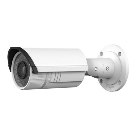
Overview Figure 1: Camera overview Sun shield Video output interface Front cover Integrated bracket Zoom and focus lever Reset button IR LED (10) SD card slot Lens (11) Power interface Air vent (12) Network intrface To reset the default parameters to the camera, press and Note: hold the reset button and power on the camera. - Page 11 The bullet camera supports audio and alarm functions. The interfaces are shown in Figure 2. Figure 2: Audio and alarm interfaces Audio Alarm...
-
Page 12: Wiring
Wiring Wire your bullet camera as shown in Figure 3. Figure 3: Wiring... -
Page 13: Installation
Installation To ensure the camera operates properly, install the camera according to the instructions below. Before you start Make sure that the device in the package is in good condition and all the assembly parts are included. Make sure that all the related equipment is powered off ... - Page 14 To mount the SD card: Rotate the TW M3 × 5 screw counterclockwise about 3 to 4 rounds to loosen it. Slide the sun shield according to the arrow direction, as shown in the figure below (left). Turn screw Remove the sun shield according to the arrow direction, as shown in above (right).
- Page 15 Remove the front cover by rotating it counterclockwise, as shown in above (right). Insert the SD card to the SD card slot. Place the cover back on the front of the camera and rotate it clockwise, as shown. Reinstall the sun shield according to the arrow direction, as shown below.
- Page 16 Rotating label For waterproofing, align the rotating label on the front Note: cover with that on the camera when you rotate the front cover clockwise.
-
Page 17: Mounting
Mounting This camera is equipped with a bracket on the bottom. It can be mounted to a wall or ceiling directly or it can be mounted to a wall with a junction box (not included) or a gang box (not included). - Page 18 Screw Hole Cable Hole 2:Screw Hole 1:Screw Hole for Mounting for Bracket Base...
- Page 19 If you need to route cables through the wall or ceiling, cut a cable hole according to the drill template. Skip this step, if you want to route the cables on the surface of the ceiling. Route the cables of the camera. Secure the camera to the wall (or ceiling) with expansion screws, as shown below.
- Page 20 To mount with a junction box: Attach the drill template to the wall where the camera is to be mounted. Drill holes in the wall according to the number two holes of the drill template. If you need to route cables through the wall, cut a cable hole according to the drill template.
- Page 21 Hook the camera to the junction box with the safety rope. Junction box Safety rope Secure the camera to the junction box with screws.
- Page 22 To mount with a gang box: Secure the camera attachment to a gang box with screws. Route the cables of the camera. Gang box Camera attachment...
-
Page 23: View Angle Adjusting
View angle adjusting The 3-axis (pan/tilt/rotation) adjusting allows adjustment for optimum camera rotation and placement. Use this function to get the angle of view that you want. To adjust pan: Loosen the lock screw-1. Adjust the panning position of the camera. The adjusting range is from 0 degrees to 360 degrees. - Page 24 Lock screw - 1 Rotation Tilt Lock screw - 2 Lock screw - 3...
-
Page 25: Zoom And Focus Adjusting
Zoom and focus adjusting You can use the zoom lever and focus lever to adjust the zoom value and focus value. To adjust zoom and focus: Disassemble the camera. View the camera image using the monitor. Loosen the zoom lever and move the lever between T (Tele) and W (Wide) to obtain the appropriate angle of view. -
Page 26: Setting The Network Camera Over Lan
Setting the network camera over To view and configure the camera via LAN (Local Area Network), you need to connect the network camera in the same subnet with your PC. Then, install the SADP software to search and change the IP of network camera. The following figure shows the cable connection of network camera and PC: Figure 4: Wiring over LAN... - Page 27 After launching the SADP software, it automatically searches the online devices every 15 seconds from the subnet where your computer is located. It displays the total number and information of the searched devices in the Online Devices interface. The interface displays the device type, IP address, port number, and gateway.
- Page 28 To modify device information: Select the device from the list, as shown below. The network parameters of the device are displayed in the Modify Network Parameters panel, as shown below. Edit the modifiable network parameters as necessary.
- Page 29 Enter the password of the admin account of the device in the Password field and click Save to save the changes. Enter the IP address of the network camera in the address field of the web browser to view the live video. Notes The default user name is “clareadmin,”...
-
Page 30: Accessing Via A Web Browser
Accessing via a web browser System requirements Operating System: Microsoft Windows XP SP1 and above version / Vista / Win7 / Server 2003 / Server 2008 32 bits CPU: Intel Pentium IV 3.0 GHz or higher RAM: 1 G or higher ... - Page 31 Notes You may need to close the web browser to finish the installation of the plug-in. Mac’s require the plug-in to be downloaded manually. See the Clare Controls ClareVision IP CCTV Dashboard to download the plug-in. Click OK.
- Page 32 Click Next. Click Finish.
- Page 33 Reopen the web browser after the installation of the plug- in and repeat steps 2 and 3 to login. For detailed instructions of further configuration, refer to Note: the Network Camera User Guide (Doc ID 343).
-
Page 34: Specifications
Specifications Camera module Image sensor 1/3 in. progressive scan CMOS Image resolution 2048 × 1536 max. Shutter time 1/25 s (1/30 s) ~ 1 /100,000 s Minimum illumination 0.7 lux at F1.2, AGC on 0 lux with IR Lens 2.8 ~ 12 mm at F1.4, angle of view: 98°... - Page 35 System compatibility ONVIF, PSIA, CGI Protocol TCP/IP, HTTP, DHCP, DNS, DDNS, RTP, RTSP, PPPoE, SMTP, NTP, SNMP, HTTPS, FTP, 802.1 ×, QoS (SIP, SRTP, IPv6 optional) Network storage NAS ( iSCSI optional) Electrical Power source 12 V DC± 10 %, PoE (802.3 af) Power consumption Max.
-
Page 36: Regulatory Information
Regulatory information DISCLAIMER Underwriters Laboratories Inc. (UL) has not tested the performance or reliability of the security or signaling aspects of this product. UL has only tested for fire, shock or casualty hazards as outlined in UL’s Standard(s) for Safety, UL60950-1. UL Certification does not cover the performance or reliability of the security or signaling aspects of this product. - Page 37 2012/19/EU (WEEE directive): Products marked with this symbol cannot be disposed of as unsorted municipal waste in the European Union. For proper recycling, return this product to your local supplier upon the purchase of equivalent new equipment, or dispose of it at designated collection points.
-
Page 38: Warranty Information
Warranty information Clare Controls offers a three (3) year limited warranty on original Clare Controls components, from the date of shipment from Clare Controls. To view complete limited warranty details, including limitations and exclusions, www.clarecontrols.com/warranty. Scan the code to view product warranty details.
Need help?
Do you have a question about the CV-M3B10-ODI and is the answer not in the manual?
Questions and answers