
Subscribe to Our Youtube Channel
Related Manuals for Clare Controls CV-M13D10-ODI


Summary of Contents for Clare Controls CV-M13D10-ODI
- Page 1 Network Camera Installation Guide 1.3 MP Mainline Dome Camera Doc ID 2014-08-340• REV 02...
- Page 2 © 08AUG14 Clare Controls, Inc. All rights reserved. Copyright This document may not be copied in whole or in part or otherwise reproduced without prior written consent from Clare Controls, Inc., except where specifically permitted under US and international copyright law.
-
Page 3: Table Of Contents
Content Description...1 Package contents...1 Safety instruction...2 Overview...4 Wiring...5 Installation...6 Before you start...6 Disassembling...6 Mounting...7 Conduit installation on the side...10 Ceiling mounting with gang box...12 Wall mounting...15 Image and focus adjusting...19 Setting the network camera over the LAN...21 Accessing via a web browser...25 System requirements...25 Specifications...30 Regulatory information...32... -
Page 5: Description
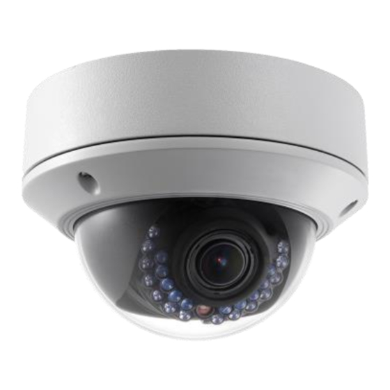
Description The 1.3 MP Mainline Dome Camera is a PoE camera for outdoor use. Capable of 1280 × 960 resolution, the camera features IR LEDs for nighttime vision up to 20 meters, and digital wide dynamic range and zone-configurable backlight compensation for best-case images in various lighting conditions. -
Page 6: Safety Instruction
Safety instruction Follow these instructions to ensure that the product is used correctly and to avoid danger or property loss. Serious injury or death may occur if any of the warnings are ignored. Injury or equipment damage may occur if any of the cautions are neglected. - Page 7 CAUTIONS Make sure the power supply voltage is correct before using the camera. Do not drop the camera or subject it to physical shock. Do not touch CMOS modules with fingers. If cleaning is necessary, use a clean cloth with a bit of ethanol and wipe it gently.
-
Page 8: Overview
Overview Figure 1: Camera overview Lower dome Power interface Black liner Ethernet interface Reset button Mounting base AUX video output interface Lens Serial port Note: To reset the default parameters to the camera, press and hold the reset button and power on the camera. After power on, continue to press and hold the reset button for another 10 seconds. -
Page 9: Wiring
Figure 2: Audio and alarm interfaces Wiring Wire your dome camera, as shown in Figure 3. Figure 3: Wiring... -
Page 10: Installation
Installation To ensure the camera operates properly, install the camera according to the instructions below. Before you start Make sure that the device in the package is in good condition and all the assembly parts are included. Make sure that all the related equipment is powered off during the installation. -
Page 11: Mounting
Loosen screws Mounting To mount on a ceiling: Disassemble the camera as described in the previous section. Attach the drill template to the place where you want to fix the camera. As shown in the drill template below, drill three screw holes in the ceiling. - Page 12 If you want to route the cables inside the ceiling, drill a cable hole in the ceiling according to the drill template. Skip this step, if you want to route the cables on the surface of the ceiling. Refer to Conduit installation on the side for side cable routing on page 10.
- Page 13 Route the cables through the cable hole. Connect the video output connector to the monitor. Connect the power connector to the power supply. Adjust the image and focus. Install the inner black liner back to the camera.
-
Page 14: Conduit Installation On The Side
Install the lower dome back to the camera and secure it with screws, as shown below. Conduit installation on the side If you want to route the cables from side of the camera, you need to follow the steps below to install a conduit for cable routing. - Page 15 Remove the waterproof plug. Route the power cable and network cable through the side outlet to the conduit. Align the conduit to the side outlet and rotate clockwise until it is tight. Note: For wall mounting, position the side outlet directly downward for waterproofing.
-
Page 16: Ceiling Mounting With Gang Box
Ceiling mounting with gang box To mount the camera on the ceiling with a gang box: Disassemble the camera. Install the gang box in the ceiling. Attach the mounting base to the gang box with two screws. - Page 17 Route the cables through the hole in the center of the mounting base. Align the camera with the mounting base. Tighten the screws to secure the camera with the mounting base. Connect the video output connector to the monitor. Connect the power connector to the power supply. Adjust the image and focus, see “Image and focus adjusting”...
- Page 18 Install the inner black liner back to the camera. Align the lower dome with the camera. Tighten the screws to secure the lower dome with the camera, as shown below.
-
Page 19: Wall Mounting
Wall mounting For the wall mounting, you have to purchase a wall mount. To mount the camera on the wall: Disassemble the camera. Install the wall mount and mounting adapter, as shown below. Align the screw holes of the mounting base with the corresponding screw holes of the mounting adapter. - Page 20 Secure the mounting base to the mounting adapter with four screws.
- Page 21 Route the cables through the hole in the center of the wall mount. Align the camera with the mounting base. Tighten the set screws to secure the camera with the mounting base. Connect the video output connector to the monitor. Connect the power connector to the power supply.
- Page 22 Camera Install the inner black liner back to the camera. Align the lower dome with the camera. Tighten the screws to secure the lower dome with the camera.
-
Page 23: Image And Focus Adjusting
Image and focus adjusting To adjust image and focus: Make the three-axis adjustment. View the camera image using the monitor. Rotate the panning table to adjust the panning position of the camera. Rotate the tilting axes to adjust the tilting position of the camera. - Page 24 Tilt Rotate To adjust zoom and focus: View the camera image using the monitor. Loosen the zoom lever and move the lever between T (Tele) and W (Wide) to obtain the appropriate angle of view. Tighten the zoom lever. Loosen the focus lever and move the lever between F (Far) and N (Near) to obtain the optimum focus.
-
Page 25: Setting The Network Camera Over The Lan
Lever Lever Setting the network camera over the LAN To view and configure the camera via LAN (Local Area Network), you will need to connect the network camera in the same subnet with your PC. Then, install the SADP software to search and change the IP of network camera. - Page 26 Figure 4: Wiring over LAN To set the IP address of the camera for accessing via LAN: To get the IP address, use the SADP, a software tool that can automatically detect network camera in the LAN and list the device information like IP address, subnet mask, port number, device serial number, and device version, shown in the figure below.
- Page 27 Notes The device can be searched and displayed in the list 15 seconds after it goes online. It is removed from the list 45 seconds after it goes offline. You can also click Refresh Every 15s to refresh the online device list manually.
- Page 28 To modify device information: Select the device to be modified from the device list, as shown below. The network parameters of the device will be displayed in the Modify Network Parameters panel on the right side, as shown below.
-
Page 29: Accessing Via A Web Browser
Edit the modifiable network parameters – for example, IP address and port number. Enter the password of the admin account of the device in the Password field and click Save to save the changes. Enter the IP address of the network camera in the address field of the web browser to view the live video. - Page 30 To access via a web browser: Open the web browser. In the browser address bar, enter the IP address of the network camera – for example, 192.168.1.250 and press Enter to display the login interface. Enter the user name and password, and then click Login. Install the plug-in before viewing the live video and managing the camera.
- Page 31 Click OK.
- Page 32 Click Next. Click Finish.
- Page 33 Reopen the web browser after the installation of the plug- in and repeat steps 2 and 3 to login. Note: For detailed instructions of further configuration, refer to the Network Camera User Guide (Doc ID 343).
-
Page 34: Specifications
Specifications Camera module Image sensor 1/3 in. Progressive scan CMOS Image resolution 1280 × 960 (max) Shutter time 1/25 s(1/30s) to 1/100,000 s Minimum illumination 0.01 lux at F1.2, AGC on 0 lux with IR Lens 2.8 to 12 mm at F1.4, Angle of view: 80°... - Page 35 SD memory Built-in Micro SD card slot, up to 32 GB Electrical Power source 12 VDC ± 10%, PoE (802.3af ) Power consumption 5.5 W (max.) Environmental Temperature -22 to 140°F (-30 to 60°C) Relative humidity 0 to 95% noncondensing Mechanical Housing IP66...
-
Page 36: Regulatory Information
Regulatory information DISCLAIMER Underwriters Laboratories Inc. (UL) has not tested the performance or reliability of the security or signaling aspects of this product. UL has only tested for fire, shock or casualty hazards as outlined in UL’s Standard(s) for Safety, UL60950-1. UL Certification does not cover the performance or reliability of the security or signaling aspects of this product. - Page 37 2012/19/EU (WEEE directive): Products marked with this symbol cannot be disposed of as unsorted municipal waste in the European Union. For proper recycling, return this product to your local supplier upon the purchase of equivalent new equipment, or dispose of it at designated collection points.
-
Page 38: Contact Information
Contact information Clare Controls, Inc. 7519 Pennsylvania Ave, Suite 104 Sarasota, FL 34243 Support: 941.404.1072 Fax: 941.870.9646 http://support.clarecontrols.com www.clarecontrols.com...
Need help?
Do you have a question about the CV-M13D10-ODI and is the answer not in the manual?
Questions and answers