
Related Manuals for Clare Controls 1.3 MP Budget Mini Bullet Camera


Summary of Contents for Clare Controls 1.3 MP Budget Mini Bullet Camera
- Page 1 Network Camera Installation Guide 1.3 MP Budget Mini-Bullet Camera Doc ID 2014-08-335 • REV 02...
- Page 3 Clare Controls, Inc., except where specifically permitted under US and international copyright law. Trademarks and The 1.3 MP Budget Mini Bullet Camera name is a patents trademark of Clare Controls, Inc. Other trade names used in this document may be trademarks or registered trademarks of the manufacturers or vendors of the respective products.
-
Page 5: Table Of Contents
Contents Description...1 Package contents...1 Safety instruction...1 Overview...4 Installation...5 Before you start...5 Setting the network camera over the LAN...8 Accessing via web browser...12 System requirement...12 Specifications...17 Regulatory information...19 Contact information...20... -
Page 7: Description
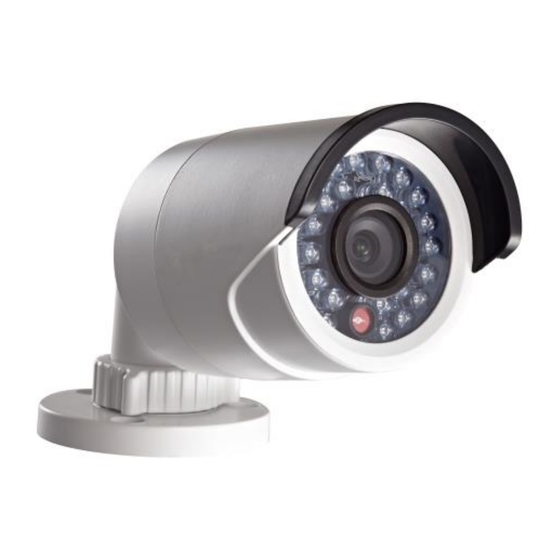
Description The 1.3 MP Budget Mini Bullet Camera is an affordable PoE 1.3 MP IP bullet camera for outdoor use. The fixed-lens camera produces 1.3 MP HD output at 1280 × 960 in low illumination with an IR LED range of 30m. Features include digital wide dynamic range, zone-configurable backlight compensation, and 3D digital noise reduction. - Page 8 WARNINGS In the use of the product, you must be in strict compliance with the electrical safety regulations of the nation and region. Refer to the technical specifications for detailed information. Input voltage should meet both the SELV (Safety Extra Low Voltage) and the Limited Power Source with 24 VAC or 12 VDC according to the IEC60950-1 standard.
- Page 9 CAUTIONS Make sure the power supply voltage is correct before using the camera. Do not drop the camera or subject it to physical shock. Do not touch CMOS modules with fingers. If cleaning is necessary, use a clean cloth with a bit of ethanol and wipe it gently.
-
Page 10: Overview
Overview Figure 1: Camera Overview Sun shield Adjustable bracket Back box Mounting base Grounding screw Reset... -
Page 11: Installation
Installation To ensure the camera operates properly, install the camera according to the instructions below. Before you start Make sure that the device in the package is in good condition and all the assembly parts are included. Make sure that all the related equipment is powered off during the installation. - Page 12 To mount the camera to a wall: Attach the drill template on the wall. Screw Hole Template Secure the camera to the wall with the supplied expansion screws.
- Page 13 Adjust the lens. Loosen the adjustable nut on the bracket. Adjust the panning angle [0 to 360°] of the camera. Adjust the tilting angle [0 to 90°] of the camera. Rotate 0 to 360° to adjust azimuth angle of the image.
-
Page 14: Setting The Network Camera Over The Lan
PC. Then install the SADP software to search and change the IP address of the network camera. The SADP software is available for download from Clare Controls at www.clarecontrols.com. The following figure shows the cable connection of a network camera and a PC. - Page 15 Figure 2: Wiring over LAN To set the IP address of the camera for accessing via LAN: To get the IP address, use the SADP. It can automatically detect the network camera in the LAN. It also lists device information like IP address, subnet mask, port number, device serial number, and device version, shown in the figure below.
- Page 16 Notes The device can be searched and displayed in the list 15 seconds after it goes online. It is removed from the list 45 seconds after it goes offline. You can click on each column heading to order the information.
- Page 17 The network parameters of the device will be displayed in the Modify Network Parameters panel on the right side, as shown below. Edit the modifiable network parameters – for example, IP address and port number.
-
Page 18: Accessing Via Web Browser
Enter the password of the admin account of the device in the Password field and click Save to save the changes. Enter the IP address of the network camera in the address field of the web browser to view the live video. Notes ... - Page 19 To access via the web browser: Open the web browser. In the browser address bar, enter the IP address of the network camera – for example, 192.168.1.250 and press Enter to display the login interface. Enter the user name and password, and then click Login.
- Page 20 Install the plug-in before viewing the live video and managing the camera. Follow the installation prompts to install the plug-in. Note: You may need to close the web browser to finish the installation of the plug-in.
- Page 21 Click OK. Click Next.
- Page 22 Click Finish. Reopen the web browser after the installation of the plug- in and repeat steps 2 and 3 to login. Note: For detailed instructions of further configuration, refer to the Network Camera User Guide (Doc ID 343).
-
Page 23: Specifications
Specifications Camera module Image Sensor 1/3 in. progressive scan CMOS Image Resolution 1280 × 960 max. Shutter Time 1/25 s (1/30 s) ~ 1/100,000 s Illumination 0.1 lux at F1.2, AGC on 0 lux with IR (min.) Lens 4 mm at F2.0, angle of view: 73.1° (6 mm, 12 mm optional) Day and Night IR cut filter with auto switch... - Page 24 System compatibility ONVIF, PSIA, CGI TCP/IP, HTTP, DHCP, DNS, DDNS, RTP, Protocol RTSP, PPPoE, SMTP, NTP, SNMP, HTTPS, FTP, 802.1 ×, QoS (SIP, SRTP, IPv6 optional) SD memory Built-in Micro SD card slot, up to 32 GB Electrical Power source 12 V DC ±...
-
Page 25: Regulatory Information
Regulatory information DISCLAIMER Underwriters Laboratories Inc. (UL) has not tested the performance or reliability of the security or signaling aspects of this product. UL has only tested for fire, shock or casualty hazards as outlined in UL’s Standard(s) for Safety, UL60950-1. UL Certification does not cover the performance or reliability of the security or signaling aspects of this product. -
Page 26: Contact Information
(Cd), lead (Pb), or mercury (Hg). For proper recycling, return the battery to your supplier or to a designated collection point. For more information see www.recyclethis.info. Contact information Clare Controls, Inc. 7519 Pennsylvania Ave, Suite 104 Sarasota, FL 34243 Support: 941.404.1072 Fax: 941.870.9646 http://support.clarecontrols.com www.clarecontrols.com...
Need help?
Do you have a question about the 1.3 MP Budget Mini Bullet Camera and is the answer not in the manual?
Questions and answers