
Subscribe to Our Youtube Channel
Related Manuals for Mercury GO BOLDLY 25 EFI


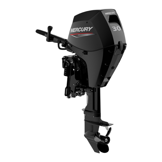
Summary of Contents for Mercury GO BOLDLY 25 EFI
- Page 1 Operation Maintenance Installation Manual Scan for service and support information...
- Page 3 Keep this manual with the product for ready reference whenever you are on the water. Thank you for purchasing one of our products. We sincerely hope your boating will be pleasant. Mercury Marine, Fond du Lac, Wisconsin, U.S.A. Name / function: Christopher D. Drees, President, Mercury Marine...
- Page 4 The product you have purchased comes with a Mercury Marine Limited Warranty. The terms of the warranty are set forth in the Warranty Manual, which can be accessed any time on the Mercury Marine website, at http:// www.mercurymarine.com/warranty‑manual. The Warranty Manual contains a...
- Page 5 In addition, certain Mercury Marine products are tested in a controlled and monitored environment, for up to 10 hours of engine run time, in order to verify and make a record of compliance with applicable standards and regulations.
-
Page 7: Table Of Contents
General Information Boater's Responsibilities..................1 Outboard Remote Control Models ..............1 Exhaust Emissions..................... 1 Lanyard Stop Switch................... 3 Protecting People in the Water................5 Passenger Safety Message ‑ Pontoon Boats and Deck Boats......6 Wave and Wake Jumping................... 7 High‑Speed and High‑Performance Boat Operation.......... 8 Impact with Underwater Hazards................ - Page 8 Fuel and Oil Low Permeation Fuel Hose Requirement ............49 Fuel Demand Valve (FDV) Requirement............49 EPA Pressurized Portable Fuel Tank Requirements........49 Mercury Marine's Pressurized Portable Fuel Tank........... 49 Filling Fuel Tank....................51 Fuel Requirements................... 51 Engine Oil Recommendations................52 Features and Controls Tiller Handle Features..................
- Page 9 Maintenance Cleaning Care....................85 EPA Emissions Regulations................87 Inspection and Maintenance Schedule............. 88 Maintenance Schedule Decal Icons ..............89 Maintenance Schedule Decal................90 Top Cowl Removal and Installation..............90 Cooling System....................90 Corrosion Control Anode.................. 92 Engine Oil......................94 Fuel System...................... 98 Gearcase Lubrication..................
- Page 10 Maintenance Log Maintenance Log.................... 123 viii...
-
Page 11: General Information
GENERAL INFORMATION Boater's Responsibilities The operator (driver) is responsible for the correct and safe operation of the boat and the safety of its occupants and general public. It is strongly recommended that each operator read and understand this entire manual before operating the outboard. - Page 12 GENERAL INFORMATION WARNING Inhaling engine exhaust gases can result in carbon monoxide poisoning, which can lead to unconsciousness, brain damage, or death. Avoid exposure to carbon monoxide. Stay clear from exhaust areas when engine is running. Keep the boat well‑ventilated while at rest or underway. STAY CLEAR OF EXHAUST AREAS 41127 Engine exhaust gases contain harmful carbon monoxide.
-
Page 13: Lanyard Stop Switch
GENERAL INFORMATION Although the occurrence is rare, on a calm day, swimmers and passengers in an open area of a stationary boat that contains, or is near, a running engine may be exposed to a hazardous level of carbon monoxide. 1. - Page 14 GENERAL INFORMATION The lanyard cord is usually 122–152 cm (4–5 feet) in length when stretched out, with an element on one end made to be inserted into the switch and a clip on the other end for attaching to the operator's PFD or wrist. The lanyard is coiled to make its at‑rest condition as short as possible to minimize the likelihood of lanyard entanglement with nearby objects.
-
Page 15: Protecting People In The Water
GENERAL INFORMATION WARNING If the operator falls out of the boat, stop the engine immediately to reduce the possibility of serious injury or death from being struck by the boat. Always properly connect the operator to the stop switch using a lanyard. WARNING Avoid serious injury or death from deceleration forces resulting from accidental or unintended stop switch activation. -
Page 16: Passenger Safety Message - Pontoon Boats And Deck Boats
GENERAL INFORMATION Approach slowly and exercise extreme caution when boating in areas where people may be in the water. When a boat is moving and the gear shift is in neutral, there is sufficient force by the water on the propeller to cause the propeller to rotate. This neutral propeller rotation can cause serious injury. -
Page 17: Wave And Wake Jumping
GENERAL INFORMATION WARNING Sitting or standing in an area of the boat not designed for passengers at speeds above idle can cause serious injury or death. Stay back from the front end of deck boats or raised platforms and remain seated while the boat is in motion. -
Page 18: High-Speed And High-Performance Boat Operation
For additional information, obtain a copy of our Hi‑Performance Boat Operation booklet from your dealer, distributor, or Mercury Marine. Impact with Underwater Hazards Your outboard may be equipped with a hydraulic trim and tilt system that also contains a shock absorbing feature. - Page 19 GENERAL INFORMATION Reduce speed and proceed with caution whenever you drive a boat in shallow water areas or in areas where you suspect underwater obstacles may exist that could be struck by the outboard or the boat bottom. The most significant action you can take to help reduce injury or impact damage from striking a floating or underwater object is to control the boat speed.
-
Page 20: Safety Instructions For Hand-Tilled Outboards
Operating a boat or engine with impact damage can result in product damage, serious injury, or death. If the vessel experiences any form of impact, have an authorized Mercury Marine dealer inspect and repair the vessel or power package. Safety Instructions for Hand‑Tilled Outboards No person or cargo should occupy the area directly in front of the outboard while the boat is in motion. -
Page 21: Safe Boating Recommendations
GENERAL INFORMATION Safe Boating Recommendations To safely enjoy the waterways, familiarize yourself with local and all other governmental boating regulations and restrictions and consider the following suggestions. Know and obey all nautical rules and laws of the waterways. • We recommend that all powerboat operators complete a boating safety course. - Page 22 (refer to your boat's capacity plate). Know your boat's operating and loading limitations. Know if your boat will float if it is full of water. When in doubt, contact your authorized Mercury Marine dealer or the boat manufacturer. Ensure that everyone in the boat is properly seated.
-
Page 23: Conditions Affecting Performance
All values are corrected to the power the engine will produce at sea level, at 30% relative humidity, at 25 °C (77 °F) temperature, and a barometric pressure of 29.61 inches of mercury (in. Hg). Summer conditions of high temperature, low barometric pressure, and high humidity all combine to reduce the engine power. - Page 24 GENERAL INFORMATION • At extremes, can cause the boat to porpoise Shifting weight to front (bow): • Improves ease of planing • Improves rough water ride • At extremes, can cause the boat to veer back and forth (bow steer) BOTTOM OF BOAT For maximum speed, a boat bottom should be nearly a flat plane where it contacts the water and particularly straight and smooth in fore and aft direction.
- Page 25 RPM range, normal engine operation resumes. The boat manufacturer and the selling dealer are responsible for equipping the power package with the correct propeller. Refer to Mercury Marine's web page https://www.mercurymarine.com/en/us/propellers/selector/#/step‑one. Select a propeller that will allow the engine power package to operate at or near the top end of the recommended WOT operating RPM range with a normal load.
-
Page 26: Recording Serial Number
Record the engine's serial number for future reference. The serial number is located on the outboard as shown. Serial number Model Number XXXXXXX Model designation Serial Number Year manufactured XXXXX XX XXXX XXX Certified Europe Insignia (as applicable) Mercury Marine Brunswick Corp. Made in Japan CAN ICES-2 / NMB-2 74489... -
Page 27: Model Year Production Code
Model Number XXXXXXX Serial Number XXXXX XX XXXX XXX Mercury Marine Brunswick Corp. Made in Japan CAN ICES-2 / NMB-2 70058 Serial number decal alpha code Model Year Manufactured Code... -
Page 28: Component Identification
GENERAL INFORMATION Component Identification POWER TRIM MODEL 74282... - Page 29 GENERAL INFORMATION Top cowl Oil drain screw Tilt support lever Water pump indicator hole Transom brackets Auxiliary trim/tilt switch Anti‑ventilation plate Port lower cowl Primary cooling water intake Starboard lower cowl Gearcase Cowl latch Secondary cooling water intake Manual tilt release valve (accessible through port transom bracket)
- Page 30 GENERAL INFORMATION MANUAL GAS ASSIST TILT MODEL 74388...
- Page 31 GENERAL INFORMATION Top cowl Tilt support lever Manual start handle Primary cooling water intake Shift lever Gearcase Throttle grip Secondary cooling water intake Engine stop switch Anti‑ventilation plate Throttle friction adjustment knob Oil drain screw Lanyard stop switch (lanyard Water pump indicator hole cord not shown) Lower cowls Steering friction adjustment...
- Page 32 GENERAL INFORMATION MANUAL TILT MODEL 74281...
-
Page 33: Specifications
GENERAL INFORMATION Top cowl Tiller handle tilt lock lever Manual start handle Steering friction adjustment lever Shift lever Primary cooling water intake Throttle grip Gearcase Engine stop switch Secondary cooling water intake Throttle friction adjustment knob Anti‑ventilation plate Lanyard stop switch (lanyard cord not shown) Oil drain screw Transom brackets... - Page 34 GENERAL INFORMATION Parameter Specification Gear ratio 2.17:1 Premium Gear Lubricant or SAE 80W‑90 Gear lubricant type API GL‑4 Gearcase lubricant capacity 460 ml (15.6 fl oz) Electronic engine control (EC) Emission control system Multiport fuel injection (MFI)
-
Page 35: Installation
Some accessories not manufactured or sold by Mercury Marine are not designed to be safely used with your outboard or outboard operating system. Acquire and read the installation, operation and maintenance manuals for all... - Page 36 When installing the boat's fuel system, refer to Fuel and Oil for fuel system requirements: • Low Permeation Fuel Hose Requirement • Fuel Demand Valve (FDV) Requirement • EPA Pressurized Portable Fuel Tank Requirements • Mercury Marine's Pressurized Portable Fuel Tank...
- Page 37 INSTALLATION MERCURY MARINE VALIDATED ENGINE MOUNTING HARDWARE IMPORTANT: Mercury Marine provides validated fasteners and installation instructions, including torque specifications, with all of our outboards so they can be properly secured to boat transoms. Improper installation of the outboard can cause performance and reliability issues that can lead to safety concerns.
-
Page 38: Installing The Outboard
INSTALLATION Installing the Outboard INSTALLATION SPECIFICATIONS 2763 Minimum transom opening Engine centerline for dual engines Minimum Transom Opening Single engine (remote) 48.3 cm (19 in.) Single engine (tiller) 76.2 cm (30 in.) Dual engines 101.6 cm (40 in.) Engine Centerline Minimum 66 cm (26 in.) LIFTING THE OUTBOARD... - Page 39 INSTALLATION INSTALLING THE OUTBOARD ON THE TRANSOM (MANUAL TILT MODELS) WARNING Failure to correctly fasten the outboard could result in the outboard propelling off the boat transom resulting in property damage, serious injury, or death. Before operation, the outboard must be correctly installed with the required mounting hardware.
- Page 40 INSTALLATION 2. Tighten the transom clamp bolts. 74492 3. Use a long drill bit to drill the two lower 8 mm (0.315 in.) holes through the transom, using the transom clamps as a template for the bolt hole pattern. Upper transom clamp hole Lower transom clamp hole 15949 4.
- Page 41 INSTALLATION INSTALLING THE OUTBOARD ON THE TRANSOM (POWER TRIM AND GAS ASSIST) WARNING Failure to correctly fasten the outboard could result in the outboard propelling off the boat transom resulting in property damage, serious injury, or death. Before operation, the outboard must be correctly installed with the required mounting hardware.
- Page 42 INSTALLATION When first determining transom strength, use a dial torque wrench. If the bolt or nut continues to turn without the torque reading on the dial increasing, it is an indication that the transom is yielding. The load area can be increased by using a larger washer or a transom reinforcement plate.
- Page 43 INSTALLATION Transom Drilling Fixture 91‑98234A2 Aids in engine installation by acting as a template for engine mounting holes. 5489 2. Drill four 13.5 mm (17/32 in.) mounting holes. 3973 3. Install the outboard so that the anti‑ventilation plate is in‑line or within 25 mm (1 in.) of the bottom of the boat.
-
Page 44: Remote Control Connections
INSTALLATION The outboard must be secured to the transom with the two transom bracket clamp screws and four 13 mm (1/2 in.) diameter mounting bolts and locknuts provided. Install two bolts through the upper set of mounting holes and two bolts through the lower set of mounting slots. - Page 45 INSTALLATION 3. Route the harness along the top and forward sides of the intake runner, and secure the harness with cable ties in three locations. 74441 14‑pin connector Cable ties Remote harness THROTTLE CABLE INSTALLATION - RC MODELS Install cables into the remote control following the instructions provided with the remote control.
- Page 46 INSTALLATION 3. Adjust the throttle cable barrel so that when the barrel is installed into the barrel support bracket, no play can be felt when lightly pushing the throttle cam with a finger. 74479 Throttle actuating lever Cotter pin Plastic washer Throttle cam (no play can be felt when lightly pushing) Throttle cable barrel Barrel support bracket...
- Page 47 INSTALLATION c. Make a center mark ("c"), midway between marks "a" and "b". Align the cable end guide with this center mark when connecting the cable to the engine. 6098 2. Ensure that both the outboard engine and the remote control are in neutral.
- Page 48 INSTALLATION a. Shift remote control into forward. The propeller shaft should be locked in gear. If not, adjust the cable end accordingly. b. Shift remote control into reverse while turning propeller. The propeller shaft should be locked in gear. If not, adjust the cable end accordingly. Repeat steps a through c.
-
Page 49: Steering Control Connections
INSTALLATION Description lb‑in. lb‑ft Captive screw (7) – 9. Use cable ties to secure the throttle, shift, and battery cables to the boat harness, to prevent contact with the steering components. 74478 Steering Control Connections STEERING BRACKET, STEERING CABLE INSTALLATION 1. - Page 50 INSTALLATION 4. Insert the steering cable into the tilt tube and secure with the steering cable nut. Tighten the steering cable nut to the specified torque. 59494 Steering cable nut Steering bracket bolt and washer (2) Steering cable seal Description lb‑in.
- Page 51 INSTALLATION 1. Install the steering link rod onto the steering bracket aft threaded hole. 59496 2. Assemble the steering link rod onto the steering bracket with the screw, two washers, spacer, and a locknut. Do not tighten the screw or locknut. 59497 Screw Washer...
-
Page 52: Battery Cable Connections
INSTALLATION 3. Install the loose end of the steering link onto the steering cable and secure with a washer and locknut. Tighten the locknut securely and then back the nut off 1/4 turn. Washer Locknut 59499 4. Tighten the link rod screw to the specified torque. 5. - Page 53 INSTALLATION SINGLE OUTBOARD Red sleeve ‑ positive Black sleeve ‑ negative (–) Cranking battery 15496 DUAL OUTBOARDS Connect a common ground cable (wire size same as engine battery cables) between negative (–) terminals on starting batteries. 15497 Red sleeve ‑ positive (+) Black sleeve ‑...
-
Page 54: Installing The Propeller
INSTALLATION Installing the Propeller WARNING Rotating propellers can cause serious injury or death. Never operate the boat out of the water with a propeller installed. Before installing or removing a propeller, place the drive unit in neutral and activate the lanyard stop switch to prevent the engine from starting. - Page 55 INSTALLATION 5. Place a block of wood between the gearcase and the propeller and torque the propeller nut to specification. NOTE: If the propeller nut does not align with the propeller shaft hole after tightening to the specified torque, then tighten the nut further to align it with the hole in the propeller shaft.
-
Page 56: Transporting
TRANSPORTING Aquatic Invasive Species (AIS) STOP AQUATIC HITCHHIKERS!™ Be A Good Steward. Clean. Drain. Dry. For additional information, visit StopAquaticHitchhikers.org. 68805 AIS and their spread can detrimentally impact the boating experience and the future of the boating lifestyle. Reducing the spread of AIS has led to significant national efforts to inspect boats moving between water bodies or across state and federal boundaries and could lead to delayed or denied access if AIS are suspected or found on board. -
Page 57: Carrying, Storing, And Transporting The Outboard When Removed From Boat
TRANSPORTING If additional ground clearance is required, the outboard should be tilted up using an accessory outboard support device. Refer to your local dealer for recommendations. Additional clearance may be required for railroad crossings, driveways, and trailer bouncing. 74512 IMPORTANT: Do not rely on the power tilt system or the tilt support lever to maintain proper ground clearance for trailering. - Page 58 TRANSPORTING • An upright position 74336 Upright position • On the port side. The port side lower cowl has two bumpers to help reduce damage to the cowl when the engine is stored laying down. Storing the engine on the port side will prevent oil from draining out of the crankcase into the cylinders or crankcase ventilation system.
-
Page 59: Fuel And Oil
34.4 kPa (5.0 psi). Mercury Marine's Pressurized Portable Fuel Tank Mercury Marine has created a new portable pressurized fuel tank that meets the preceding EPA requirements. These fuel tanks are available as an accessory or are provided with certain portable outboard models. - Page 60 FUEL AND OIL • The fuel tank includes a fuel demand valve that prevents pressurized fuel from entering the engine and causing a fuel system overflow or possible fuel spillage. • When installing the fuel tank cap, turn the cap to the right until you hear a click.
-
Page 61: Filling Fuel Tank
USA is alcohol (ethanol, methanol, or butanol). GASOLINE CONTAINING ALCOHOL Bu16 Butanol Fuel Blends Fuel blends of up to 16.1% butanol (Bu16) that meet the published Mercury Marine fuel rating requirements are an acceptable substitute for unleaded gasoline. Contact your boat manufacturer for specific recommendations on... -
Page 62: Engine Oil Recommendations
As an optional choice, Mercury or Quicksilver SAE 25W‑40 Mineral Marine 4‑Stroke Engine Oil or SAE 25W‑40 Synthetic Blend Marine 4‑Stroke engine oil may be used. If the recommended Mercury or Quicksilver NMMA FC‑W certified oils are not available, a major outboard manufacturer's brand of NMMA FC‑W certified 4‑Stroke outboard oil of similar... - Page 63 FUEL AND OIL IMPORTANT: Nondetergent oils, multiviscosity oils (other than Mercury or Quicksilver NMMA FC‑W certified oil or a major brand NMMA FC‑W certified oil), full synthetic oils, low quality oils, and oils that contain solid additives are not recommended.
-
Page 64: Features And Controls
FEATURES AND CONTROLS Tiller Handle Features • A decal on the tiller handle provides a quick reference for starting the engine. • Throttle grip friction knob ‑ Turn the friction knob to set and maintain the throttle at desired speed. Turn the knob clockwise to increase the friction or turn the knob counterclockwise to decrease the friction. - Page 65 FEATURES AND CONTROLS • Tiller handle adjustment knob ‑ Turn the adjustment knob to raise or lower the tiller handle in its operating position. Tiller lock release lever Tiller handle adjustment knob 74496 a. Adjustment knob at the lowest setting. 74497 b.
- Page 66 FEATURES AND CONTROLS b. Loosen the 15 mm nut so it is almost completely off. Clamp screw nut Rubber boot 74499 c. Loosen the 6 mm Allen socket head pivot screw. 63259 6 mm Allen socket head pivot screw d. Lift the clamp with your fingers and rotate the tiller handle to the desired angle.
- Page 67 FEATURES AND CONTROLS e. Tighten the clamp screw nut to the specified torque and install the rubber boot. Description lb‑in. lb‑ft Clamp screw nut – 36.8 f. Tighten the 6 mm Allen socket head pivot screw to the specified torque. Description lb‑in.
- Page 68 FEATURES AND CONTROLS • Throttle grip ‑ Controls the engine speed. Align the throttle grip with the idle mark on the tiller handle when starting or shifting into or out of gear. Twist the throttle grip to increase the engine speed. 63086 •...
-
Page 69: Remote Control Features
FEATURES AND CONTROLS Remote Control Features Your boat may be equipped with one of the Mercury Precision or Quicksilver remote controls shown. Consult your dealer for a description of the functions and operations of other remote controls. 58240 Trim switch Ignition key switch—OFF, ON, START... -
Page 70: Tiller Handle Models With Manual Gas Assist Tilt
FEATURES AND CONTROLS Tiller Handle Models with Manual Gas Assist Tilt WARNING Operating the engine without engaging the tilt lock lever can cause serious injury or death. The outboard can tilt upwards when decelerating or operating in reverse, causing loss of boat control. Always lock the outboard in its run position before operating. - Page 71 FEATURES AND CONTROLS SHALLOW WATER OPERATION When operating the boat in shallow water, the outboard can be adjusted and locked at a higher tilt angle. Operate the outboard at slow speed while tilted up for shallow water operation. Keep the cooling water intake holes submerged in the water, and continue to check for water discharge from the water pump indicator hole.
- Page 72 FEATURES AND CONTROLS 2. Move the lock lever to the lock position. 9703 OPERATING ANGLE ADJUSTMENT The transom brackets have four holes for adjusting the vertical operating angle (forward stop movement) of the outboard. Use the tilt pin for adjustments in the four holes.
- Page 73 FEATURES AND CONTROLS Arrange passengers and the load in the boat so the weight is distributed evenly. 74515 Too much angle (bow up) ‑ adjust in Not enough angle (bow down) ‑ adjust out Angle adjusted properly (bow slightly up) NOTE: The outboard should be locked against the tilt pin during operation, by setting the tilt lock lever to the lock position.
-
Page 74: Tiller Handle Models With Manual Tilt
FEATURES AND CONTROLS • Increase clearance over submerged objects or a shallow bottom • Increase steering torque or pull to the left at a normal installation height (with the normal right‑hand rotation propeller) • In excess, cause boat porpoising (bouncing) or propeller ventilation Tiller Handle Models with Manual Tilt BASIC TILTING OPERATION The tilt feature allows the operator to tilt the outboard to a higher tilt angle for... - Page 75 FEATURES AND CONTROLS LOWERING OUTBOARD DOWN TO RUN POSITION Position the tilt lever in the release position. Raise the outboard slightly, to release it from its locked position, and gently lower it. SHALLOW WATER OPERATION The shallow water drive position on the outboard allows the outboard to be positioned at a higher tilt angle, to prevent hitting bottom.
- Page 76 FEATURES AND CONTROLS Arrange the passengers and load in the boat so the weight is distributed evenly. 74517 Too much angle (stern down ‑ bow up) Not enough angle (stern up ‑ bow down) Angle adjusted properly (bow slightly up) Consider the following items carefully, when adjusting the operating angle of your outboard.
-
Page 77: Power Trim And Tilt (If Equipped)
FEATURES AND CONTROLS • In excess, cause boat porpoising (bouncing) or propeller ventilation Power Trim and Tilt (if Equipped) Power trim allows the operator to easily adjust the position of the outboard by pressing the trim switch. Trim generally refers to the adjustment of the outboard within the first 20° range of travel. - Page 78 FEATURES AND CONTROLS WARNING Trimming the outboard beyond a neutral steering condition may result in a pull on the steering wheel or tiller handle and loss of boat control. Maintain control of the boat if trimming beyond a neutral steering condition. Consider the following lists carefully.
- Page 79 FEATURES AND CONTROLS 1. Engage the tilt support lever by rotating the lever down. 2. Lower the outboard to rest on the tilt support lever. 3. Disengage the tilt support lever, by slightly tilting up the outboard and releasing the tilt support bracket. Lower the outboard. 9703 MANUAL TILTING If the outboard cannot be tilted using the power trim/tilt switch, the outboard can...
-
Page 80: Warning System
FEATURES AND CONTROLS AUXILIARY TILT SWITCH The auxiliary tilt switch can be used to tilt the outboard up or down using the power trim system. 74338 SHALLOW WATER OPERATION When operating your boat in shallow water, you can tilt the outboard beyond the maximum trim range to prevent hitting bottom. - Page 81 FEATURES AND CONTROLS Function Warning Horn Description Rev Limit Engine speed will be Sensor (ECT or Intermittent short limited. Consult your 2800 RPM MAP) error beep dealer for assistance. ENGINE OVERHEAT If the engine overheats, immediately reduce throttle speed to idle. Shift outboard into neutral and check for a steady stream of water coming out of the water pump indicator hole.
-
Page 82: Trim Tab Adjustment
FEATURES AND CONTROLS • Tilting the outboard out beyond a vertical position • Cavitation of the propeller due to rough water or obstruction in the boat hull When the engine overspeed limiter is activated, the engine timing will be momentarily retarded to decrease the engine speed. Excessive overspeed (above 6300 RPM) will result in cutout of the cylinders to prevent operation above this limit. -
Page 83: Operation
OPERATION Engine Break‑in Procedure IMPORTANT: Failure to follow the engine break‑in procedures can result in poor performance throughout the life of the engine and can cause engine damage. Always follow break‑in procedures. 1. For the first two hours of operation, run the engine at varied throttle settings up to 4500 RPM or three‑quarter throttle. -
Page 84: Starting The Engine - Remote Control Models
OPERATION 2. Check the engine oil level. 73881 NOTICE Without sufficient cooling water, the engine, the water pump, and other components will overheat and suffer damage. Provide a sufficient supply of water to the water inlets during operation. 3. Make sure the cooling water intake is submerged. 26837 Starting the Engine ‑... - Page 85 OPERATION 2. Position the fuel line primer bulb so the arrow on the side of the bulb is pointing up. Squeeze the fuel line primer bulb several times until it feels firm. 27348 3. Set the lanyard stop switch to the RUN position. Refer to General Information ‑...
-
Page 86: Starting The Engine - Tiller Handle Models
OPERATION 5. Turn the ignition key to the START position and start the engine. If the engine fails to start in ten seconds, wait 30 seconds and try again. If the engine begins to stall, use the throttle‑only feature and advance the throttle. - Page 87 OPERATION 1. Open the fuel tank vent screw on the manual venting type tanks. Fuel cap Manual vent screw Tab lock 46290 IMPORTANT: To prevent engine flooding, do not squeeze the primer bulb after the engine has warmed up. 2. Position the fuel line primer bulb so the arrow on the side of the bulb is pointing up.
- Page 88 OPERATION 4. Verify the shift handle is in the neutral (N) position. 74495 5. Verify the throttle grip is set to the idle position. 63086 6. Manual starting models ‑ Pull the starter rope slowly until you feel the starter engage, then pull rapidly to crank the engine. Allow rope to return slowly.
-
Page 89: Gear Shifting
OPERATION 8. Flooded engine ‑ If the engine will not start, advance the throttle grip slightly and attempt to start the engine. After the engine has started, immediately reduce the throttle speed to idle. 9. Check for a steady stream of water flowing out of the water pump indicator. -
Page 90: Stopping The Engine
OPERATION • Tiller handle models ‑ Three gear shift positions provide boat operation: forward (F), neutral (N), and reverse (R). When shifting, always stop at the neutral position and allow the engine speed to return to idle. 74495 • Remote control models ‑ Three gear shift positions provide boat operation: forward (F), neutral (N), and reverse (R). -
Page 91: Emergency Starting Procedure
OPERATION • Tiller handle models ‑ Reduce the engine speed, and shift the outboard to neutral. Push in the engine stop button or turn the ignition key OFF. 74501 Emergency Starting Procedure If the starter system fails, use the tools provided with the engine to remove the recoil assembly (manual start models) or the flywheel cover (electric start models), and then use the provided emergency starter rope to start the engine. - Page 92 OPERATION b. Lift the neutral interlock cable out of the clip on the recoil housing. 74069 Screws with washers (3) Clip securing neutral interlock cable c. Pull and lift the neutral interlock cable to disengage it from the recoil housing. d.
- Page 93 OPERATION a. Remove the three screws with washers securing the flywheel cover to the top of the engine. Screws with washers Flywheel cover 74314 b. Remove the flywheel cover from the engine. 3. Shift the outboard into neutral. 4. Ensure that the lanyard stop switch is in the RUN position. 5.
-
Page 94: Operating In Freezing Temperatures
Wash the outboard exterior and flush out the exhaust outlet of the propeller and gearcase with fresh water after each use. Each month, spray Mercury Precision or Quicksilver Corrosion Guard on external metal surfaces. Do not spray on... -
Page 95: Cleaning Care
Record maintenance performed in the Maintenance Log at the back of this book. Save all maintenance work orders and receipts. Selecting Replacement Parts For Your Outboard We recommend using original Mercury Precision or Quicksilver replacement parts and Genuine Lubricants. DO NOT USE CAUSTIC CLEANING CHEMICALS IMPORTANT: Do not use caustic cleaning chemicals on the outboard power package. - Page 96 Keep water spray out of the air filter/intake and alternator. After washing, allow the powerhead and components to dry. Apply Quicksilver or Mercury Precision Lubricants Corrosion Guard spray on the external metal surfaces of the powerhead and powerhead components. Do not allow the Corrosion Guard spray to come in contact with the alternator drive belt or belt pulleys.
-
Page 97: Epa Emissions Regulations
EPA Emissions Regulations All new outboards manufactured by Mercury Marine are certified to the United States Environmental Protection Agency, as conforming to the requirements of the regulations for the control of air pollution from new outboard motors. This certification is contingent on certain adjustments set to factory standards. -
Page 98: Inspection And Maintenance Schedule
MAINTENANCE The owner/operator is not to modify the engine in any manner that would alter the horsepower or allow emission levels to exceed their predetermined factory specifications. Inspection and Maintenance Schedule Refer to the table below for proper inspections and maintenance intervals. After each use of the outboard be sure to: •... -
Page 99: Maintenance Schedule Decal Icons
MAINTENANCE Dealer 3 Year or 300 Hour Maintenance Item Replace the spark plugs. Refer to Spark Plug Inspection and Replacement. Inspect the timing belt. Inspect the wire harness connectors. Check the remote control cable adjustment, if equipped. Check the power trim fluid level, if equipped. Inspect the engine mounts. -
Page 100: Maintenance Schedule Decal
MAINTENANCE Maintenance Schedule Decal 74462 Top Cowl Removal and Installation TOP COWL REMOVAL 1. Unlock the cowl latch located at the rear of the engine by lifting the latch 2. Lift up on the rear of the cowl and disengage the front hook. 74510 TOP COWL INSTALLATION 1. - Page 101 MAINTENANCE Use a Mercury Precision or Quicksilver accessory (or equivalent) flushing attachment. IMPORTANT: The engine must be run during flushing in order to open the thermostat and circulate water through the water passages. WARNING Rotating propellers can cause serious injury or death. Never operate the boat out of the water with a propeller installed.
-
Page 102: Corrosion Control Anode
MAINTENANCE 2. Attach a water hose to the flushing attachment. Turn on the water and adjust the flow so water is leaking around the rubber cups to ensure the engine receives an adequate supply of cooling water. 27259 3. Start the engine and run it at idle speed in neutral shift position. IMPORTANT: Do not run the engine above idle when flushing. - Page 103 MAINTENANCE The trim tab is an anode. Trim tab 10236 Additional anodes are located on the transom bracket, lower engine mount, and swivel bracket. The number and location of the anodes depends on the model. • Manual tilt models have three additional anodes. 74439 Manual tilt model Anode on lower engine mount...
-
Page 104: Engine Oil
MAINTENANCE Engine Oil CHECKING AND ADDING ENGINE OIL IMPORTANT: Do not overfill. Be sure that the outboard is upright (not tilted) when checking oil. NOTE: Under certain conditions, the operating temperature of 4‑stroke outboard engines may not get hot enough to evaporate the normal fuel and moisture that accumulate in the crankcase. - Page 105 9.9 hp to 150 hp. These kits contain a new filter, oil, and any additional parts required for a complete oil change. The kits are available in both Mercury Marine and Quicksilver brands. Refer to the following chart for details.
- Page 106 MAINTENANCE 3. Remove the oil filter by turning the filter counterclockwise. 74049 Oil filter Oil filter drain 4. Clean the mounting base. Apply a film of clean oil to the filter gasket. Do not use grease. Install the new filter. When the gasket contacts the base, tighten the filter an additional 3/4 to 1 turn.
- Page 107 MAINTENANCE 5. Inspect the drain plug seal and replace it if it is damaged. Lubricate the seal on the drain plug with oil and install. Tighten to the specified torque. 4537 74050 Description lb‑in. lb‑ft Drain plug 24.0 – 17.7 FILLING THE CRANKCASE WITH OIL IMPORTANT: Do not try to fill the oil level to the top of the operating range (upper hole).
-
Page 108: Fuel System
MAINTENANCE 3. Install the oil fill cap. 73882 Oil fill cap Dipstick Oil level operating range 4. With cooling water properly supplied, idle the engine for five minutes and check for leaks. Stop the engine and check the oil level on the dipstick. Add oil if necessary. - Page 109 MAINTENANCE DRAINING WATER FROM THE FUEL FILTER Check the fuel filter for water accumulation or sediment. If water is in the fuel, drain the water. If the filter appears to be contaminated, remove and replace. 1. Read Fuel System Precautions, preceding. 2.
- Page 110 MAINTENANCE FUEL FILTER REPLACEMENT Filter Removal 1. Pull the filter assembly—including the rubber mount—off of the mounting bracket on the engine, and swing the assembly over the edge of the engine cowl. Fuel filter assembly installed on engine Mounting bracket Rubber mount 74507 2.
- Page 111 MAINTENANCE IMPORTANT: The filter is secured and sealed to the filter housing with an O‑ring. The O‑ring may remain on the filter housing. The O‑ring should be removed before installing the fuel filter. 63112 Fuel filter Filter Installation 63113 Fuel filter O‑ring seal Fuel filter Red ring Sight bowl O‑ring seal...
- Page 112 MAINTENANCE 1. Install the fuel filter O‑ring seal into the fuel filter. Verify the O‑ring does not have any folds or kinks. 63114 2. Lubricate the O‑ring with clean engine oil. 3. Push the fuel filter element onto the filter housing. Verify the filter is completely installed by pushing on the filter in the locations shown in the following illustration.
-
Page 113: Gearcase Lubrication
MAINTENANCE 6. Align the notch in the rubber mount with the rib on the filter housing, and install the rubber mount. Notch in rubber mount Rib on filter housing 74509 7. Install the filter assembly onto the mounting bracket. 8. Connect the fuel line to the engine and prime the engine fuel system. Inspect the fuel filter area for fuel leaks. -
Page 114: Lubrication Points
GEARCASE LUBRICANT CAPACITY Gearcase lubricant capacity is approximately 460 ml (15.6 fl oz). GEARCASE LUBRICANT RECOMMENDATION Mercury or Quicksilver Premium or High‑Performance Gear Lubricant. CHECKING LUBRICANT LEVEL AND REFILLING GEARCASE 1. Place the outboard in a vertical operating position. 2. Remove the vent plug. - Page 115 MAINTENANCE Coat the entire propeller shaft with lubricant to prevent the propeller hub from corroding and seizing to the shaft. 10189 2. Lubricate the following with 2‑4‑C with PTFE or Extreme Grease. Description Where Used Part No. Swivel bracket, tilt tube, transom clamp screws, Extreme Grease 8M0071842 steering cable grease fitting...
- Page 116 MAINTENANCE • Tilt tube ‑ Lubricate through fittings. 15915 Tilt tube grease fittings (manual tilt model shown, others similar) • Lubricate threads on the transom clamp screws (if equipped). 15914 • Steering cable grease fitting (if equipped) ‑ Rotate the steering wheel to fully retract the steering cable end into the outboard tilt tube.
-
Page 117: Propeller Replacement
MAINTENANCE WARNING Incorrect cable lubrication can cause hydraulic lock, leading to serious injury or death from loss of boat control. Completely retract the end of the steering cable before applying lubricant. 3. Lubricate the steering link rod pivot points (if equipped) with lightweight oil. - Page 118 MAINTENANCE 2. Shift the outboard into neutral (N). 74495 Tiller handle models 63103 Remote control models 3. Straighten the cotter pin, and pull it out using a pair of pliers. 4. Place a block of wood between the gearcase and the propeller to prevent rotation, and remove the propeller nut.
- Page 119 Place a block of wood between the propeller blade and the anti‑ventilation plate. 1. To aid in the future removal of the propeller, liberally apply one of the following Mercury/Quicksilver products to the propeller shaft splines: Description Where Used Part No.
- Page 120 MAINTENANCE 3. Place a block of wood between the gearcase and the propeller to prevent rotation and tighten the propeller nut. Tighten the propeller nut to specified torque, and secure the nut to the shaft with a cotter pin. NOTE: If the propeller nut does not align with the propeller shaft hole after tightening to the specified torque, then tighten the nut further to align it with the hole.
-
Page 121: Spark Plug Inspection And Replacement
MAINTENANCE Spark Plug Inspection and Replacement WARNING Damaged spark plug boots may emit sparks that can ignite fuel vapors under the engine cowl, resulting in serious injury or death from a fire or explosion. To avoid damaging the spark plug boots, do not use any sharp object or metal tool to remove the spark plug boots. - Page 122 MAINTENANCE Description lb‑in. lb‑ft Spark plug 18.0 159.3 –...
-
Page 123: Storage
STORAGE Storage Preparation The major consideration in preparing your outboard for storage is to protect it from rust, corrosion, and damage caused by freezing of trapped water. The following storage procedures should be followed to prepare your outboard for out of season storage or prolonged storage (two months or longer). NOTICE Without sufficient cooling water, the engine, the water pump, and other components will overheat and suffer damage. -
Page 124: Protecting Internal Engine Components
STORAGE • Touch up any paint nicks. See your dealer for touch‑up paint. • Spray Quicksilver or Mercury Precision Lubricants Corrosion Guard on external metal surfaces (except corrosion control anodes). Description Where Used Part No. Corrosion Guard External metal surfaces... -
Page 125: Troubleshooting
TROUBLESHOOTING Fuse Replacement LOCATION OF FUSES The engine fuses are located at the top of the port side of the engine, near the front. 73868 FUSE IDENTIFICATION AND REPLACEMENT IMPORTANT: Both fuse housings have a space for a spare fuse. Always carry spare fuses. -
Page 126: Starter Motor Will Not Crank The Engine (Electric Start Models)
TROUBLESHOOTING Remove the fuse and examine the silver colored band inside the fuse. If the band is broken, replace the fuse. Replace the fuse with a new fuse of the same rating. Identifying an open fuse Good fuse Open (blown) fuse 28619 Starter Motor Will Not Crank the Engine (Electric Start Models) POSSIBLE CAUSES... -
Page 127: Engine Runs Erratically
TROUBLESHOOTING • Ignition system component failure. • Wiring or electrical connection faulty. • Spark plugs fouled or defective. Refer to Maintenance section. Engine Runs Erratically POSSIBLE CAUSES • Overheating ‑ Warning horn not working. • Low oil pressure. Check oil level. •... -
Page 128: Submerged Outboard
TROUBLESHOOTING Submerged Outboard A submerged outboard will require service within a few hours by an authorized dealer once the outboard is recovered from the water. This immediate attention by a servicing dealer is necessary once the engine is exposed to the atmosphere to minimize internal corrosion damage to the engine. -
Page 129: Owner Service Assistance
STOLEN POWER PACKAGE If your power package is stolen, immediately advise the local authorities and Mercury Marine of the model and serial numbers and to whom the recovery is to be reported. This information is maintained in a database at Mercury Marine to aid authorities and dealers in the recovery of stolen power packages. - Page 130 OWNER SERVICE ASSISTANCE RESOLVING A PROBLEM Satisfaction with your Mercury product is important to your dealer and to us. If you ever have a problem, question or concern about your power package, contact your dealer or any authorized Mercury dealership. If you need additional assistance: 1.
-
Page 131: Ordering Literature
Before ordering literature, have the following information about your power package available: Model Serial Number Horsepower Year UNITED STATES AND CANADA For additional literature for your Mercury Marine power package, contact your nearest Mercury Marine dealer or contact: Mercury Marine Telephone Mail Mercury Marine Attn: Publications Department (920) 929‑5110... - Page 132 OWNER SERVICE ASSISTANCE Quantity Item Stock Number Price Total Total Due...
- Page 133 MAINTENANCE LOG Maintenance Log Record all maintenance performed on your outboard here. Be sure to save all work orders and receipts. Date Maintenance Performed Engine Hours...
Need help?
Do you have a question about the GO BOLDLY 25 EFI and is the answer not in the manual?
Questions and answers