Table of Contents
Advertisement
Advertisement
Table of Contents

Related Manuals for BMPRO J35B-L


Summary of Contents for BMPRO J35B-L
- Page 1 ControlNode J35A J35B-L J35D FOR MODELS TEAM BMPRO .COM...
- Page 3 To learn more about the BMPRO range of products, please visit our website teambmpro.com TEAM BMPRO...
-
Page 4: Safety Precautions
SAFETY PRECAUTIONS Please read the Safety Precautions before installing or using the J35 and ControlNode. Be sure to observe all precautions without fail. Failure to observe these instructions properly may result in personal damage, or personal injury which depending on the circumstances may be serious and cause loss of life. WARNING Correct installation is the most critical factor in ensuring the safe use of the J35 and ControlNode. - Page 5 WARNING Please note that your battery can only reach top performance level only after it has been fully charged and discharged two or three times. Electricity and water do not mix. Keep this product and your battery dry and do not expose it to water or water vapour.
-
Page 6: Table Of Contents
Australia, and represent a high-quality product that will provide years of service. DISCLAIMER BMPRO accepts no liability for any loss or damage which may occur from the improper or unsafe use of its products. Warranty is only valid if the unit has not been modified or misused by the customer. - Page 7 PAIRING WITH THE CONTROLNODE ....22 SERVICING, MAINTENANCE AND STORAGE ... . . 23 SERVICING......23 SERVICEABLE FUSES .
-
Page 8: About The J35
ABOUT THE J35 BMPRO’s range of J35 battery management systems management system are specially designed to be fitted in Jayco caravans. The J35 operates from 240V AC mains power supply, towing vehicle auxiliary and solar panels to simultaneously power caravan loads and charge the caravan battery. -
Page 9: Compatible Battery Types
9 Gel The J35B-L and J35D are also compatible with lithium LiFePO4 batteries. By default, the J35B-L is configured to charge lead acid batteries, and the J35D is configured to charge LiFePO4 batteries. WARNING Ensure you check your battery configuration before use. -
Page 10: Description Of Parts
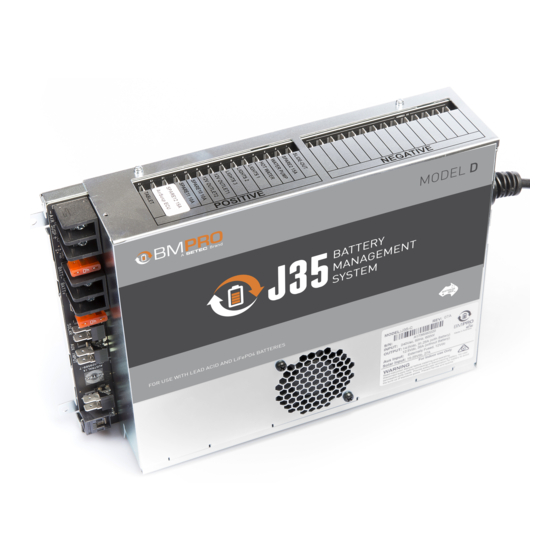
DESCRIPTION OF PARTS Figure 1: The J35 MAINS CABLE The J35 is pre-cabled with a permanent mains power supply cord. The AC mains input is protected by a quick acting, high breaking capacity type fuse (rated 250V, 10A). LOAD TERMINAL BLOCK – COMMON NEGATIVE CONNECTION Negative wire connection point for the caravan’s 12V loads. - Page 11 13-AirSusp ECU 7-Lights 3 14-Tablet Table 4: J35B-L and J35D designated terminal-load outputs for the load terminal block-positive connection Each output is protected by an internal, electronic, auto-recoverable fuse. This eliminates the need for the user to replace a blown fuse. If an electronic fuse is activated, the LED Status Indicator on the J35 will flash a solid red.
- Page 12 40A automotive battery fuse. SOLAR INPUT (J35B-L / J35D) The J35B-L supports the use of panels up to a total of 300W and the J35D up to 450W. Input current to the solar regulator is limited to 20A (J35B-L, equivalent to 2x150W solar panels) or 27A (J35D, equivalent to 3x150W solar panels).
- Page 13 When charging, Storage Mode ensures that all available charging current is dedicated to charging your battery. CAN BUS COMMUNICATION To connect to and power BMPRO accessories, such as the ControlNode or BC300 + CommLink.
-
Page 14: Controlnode
CONTROLNODE Figure 2: The ControlNode PAIRING BUTTON Button to enable Bluetooth pairing between the ControlNode and the JHub App on your own personal mobile device or JHub Tablet. LED STATUS INDICATOR Indicates the operational/pairing status of the ControlNode. Operational Status Flashing Status Note ControlNode is ready to pair Green Flash 30 sec... -
Page 15: Installation Instructions
INSTALLATION INSTRUCTIONS MOUNTING THE J35 The J35 should be securely mounted to a suitably rigid surface, using four pre- drilled mounting holes. The preferred orientation is with the load connection at the bottom.It is recommended the mounting holes are located so that there is a minimum of 80mm free air space from all vented sides of J35. -
Page 16: Connecting A Battery To The J35
CONNECTING A BATTERY TO THE J35 WARNING Sparks have the potential to cause an explosion should combustible gases be present. The following procedures are designed to minimise the risk of spark generation when connecting or disconnecting the battery. The positive terminal of the battery must not be connected to the chassis. -
Page 17: Disconnecting A Battery From The J35
WARNING Do not install a battery in the same compartment where flammable material, such as petrol, is stored. Figure 3: Connecting a house battery to the J35 After fitting a new battery to the J35, make sure that it is configured in the JHub App. -
Page 18: Connecting Multiple Batteries
CONNECTING MULTIPLE BATTERIES Before connecting multiple batteries in parallel to the J35, check that all batteries are: 9 Of the same type, for example, deep cycle AGM battery. 9 Of the same capacity, for example, 100Ah. 9 By the same manufacturer. ... -
Page 19: Using Your J35
Battery Charging The J35 can simultaneously deliver up to 20A (J35A) or 35A (J35B-L, J35D) to the caravan battery and loads from the mains input source, with a maximum charging current of 15A (J35A) or 30A (J35B-L, J35D). -
Page 20: Sleep Mode
LVD MODE LEAD ACID LiFePO4 (J35B-L and J35D ONLY) Sleep Mode 10.8V 12.0V Storage Mode 10.5V 11.5V Table 6: LVD Mode voltage thresholds The J35 will enter the two stages of LVD, Sleep Mode and Storage Mode, when the caravan’s battery voltage falls below the LVD thresholds. -
Page 21: Using The J35 As A Power Supply
The J35B-L and J35D can recover and charge a heavily discharged LiFePO4 battery. The internal Battery Management System (BMS) of a LiFePO4 battery will turn off if it detects that the battery is heavily discharged. The J35B-L or J35D will provide the voltage to restart the LiFePO4 battery’s BMS and then commence charging of the LiFePO4 battery. -
Page 22: Pairing With The Controlnode
PAIRING WITH THE CONTROLNODE To pair the ControlNode to your own personal mobile device: Make sure that the ControlNode is connected to the J35 and that the J35 is powered on. Turn on Bluetooth on your own personal device Press the Pairing Button on the ControlNode. The LED Status Indicator on the ControlNode will flash green, indicating you have 30 seconds to pair to the ControlNode. -
Page 23: Servicing, Maintenance And Storage
SERVICING, MAINTENANCE AND STORAGE SERVICING The J35 and ControlNode contain hazardous voltages and energy hazards that may cause death or injury. Only qualified service personnel may service the J35 or ControlNode. Except where stated in the following sections, do not attempt to service the J35 or ControlNode yourself, OR dismantle, modify or repair the J35 or ControlNode yourself;... -
Page 24: Faqs And Troubleshooting
App. If you would like to know more about the features of the JHub App, download the JHub Tablet Owner’s Manual from the teambmpro website. BATTERY I’ve fitted a battery to the J35, but it’s not detected by my BMPRO battery monitor? Check the following: 9 The battery connections are tight and not loose or corroded. - Page 25 None of my loads appear to be powered and the screen on my battery monitor has turned off? All loads, including any battery monitor in use with the J35 will power down if the J35 was put into Storage Mode. The J35 will be put into Storage Mode if: J35 Load Isolation input has been activated.
-
Page 26: Controlnode
CONTROLNODE How do I clear the memory of my ControlNode? To clear the ControlNode memory, press and hold the pairing button on the side of the ControlNode for 10 seconds. While the memory is being cleared, the ControlNode LED Status Indicator will flash red. -
Page 27: Appendices
AC, Charging Normally On, Solid AC, Low Battery Voltage Flashes, 1 Time AC Connected, No Battery Flashes, 1 Time (J35B-L and J35D only) Solar, Charging Normally Flashes, 2 Times Quickly Aux, Charging Normally Flashes, 3 Times Quickly AC, Battery OK or No... -
Page 28: Battery Charging Management Algorithm
BATTERY CHARGING MANAGEMENT ALGORITHM The following describes the Battery Charging Management Algorithm used by the J35 when charging the caravan battery from a mains power source. The J35 will operate as described when the caravan loads are connected directly to the J35 and not the caravan battery. -
Page 29: Charging Modes
Charging current is maintained at 10A until the battery voltage reaches 12V or soft start timeout (see table 7) occurs. Boost Mode (J35B-L and J35D) During Boost Mode, current is boosted to 30A to bring the battery voltage up to 14V, after which charging proceeds to Bulk Mode. -
Page 30: Specifications
SPECIFICATIONS J35 BATTERY MANAGEMENT J35A J35B-L J35D SYSTEM Input Voltage Range 240 VAC ± 10% (nominal), 50-60 Hz Input Surge < 40A (cold start) Output Current (Load + Battery Current) Factory Set Voltage (Float Voltage) 13.65 V +/0.1 V Output Ripple Voltage <... -
Page 31: Warranty Terms And Conditions
5. BMPRO may seek reimbursement of any costs incurred by BMPRO when a product is found to be in proper working order or damaged as a result of one or more of the warranty exclusions mentioned in point 4 of this statement. - Page 32 BMPRO TEAM sales@teambmpro.com BMPRO 19 Henderson Rd, Knoxfield VIC 3180 Australia .COM teambmpro.com...
Need help?
Do you have a question about the J35B-L and is the answer not in the manual?
Questions and answers