Table of Contents
Advertisement
Quick Links
Advertisement
Table of Contents

Related Manuals for BMPRO SwayControl


Summary of Contents for BMPRO SwayControl
- Page 1 OWNER’S MANUAL SwayControl TEAMBMPRO.COM...
- Page 2 REV 1.0 DISCLAIMER BMPRO accepts no liability for any loss or damage which may occur from the improper or unsafe use of its products. Warranty is only valid if the unit has not been modified or misused by the customer.
- Page 3 To learn more about the BMPRO range of products, please visit our website teambmpro.com team bmpro .com...
-
Page 4: About The Swaycontrol
9 Status Light Module 9 SwayControl Owner’s Manual SwayControl loom is available as an option – please contact BMPRO for pricing. COMPATIBLE BRAKE CONTROLLERS The SwayControl may be used with various integrated and aftermarket brake controllers, including brake controllers from: 9 Ford ... -
Page 5: Table Of Contents
Contents ABOUT THE SWAYCONTROL .........4 WHAT’S INCLUDED .........4 COMPATIBLE BRAKE CONTROLLERS .........4 INSTALLATION INSTRUCTIONS .........6 PERSONNEL .........6 MOUNTING LOCATION CONSIDERATIONS .........6 ORIENTATION .........6 MOUNTING .........7 WIRING INSTRUCTIONS .........9 SWAYCONTROL WIRING HARNESS .........9 WIRING DIAGRAMS ........10 Trailer Battery ........10 Ground Connections ........10... -
Page 6: Installation Instructions
To operate correctly, the SwayControl must be securely fastened onto a vertical surface of a steel trailer. Do not fasten the SwayControl to any other trailer surface that flexes or moves from wind such as plastic covers or plastic walls. -
Page 7: Mounting
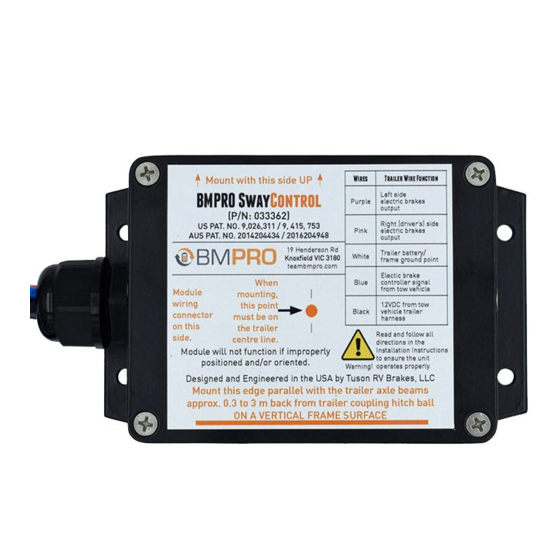
Use four #10 self-tapping screws (not supplied) with star lock washers to mount the SwayControl. It is recommended that star lock washers are used and that mounting bolts are securely tightened to hold the SwayControl firmly in position and to avoid becoming loose from vibration. WARNING DO NOT drill holes in the SwayControl for any reason. - Page 8 Figure 2: Guidance for correct mounting of SwayControl to the trailer. Table 1: SwayControl wire harness electrical connections and required wire gauge. SwayControl Required Wire Trailer Wire Function Wire Size (Minimum) PURPLE Left side electric brake output (all left side brakes) 1.8mm2...
-
Page 9: Wiring Instructions
Wiring Instructions SWAYCONTROL WIRING HARNESS The SwayControl wire harness has five wires requiring electrical connection (table 1) and one cable for the status LED light. When making connections to the caravan/trailer’s wiring harness, the desired termination is a solder joint. If the connection is not soldered, use the appropriate size and type of “crimp-type”... -
Page 10: Wiring Diagrams
50Ahr. Figure 3: Trailer Battery Wiring Ground Connections The caravan/trailer battery ground, the SwayControl ground and the electric brake ground wires must all be securely connected a 1.8 mm2 (minimum) wire in order for the SwayControl to function properly. These must be all fully grounded to a common point on the caravan/trailer. -
Page 11: 12 Volt Connections
Electric Brake (Blue Wire) Connections The tow vehicle brake signal (blue) wire must be securely connected to the SwayControl brake signal (BLUE) wire as well as to the “cold” wire from the breakaway switch. Figure 6: Electric Brake Connections Wiring... -
Page 12: Left And Right Side Brake Wires
Left and Right Side Brake Wires The SwayControl operates the left and right side trailer brakes independently in order to control caravan/trailer sway. Therefore, it is very important the correct SwayControl wires are connected to the correct side of the brakes. -
Page 13: Trailer Wiring Overview
Caravan/Trailer Wiring Overview The wiring diagram in figure 8 shows the SwayControl installed in a in a caravan/trailer. Figure 8: Wire connection to trailer plug and system overview. -
Page 14: Status Light Module Installation
Figure 9:Troubleshooting with the Status Light If the SwayControl detects a fault in the system, the Status Light will turn and the fault may be diagnosed from the Status Light flash sequence. The SwayControl... -
Page 15: Final Brake Wiring Check And Start Up
After performing the final brake wiring check, the SwayControl is ready for start-up. The operational status of the SwayControl is indicated by the LED Status Light. The SwayControl is in sleep mode if the LED Status Light is off (dark). The SwayControl will BLUE start-up (wake-up) when voltage is applied to the wire. -
Page 16: Servicing
Figure 10:Verifying correct installation of the left and right side brake wires. SERVICING Do not attempt to service the SwayControl yourself, OR dismantle, modify or repair the SwayControl yourself; this will void your warranty. If your SwayControl requires servicing, please consult your BMPRO dealer or visit teambmpro.com for assistance. -
Page 17: Troubleshooting With The Status Light
Troubleshooting with the Status Light Need more help troubleshooting your SwayControl? Contact our customer service team on line at https://teambmpro.com/technical-support/ or give us a call on (03) 9763 0962. Status Light Flash Condition or Fault Solution Sequence Solid GREEN pulsing Normal operation. -
Page 18: Warranty Terms And Conditions
5. BMPRO may seek reimbursement of any costs incurred by BMPRO when a product is found to be in proper working order or damaged as a result of one or more of the warranty exclusions mentioned in point 4 of this statement. - Page 20 BMPRO team +61 3 9763 0962 sales@teambmpro.com bmpro 19 Henderson Rd, Knoxfield VIC 3180 Australia .com teambmpro.com...
Need help?
Do you have a question about the SwayControl and is the answer not in the manual?
Questions and answers