Table of Contents
Advertisement
Advertisement
Table of Contents

Related Manuals for BMPRO J35 + ControlNode


Summary of Contents for BMPRO J35 + ControlNode
- Page 1 OWNER’S MANUAL ControlNode J35A J35B-L J35D FOR MODELS TEAMBMPRO.COM...
- Page 3 To learn more about the BMPRO range of products, please visit our website teambmpro.com TEAM BMPRO...
-
Page 4: Safety Precautions
SAFETY PRECAUTIONS Please read the Safety Precautions before installing or using the J35 and ControlNode. Be sure to observe all precautions without fail. Failure to observe these instructions properly may result in personal damage, or personal injury which depending on the circumstances may be serious and cause loss of life. WARNING Correct installation is the most critical factor in ensuring the safe use of the J35 and ControlNode. - Page 5 WARNING Stay away from magnetic equipment. Radiation may erase the information stored on this product causing it to become inoperative. Please note that your battery can only reach top performance level only after it has been fully charged and discharged two or three times. Electricity and water do not mix.
-
Page 6: Table Of Contents
DISCLAIMER: BMPRO accepts no liability for any loss or damage which may occur from the improper or unsafe use of its products. Warranty is only valid if the unit has not been modified Copyright ©... - Page 7 SERVICING, MAINTENANCE AND STORAGE ... . . 24 SERVICING......24 SERVICEABLE FUSES .
-
Page 8: About The J35
OPTIONAL ACCESSORIES To get the most from your J35 it may be used with the following products (sold separately) from the BMPRO range: 9 BC300 + CommLink External Shunt for integration of additional accessories and high current loads such as inverters 9 JHub or JControl battery monitors 9 MiniBoost or MiniBoostPRO DC-to-DC chargers. -
Page 9: Compatible Battery Types
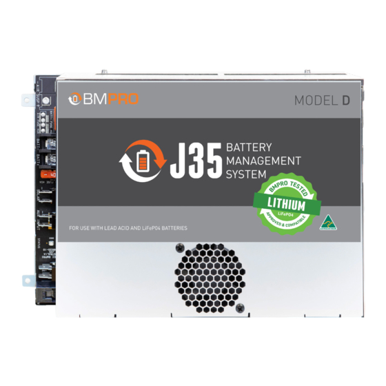
COMPATIBLE BATTERY TYPES All J35 models are compatible with lead acid batteries: 9 Valve-Regulated (VRLA) 9 Absorbed Glass Mat (AGM) 9 Gel The J35B-L and J35D are also compatible with lithium LiFePO4 batteries. By default, the J35B-L is configured to charge lead acid batteries, and the J35D is configured to charge LiFePO4 batteries. -
Page 10: Description Of Parts
DESCRIPTION OF PARTS MAINS CABLE The J35 is pre-cabled with a permanent mains power supply cord. The AC mains input is protected by a quick acting, high breaking capacity type fuse (rated 250V, 10A). LOAD TERMINAL BLOCK – COMMON NEGATIVE CONNECTION Negative wire connection point for the caravan’s 12V loads. - Page 11 Regulates the internal temperature of the J35. WARNING To ensure continuous air-flow, the fan ventilation holes must never be blocked, otherwise the temperature of the J35 may rise and inhibit the optimal operation of the J35 and/or cause the J35 to shut down. The J35 will automatically restart once it has cooled to an acceptable level.
- Page 12 When charging, Storage Mode ensures that all available charging current is dedicated to charging your battery. CAN BUS COMMUNICATION To connect to and power BMPRO accessories, such as the ControlNode or BC300 + CommLink.
-
Page 13: J35 Designated Terminal/Load Outputs
J35 DESIGNATED TERMINAL/LOAD OUTPUTS J35A Designated Terminal/Load Outputs J35A TERMINAL/LOAD CURRENT RATING 1-Stereo 2-Spare 3-Pump 4-HWS 5-Lights/Spare 6-Lights/Spare 7-Lights/Spare J35A Designated Terminal/Load Outputs J35B-L / J35D TERMINAL/LOAD CURRENT RATING 1-Slide-Out 2-Spare 2 3-Water Pump 4-Hot Water 5-Lights 1 6-Lights 2 7-Lights 3 8-12V Outlet 1 9-12V Outlet 2... -
Page 14: Controlnode
CONTROLNODE PAIRING BUTTON Button to enable Bluetooth pairing between the ControlNode and the JHub App on your own personal mobile device or JHub Tablet. LED STATUS INDICATOR Indicates the operational/pairing status of the ControlNode. For more information, refer to ControlNode LED Flash Codes. CONTROLNODE SERIAL NUMBER Required to choose the correct device when pairing the ControlNode to the JHub App on your own personal mobile device or JHub Tablet. -
Page 15: Installation Instructions
INSTALLATION INSTRUCTIONS MOUNTING THE J35 The J35 should be securely mounted to a suitably rigid surface, using four pre- drilled mounting holes. It is recommended the mounting holes are located so that there is a minimum of 80mm free air space from all vented sides of J35. This allows for the lowest operating temperature of the internal electronics and the highest reliability of the product. -
Page 16: Connecting A Battery To The J35
CONNECTING A BATTERY TO THE J35 WARNING Sparks have the potential to cause an explosion should combustible gases be present. The following procedures are designed to minimise the risk of spark generation when connecting or disconnecting the battery. The positive terminal of the battery must not be connected to the chassis. -
Page 17: Disconnecting A Battery From The J35
WARNING Before using a battery other than that which was installed at the caravan dealership, consult with the battery manufacturer for a detailed description of the installation, uses and maintenance of the battery. Verify that the type and capacity of the battery or batteries used are compatible for use with the J35. -
Page 18: Connecting Multiple Batteries
CONNECTING MULTIPLE BATTERIES Before connecting multiple batteries in parallel to the J35, check that all batteries are: 9 Of the same type, for example, deep cycle AGM battery. 9 Of the same capacity, for example, 100Ah. 9 By the same manufacturer. 9 Fully charged. -
Page 19: Using Your J35
USING YOUR J35 BATTERY CHARGING AND MANAGEMENT WITH THE J35 Input Power Sources The J35 may be powered from mains, AUX or solar inputs to provide battery charging current and power to caravan loads. If mains and one or more other sources are available to the J35, the J35 will be powered exclusively by the mains source. -
Page 20: Sleep Mode
LVD Mode Voltage Thresholds LVD MODE LEAD ACID LiFePO4 (J35B-L and J35D ONLY) Sleep Mode 10.8V 12.0V Storage Mode 10.5V 11.5V The J35 will enter the two stages of LVD, Sleep Mode and Storage Mode, when the caravan’s battery voltage falls below the LVD thresholds. SLEEP MODE When in Sleep Mode, the J35 will provide power to the CAN bus. -
Page 21: Using The J35 As A Power Supply (Batteryless Operation)
Heavily Discharged Lead Acid Batteries The J35 will not charge heavily discharged lead acid batteries. In normal use, and with the J35 battery health preservation, batteries should never become heavily discharged. If your battery is heavily discharged, disconnect it from the J35 and charge with a stand-alone charger. -
Page 22: Fault Protection
FAULT PROTECTION Overload or Short Circuit Protection If an overload or short circuit is detected the affected output will shut down. The J35 will automatically reconnect a faulty output up to 3 times within a 45-second window. If the fault is still present after the 3rd attempt, the output will be permanently disabled. -
Page 23: Pairing With The Controlnode
PAIRING WITH THE CONTROLNODE To pair the ControlNode to your own personal mobile device: Make sure that the ControlNode is connected to the J35 and that the J35 is powered on. Turn on Bluetooth on your own personal device Press the Pairing Button on the ControlNode. The LED Status Indicator on the ControlNode will flash green, indicating you have 30 seconds to pair to the ControlNode. -
Page 24: Servicing, Maintenance And Storage
SERVICING, MAINTENANCE AND STORAGE SERVICING The J35 and ControlNode contain hazardous voltages and energy hazards that may cause death or injury. Only qualified service personnel may service the J35 or ControlNode. Except where stated in the following sections, do not attempt to service the J35 or ControlNode yourself, OR dismantle, modify or repair the J35 or ControlNode yourself;... -
Page 25: Faqs And Troubleshooting
App. If you would like to know more about the features of the JHub App, download the JHub Tablet Owner’s Manual from the teambmpro website. BATTERY I’ve fitted a battery to the J35, but it’s not detected by my BMPRO battery monitor? Check the following: 9 The battery connections are tight and not loose or corroded. - Page 26 None of my loads appear to be powered and the screen on my battery monitor has turned off? All loads, including any battery monitor in use with the J35 will power down if the J35 was put into Storage Mode. The J35 will be put into Storage Mode if: The switch connected to the J35 Load Isolation input has been activated.
-
Page 27: Controlnode
CONTROLNODE How do I clear the memory of my ControlNode? To clear the ControlNode memory, press and hold the pairing button on the side of the ControlNode for 10 seconds. While the memory is being cleared, the ControlNode LED Status Indicator will flash red. -
Page 28: Appendices
APPENDICES J35 OPERATIONAL STATUS INDICATOR The following details the operational status of the J35, as shown by the coloured flash of the LED Status Indicator on the J35. STATUS COLOUR CODE FLASHING STATUS Internal Error On, Solid Identify Device Flashes, 5 Times Quickly Storage Mode Flashes Every 2min AC, Charging Normally... -
Page 29: Battery Charging Management Algorithm
BATTERY CHARGING MANAGEMENT ALGORITHM The following describes the Battery Charging Management Algorithm used by the J35 when charging the caravan battery from a mains power source. The J35 will operate as described when the caravan loads are connected directly to the J35 and not the caravan battery. -
Page 30: Charging Modes
VOLTAGE LIMIT VOLTAGE LIMIT CHARGE MODE CURRENT LIMIT (LEAD ACID) (LiFePO4) Soft Start 12.0V 12.0V Boost (J35B-L and 14.0V 14.0V J35D only) Bulk 14.4V 14.6V Absorption 14.4V 14.6V Float 13.6V 13.6V The J35’s intelligently-controlled charging algorithm automatically sets charging parameters so that the caravan battery will maintain the best state of health. -
Page 32: Specifications
SPECIFICATIONS SPECIFICATION J35A J35B-L J35D Input Voltage Range 240 VAC ± 10% (nominal), 50-60 Hz Input Surge <40A (cold start) Output Current (Load + Battery Current) Factory Set Voltage (Float Voltage) 13.65 V +/0.1 V Output Ripple Voltage <150 mV Overvoltage Protection <18V Overcurrent Protection (Load + Battery Current) -
Page 34: Warranty Terms And Conditions
The warranty period of the product is two years. If, before the warranty period has ended, a fault occurs with the product and BMPRO finds the product is defective in materials or workmanship, BMPRO at its discretion will subject to further rights accorded by the Australian Consumer Law to either: •... - Page 35 (k) the fault is a result of common wear & tear. LIMITATIONS No express warranties or representations are made by BMPRO other than what is set out in this warranty. The absolute limit of BMPRO’s liability under this express warranty is the repair or replacement of the product or part of the product.
- Page 36 BMPRO TEAM customerservice@teambmpro.com BMPRO 19 Henderson Rd, Knoxfield VIC 3180 Australia .COM teambmpro.com...
Need help?
Do you have a question about the J35 + ControlNode and is the answer not in the manual?
Questions and answers