Table of Contents
Advertisement
Quick Links
This user's guide describes the characteristics, operation, and use of the Precision Signal Injector
evaluation module (PSIEVM). The EVM facilitates the evaluation of single-ended, differential, and high-
voltage SAR analog-to-digital converters (ADC) by generating a very low distortion, low-noise signal. This
signal generator is powered by and controlled by the USB port. This user's guide provides a description of
how to configure and control the hardware using the provided software GUI.
The following related documents are available through the Texas Instruments web site at www.ti.com.
SBAU289 – October 2017
Submit Documentation Feedback
Precision Signal Injector EVM (PSIEVM)
Table 1. Associated Devices
Device
ADS8900BEVM-PDK
ADS8881EVM-PDK
ADS8681EVM-PDK
DAC8411
MSP430F5503
OPA1612
OPA1662
OPA227
OPA827
PCM5142
THS4131
Copyright © 2017, Texas Instruments Incorporated
Literature Number
SBAU269
SBAU281
SBAU252
SBAS439
SLAS645
SBOS450
SBOS489
SBOS110
SBOS376
SLAS759
SLOS318
Precision Signal Injector EVM (PSIEVM)
User's Guide
SBAU289 – October 2017
1
Advertisement
Table of Contents

Related Manuals for Texas Instruments PSIEVM


Summary of Contents for Texas Instruments PSIEVM
- Page 1 This user's guide describes the characteristics, operation, and use of the Precision Signal Injector evaluation module (PSIEVM). The EVM facilitates the evaluation of single-ended, differential, and high- voltage SAR analog-to-digital converters (ADC) by generating a very low distortion, low-noise signal. This signal generator is powered by and controlled by the USB port.
-
Page 2: Table Of Contents
Contents ........................Overview ......................PSIEVM Initial Setup ......................PSIEVM Operation ............Examples Using PSIEVM to Drive TI Data Converter EVMs ....................PSIEVM Design Overview ......................Optional Features ...................... Other Considerations ................. Bill of Materials, PCB Layout, and Schematics List of Figures ................... - Page 3 All other trademarks are the property of their respective owners. Overview The Precision Signal Injector Evaluation Module (PSIEVM, or PSI for short) is a platform for testing and evaluating the performance of successive approximation register (SAR) ADCs. The board is strictly designed to provide a low distortion, low-noise, 2-kHz input signal for driving the input of the ADC and pairs with most of TI’s SAR ADC evaluation modules (EVMs).
-
Page 4: Psievm Initial Setup
ADS8900BEVM-PDK Precision Signal Injector (PSI) GUI Installer from the Tools and Software folder of the PSIEVM and run the GUI installer to install the EVM GUI software on the user’s computer. NOTE: Manually disable any antivirus software running on the computer before downloading the EVM GUI installer onto the local hard disk. -
Page 5: Psievm Software Installation Prompts
NOTE: A notice may appear on the screen stating that Windows cannot verify the publisher of this driver software. Select Install this driver software anyway. Figure 3. Device Driver Installation Wizard Prompts The PSIEVM requires LabVIEW™ Run-Time Engine and may prompt for the installation of this software, if not already installed. SBAU289 – October 2017... -
Page 6: Labview™ Run-Time Engine Installation
PSIEVM Initial Setup www.ti.com Figure 4. LabVIEW™ Run-Time Engine Installation After these installations, verify that C:\Program Files (x86)\Texas Instruments\Precision Signal Injector is as shown in Figure Precision Signal Injector EVM (PSIEVM) SBAU289 – October 2017 Submit Documentation Feedback Copyright © 2017, Texas Instruments Incorporated... -
Page 7: Psievm Operation
LED D3 lights up indicating that the PSIEVM is powered up. 2. Launch the Precision Signal Injector GUI (PSI GUI) software. 3. Connect the PSIEVM to the desired DUT to connector P2 for single ended, or P4 and P5 for differential signal (see Table 3). -
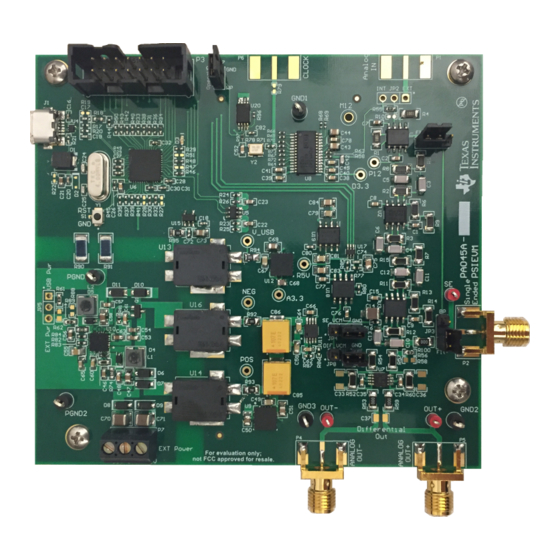
Page 8: Psievm Hardware With Labels
PSI GUI as it appears on the user’s computer screen. PSI GUI Operation: 1. Select either Single Ended or Differential to ensure the output from the PSIEVM is the type the DUT takes as an input. The plot on the GUI adjusts to match the output signal. -
Page 9: Psi Gui With Labels
Output Type Selection Figure 7. PSI GUI With Labels Setting the Offset Voltage or Common-Mode Voltage An offset voltage can be added to the single-ended output of the PSIEVM or a common-mode voltage can be added to the differential outputs. Table 4 shows the jumper combinations that are required to implement an offset or common-mode voltage. -
Page 10: Offset Voltage Example
Output Plot Amplitude 1.0-V Common Mode Voltage 2 kHz Output Enabled Jumper Explanation AC Mode Differential Output Figure 9. Common-Mode Voltage Example Precision Signal Injector EVM (PSIEVM) SBAU289 – October 2017 Submit Documentation Feedback Copyright © 2017, Texas Instruments Incorporated... -
Page 11: Examples Using Psievm To Drive Ti Data Converter Evms
PSIEVM Operation www.ti.com AC versus DC Output The PSIEVM is able to output a sine wave or a DC level. This change is made with the drop-down menu for Output Mode. Amplitude Setting and Output Enable The amplitudes selectable in the PSI GUI are available for AC single ended or differential as well as for... -
Page 12: Ads8881Evm Connected To Psievm
Examples Using PSIEVM to Drive TI Data Converter EVMs www.ti.com Table 7. Example 1 Hardware Setup Reference Designator Position or Connection ADS8881EVM J1 PSIEVM P2 ADS8881EVM JP-2 Ground ADS8881EVM JP-3 Open PSIEVM P2 ADS8881EVM J1 PSIEVM JP1, JP3 Filter PSIEVM JP4... -
Page 13: Psi Gui Setup For Ads8881Evm
Examples Using PSIEVM to Drive TI Data Converter EVMs www.ti.com Figure 11. PSI GUI Setup for ADS8881EVM SBAU289 – October 2017 Precision Signal Injector EVM (PSIEVM) Submit Documentation Feedback Copyright © 2017, Texas Instruments Incorporated... -
Page 14: Ads8881Evm Gui Spectral Analysis For Psievm Input
Examples Using PSIEVM to Drive TI Data Converter EVMs www.ti.com Figure 12. ADS8881EVM GUI Spectral Analysis for PSIEVM Input Table 9. Example 1 Results Measurement Value 97.7 dB –116.2 dB Precision Signal Injector EVM (PSIEVM) SBAU289 – October 2017 Submit Documentation Feedback... -
Page 15: Ads8900Bevm Connected To Psievm
ADC to acquire the PSIEVM output signals. Then, connect the PSIEVM to the ADS8900BEVM by having P4 and P5 on the PSIEVM attached to J7 and J3, respectively, on the ADS8900BEVM, using equal length cables, as shown in... -
Page 16: Psi Gui Setup For Ads8900Bevm
Examples Using PSIEVM to Drive TI Data Converter EVMs www.ti.com Figure 14. PSI GUI Setup for ADS8900BEVM Precision Signal Injector EVM (PSIEVM) SBAU289 – October 2017 Submit Documentation Feedback Copyright © 2017, Texas Instruments Incorporated... -
Page 17: Ads8900Bevm Gui Spectral Analysis For Psievm Input
Examples Using PSIEVM to Drive TI Data Converter EVMs www.ti.com Figure 15. ADS8900BEVM GUI Spectral Analysis for PSIEVM Input Table 12. Example 2 Results Measurement Value 100.8 dB –123.5 dB SBAU289 – October 2017 Precision Signal Injector EVM (PSIEVM) Submit Documentation Feedback... -
Page 18: Ads8681Evm Connected To The Psievm
ADS8681EVM follows. First, download the ADS8681EVM GUI to use the ADC to acquire the PSIEVM output signals. Then, connect the PSIEVM to the ADS8681EVM by having P2 on the PSIEVM attached to J1 on the ADS8681EVM as shown in Table 13 Figure 16. -
Page 19: Psi Gui Setup For Ads8681Evm
Examples Using PSIEVM to Drive TI Data Converter EVMs www.ti.com Table 14. ADS8681EVM Example Parameters Parameter Value ADS8681EVM input type Single ended PSI GUI output type Single ended ADS8681EVM maximum input range –3 × VREF to 3 × VREF = –12 V to 12 V PSI GUI amplitude 11.88 Vpp (maximum setting) -
Page 20: Psievm Design Overview
PSIEVM Design Overview www.ti.com Figure 18. ADS8681EVM GUI Spectral Analysis for PSIEVM Input Table 15. Example 3 Results Measurement Value 86.4 dB –109.6 dB PSIEVM Design Overview Analog Interface The evaluation board uses a variety of amplifiers in different configurations to compose the output signal based on the user inputs through the GUI. -
Page 21: Signal Path Illustration
Connectors for Signal Output The PSIEVM is designed to be easily interfaced with a TI SAR ADC EVM via a subminiature version A (SMA) connector. P2, P4, and P5 are SMA connectors that allow analog output connectivity through coaxial cables. -
Page 22: Optional Features
Ensure the connected power supply is at a maximum of 15 V. Fluctuating above 15 V could result in component damage. The PSIEVM must still be connected to the computer via the USB cable but this is only used for data from the GUI and not power. -
Page 23: Other Considerations
Note that by adding output resistance, there will be a voltage divider from the output resistance of the PSI and the input resistance of the DUT. The PSIEVM is fully calibrated with R53, R59, and R100 as 0-Ω resistors. Cable Selection It is best practice to minimize the length of the cabling used between the PSI and the DUT. -
Page 24: Bill Of Materials, Pcb Layout, And Schematics
Bill of Materials, PCB Layout, and Schematics www.ti.com Bill of Materials, PCB Layout, and Schematics This section contains the PSIEVM bill of materials, PCB layout, and the EVM schematics. Bill of Materials Table 17. PSIEVM Bill of Materials Item #... - Page 25 Bill of Materials, PCB Layout, and Schematics www.ti.com Table 17. PSIEVM Bill of Materials (continued) Item # Designator Quantity Value Part Number Manufacturer Description Package Reference 5.42V DDZ5V6ASF-7 Diodes Inc. Diode, Zener, 5.42 V, 500 mW, SOD-323F SOD-323F Green LG L29K-G2J1-24-Z...
- Page 26 Bill of Materials, PCB Layout, and Schematics www.ti.com Table 17. PSIEVM Bill of Materials (continued) Item # Designator Quantity Value Part Number Manufacturer Description Package Reference 1.1Meg CRCW04021M10JNED Vishay-Dale RES, 1.1 M, 5%, 0.063 W, 0402 0402 R52, R54, R57, R60...
- Page 27 Bill of Materials, PCB Layout, and Schematics www.ti.com Table 17. PSIEVM Bill of Materials (continued) Item # Designator Quantity Value Part Number Manufacturer Description Package Reference TLV70433DBVR Texas Instruments Single Output LDO, 150 mA, Fixed 3.3 V Output, 2.5 to 24 V Input, with DBV0005A Ultra-Low IQ, 5-pin SOT-23 (DBV), -40 to 125 degC, Green (RoHS &...
-
Page 28: Pcb Layer 1: Top Layer
Bill of Materials, PCB Layout, and Schematics www.ti.com PCB Layers Figure 21 through Figure 25 illustrate the EVM PCB layout. Figure 21. PCB Layer 1: Top Layer Precision Signal Injector EVM (PSIEVM) SBAU289 – October 2017 Submit Documentation Feedback Copyright © 2017, Texas Instruments Incorporated... -
Page 29: Pcb Layer 2: Ground Layer
Bill of Materials, PCB Layout, and Schematics www.ti.com Figure 22. PCB Layer 2: Ground Layer SBAU289 – October 2017 Precision Signal Injector EVM (PSIEVM) Submit Documentation Feedback Copyright © 2017, Texas Instruments Incorporated... -
Page 30: Pcb Layer 3: Power Layer
Bill of Materials, PCB Layout, and Schematics www.ti.com Figure 23. PCB Layer 3: Power Layer Precision Signal Injector EVM (PSIEVM) SBAU289 – October 2017 Submit Documentation Feedback Copyright © 2017, Texas Instruments Incorporated... -
Page 31: Pcb Layer 4: Bottom Layer
Bill of Materials, PCB Layout, and Schematics www.ti.com Figure 24. PCB Layer 4: Bottom Layer SBAU289 – October 2017 Precision Signal Injector EVM (PSIEVM) Submit Documentation Feedback Copyright © 2017, Texas Instruments Incorporated... -
Page 32: Pcb: Top Silk Screen
Bill of Materials, PCB Layout, and Schematics www.ti.com Figure 25. PCB: Top Silk Screen Precision Signal Injector EVM (PSIEVM) SBAU289 – October 2017 Submit Documentation Feedback Copyright © 2017, Texas Instruments Incorporated... - Page 33 CKT GND IN_M 100µF TLV70433DBVR CKT GND PS GND CKT GND PGND Copyright © 2017, Texas Instruments Incorporated Figure 26. Schematic Page 1 SBAU289 – October 2017 Precision Signal Injector EVM (PSIEVM) Submit Documentation Feedback Copyright © 2017, Texas Instruments Incorporated...
- Page 34 2.05k 0.1µF OUTPUT_SE_P 80.6 10µF 0.1µF VM_12 VM_12 10.0k V_CM SE_VCM Copyright © 2017, Texas Instruments Incorporated Figure 27. Schematic Page 2 Precision Signal Injector EVM (PSIEVM) SBAU289 – October 2017 Submit Documentation Feedback Copyright © 2017, Texas Instruments Incorporated...
-
Page 35: Schematic
DVCC1 DVSS1 V_MSP_3.3 10.0k V_MSP_3.3 DVCC2 DVSS2 MSP430F5503IRGZT 0.1µF 0.1µF 0.1µF Copyright © 2017, Texas Instruments Incorporated Figure 28. Schematic Page 3 SBAU289 – October 2017 Precision Signal Injector EVM (PSIEVM) Submit Documentation Feedback Copyright © 2017, Texas Instruments Incorporated... -
Page 36: Schematic
U19A Vref_DAC VOUT TRIM/NR 10µF TEMP 1µF 10µF 0.1µF REF5050AID 0.1µF Copyright © 2017, Texas Instruments Incorporated Figure 29. Schematic Page 4 Precision Signal Injector EVM (PSIEVM) SBAU289 – October 2017 Submit Documentation Feedback Copyright © 2017, Texas Instruments Incorporated... -
Page 37: Schematic
AGND 10.0k R73 PCM5142PWR DV_3.3 DV_3.3 0.1µF 10.0k 10.0k PCM_SCL PCM_SDA Copyright © 2017, Texas Instruments Incorporated Figure 30. Schematic Page 5 SBAU289 – October 2017 Precision Signal Injector EVM (PSIEVM) Submit Documentation Feedback Copyright © 2017, Texas Instruments Incorporated... - Page 38 OUT- 0.1µF THS4131IDGNR Dif_VCM V_CM 10µF 0.1µF OUTPUT_SE_P OUT+ V_12 1000pF Copyright © 2017, Texas Instruments Incorporated Figure 31. Schematic Page 6 Precision Signal Injector EVM (PSIEVM) SBAU289 – October 2017 Submit Documentation Feedback Copyright © 2017, Texas Instruments Incorporated...
- Page 39 These assemblies must be clean and free from flux and all contaminants. Use of no clean flux is not acceptable. Assembly Note These assemblies must comply with workmanship standards IPC-A-610 Class 2, unless otherwise specified. Copyright © 2017, Texas Instruments Incorporated Figure 32. Schematic Page 7 SBAU289 – October 2017...
- Page 40 STANDARD TERMS FOR EVALUATION MODULES Delivery: TI delivers TI evaluation boards, kits, or modules, including any accompanying demonstration software, components, and/or documentation which may be provided together or separately (collectively, an “EVM” or “EVMs”) to the User (“User”) in accordance with the terms set forth herein.
- Page 41 FCC Interference Statement for Class B EVM devices NOTE: This equipment has been tested and found to comply with the limits for a Class B digital device, pursuant to part 15 of the FCC Rules. These limits are designed to provide reasonable protection against harmful interference in a residential installation.
- Page 42 【無線電波を送信する製品の開発キットをお使いになる際の注意事項】 開発キットの中には技術基準適合証明を受けて いないものがあります。 技術適合証明を受けていないもののご使用に際しては、電波法遵守のため、以下のいずれかの 措置を取っていただく必要がありますのでご注意ください。 1. 電波法施行規則第6条第1項第1号に基づく平成18年3月28日総務省告示第173号で定められた電波暗室等の試験設備でご使用 いただく。 2. 実験局の免許を取得後ご使用いただく。 3. 技術基準適合証明を取得後ご使用いただく。 なお、本製品は、上記の「ご使用にあたっての注意」を譲渡先、移転先に通知しない限り、譲渡、移転できないものとします。 上記を遵守頂けない場合は、電波法の罰則が適用される可能性があることをご留意ください。 日本テキサス・イ ンスツルメンツ株式会社 東京都新宿区西新宿6丁目24番1号 西新宿三井ビル 3.3.3 Notice for EVMs for Power Line Communication: Please see http://www.tij.co.jp/lsds/ti_ja/general/eStore/notice_02.page 電力線搬送波通信についての開発キットをお使いになる際の注意事項については、次のところをご覧ください。http:/ /www.tij.co.jp/lsds/ti_ja/general/eStore/notice_02.page 3.4 European Union 3.4.1 For EVMs subject to EU Directive 2014/30/EU (Electromagnetic Compatibility Directive): This is a class A product intended for use in environments other than domestic environments that are connected to a low-voltage power-supply network that supplies buildings used for domestic purposes.
- Page 43 Notwithstanding the foregoing, any judgment may be enforced in any United States or foreign court, and TI may seek injunctive relief in any United States or foreign court. Mailing Address: Texas Instruments, Post Office Box 655303, Dallas, Texas 75265 Copyright © 2017, Texas Instruments Incorporated...
- Page 44 IMPORTANT NOTICE FOR TI DESIGN INFORMATION AND RESOURCES Texas Instruments Incorporated (‘TI”) technical, application or other design advice, services or information, including, but not limited to, reference designs and materials relating to evaluation modules, (collectively, “TI Resources”) are intended to assist designers who are developing applications that incorporate TI products;...
- Page 45 Mouser Electronics Authorized Distributor Click to View Pricing, Inventory, Delivery & Lifecycle Information: Texas Instruments PSIEVM...
Need help?
Do you have a question about the PSIEVM and is the answer not in the manual?
Questions and answers