Table of Contents
Advertisement
Quick Links
www.ti.com
User's Guide
AWR2944 Evaluation Module
Started........................................................................................................................................................................2
1.1 Introduction........................................................................................................................................................................
.....................................................................................................................................................................2
Included..................................................................................................................................................................2
2 Hardware.................................................................................................................................................................................
Diagram....................................................................................................................................................................5
Recommendations......................................................................................................................................5
2.3 Power Connections............................................................................................................................................................
2.4
Connectors.........................................................................................................................................................................6
2.5
Antenna............................................................................................................................................................................15
2.6 PMIC................................................................................................................................................................................
2.7 On-Board Sensors...........................................................................................................................................................
2.8 PC Connection.................................................................................................................................................................
2.10 Jumpers, Switches, and LEDs.......................................................................................................................................
3.1 Design Files.....................................................................................................................................................................
4 Revision History...................................................................................................................................................................
Trademarks
ARM
®
and Cortex
®
are registered trademarks of Arm Limited.
Windows
®
is a registered trademark of Microsoft.
All trademarks are the property of their respective owners.
SPRUJ22A - NOVEMBER 2021 - REVISED MARCH 2023
Submit Document Feedback
Table of Contents
EVM.....................................................................................................20
Tools.........................................................................................................................................26
Code..........................................................................................................26
Copyright © 2023 Texas Instruments Incorporated
Table of Contents
2
3
6
17
17
18
21
26
27
AWR2944 Evaluation Module
1
Advertisement
Table of Contents

Related Manuals for Texas Instruments AWR2944


Summary of Contents for Texas Instruments AWR2944
-
Page 1: Table Of Contents
Arm Limited. Windows ® is a registered trademark of Microsoft. All trademarks are the property of their respective owners. SPRUJ22A – NOVEMBER 2021 – REVISED MARCH 2023 AWR2944 Evaluation Module Submit Document Feedback Copyright © 2023 Texas Instruments Incorporated... -
Page 2: Getting Started
The following power supply has been tested to work with the AWR2944EVM: SDI65-12-U-P5. 1.3.2 mmWave Out-of-Box (OOB) Demo TI provides sample demo codes to easily get started with the AWR2944 evaluation module (EVM) and to experience the functionality of the AWR2944 radar sensor. For details on getting started with these demos, see www.ti.com/tool/mmwave-sdk. -
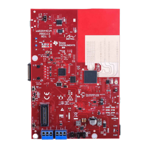
Page 3: Hardware
During operation, a minimum separation distance of 5 centimeters must be maintained between the user and the EVM. Figure 2-1. AWR2944EVM Front View SPRUJ22A – NOVEMBER 2021 – REVISED MARCH 2023 AWR2944 Evaluation Module Submit Document Feedback Copyright © 2023 Texas Instruments Incorporated... - Page 4 Hardware www.ti.com Figure 2-2. AWR2944EVM Back View AWR2944 Evaluation Module SPRUJ22A – NOVEMBER 2021 – REVISED MARCH 2023 Submit Document Feedback Copyright © 2023 Texas Instruments Incorporated...
-
Page 5: Block Diagram
EVM in the supplied ESD bag when not in use. Handle using an antistatic wristband. Operate on an antistatic work surface. For more information on proper handling, refer to SSYA010A. SPRUJ22A – NOVEMBER 2021 – REVISED MARCH 2023 AWR2944 Evaluation Module Submit Document Feedback Copyright © 2023 Texas Instruments Incorporated... -
Page 6: Power Connections
To use this interface, the JTAG lines from the AWR2944EVM needs to be muxed to MIPI 60-pin connector. Refer Section 2.8.1 for more details. AWR2944 Evaluation Module SPRUJ22A – NOVEMBER 2021 – REVISED MARCH 2023 Submit Document Feedback Copyright © 2023 Texas Instruments Incorporated... - Page 7 Description MIPI_VREF_DEBUG MIPI_TMS MIPI_TCK MIPI_TDO MIPI_TDI MIPI_NRST MIPI_RTCK MIPI_TRSTPD MIPI_JTAG_NRST MIPI_VREF_DEBUG TRACE_CLK MIPI_DBG_DETECT TRACE_CTL TRACE_DATA0 TRACE_DATA1 TRACE_DATA2 TRACE_DATA3 TRACE_DATA4 TRACE_DATA5 SPRUJ22A – NOVEMBER 2021 – REVISED MARCH 2023 AWR2944 Evaluation Module Submit Document Feedback Copyright © 2023 Texas Instruments Incorporated...
- Page 8 The SPI is multiplexed to the Debug Connector. For more details refer to Section 2.8.1. Figure 2-6. 60-pin Debug Connector AWR2944 Evaluation Module SPRUJ22A – NOVEMBER 2021 – REVISED MARCH 2023 Submit Document Feedback Copyright © 2023 Texas Instruments Incorporated...
- Page 9 GPADC7 GPADC8 GPADC9 MSS_SPIB_CS1 SOP1_MSS_SPIB_CS2 MSS_GPIO_0 MSS_GPIO_1 LVDS_TX2_CLK_P AR_WRMRST LVDS_TX2_CLK_N AR_NERROUT LVDS_TX1_P MSS_I2CA_SCL LVDS_TX1_N MSS_I2CA_SDA MSS_EPWMB0 LVDS_TX0_P MSS_EPWMA1 LVDS_TX0_N MSS_GPIO_3 SPRUJ22A – NOVEMBER 2021 – REVISED MARCH 2023 AWR2944 Evaluation Module Submit Document Feedback Copyright © 2023 Texas Instruments Incorporated...
- Page 10 CAN_B connector connector. Table 2-4. J2 Pin Assignment Pin Number Description CAN_L CAN_H AWR2944 Evaluation Module SPRUJ22A – NOVEMBER 2021 – REVISED MARCH 2023 Submit Document Feedback Copyright © 2023 Texas Instruments Incorporated...
- Page 11 MDIO Clause 22 and 45 PHY management interface • IEEE 1588 Synchronous Ethernet support The Ethernet port is interfaced to the AWR2944 through the Ethernet PHY and is used to stream the captured data over the network to the host PC. Figure 2-9...
- Page 12 15. Populate D18 and D19 ESD diodes 16. Populate C55 17. The bootstrap configuration pins can be populated/removed as needed depending on the use case AWR2944 Evaluation Module SPRUJ22A – NOVEMBER 2021 – REVISED MARCH 2023 Submit Document Feedback Copyright © 2023 Texas Instruments Incorporated...
- Page 13 USB cables, power cycle the EVM, and plug in the USB cables to resolve the issue. The AWR2944EVM has two standard micro USB connectors. Micro USB Connector J10 provides access to the AWR2944 UART, SPI, I2C, RS232, and SOP interfaces through the FTDI chip. Table 2-7. J10 Pin Assignment...
- Page 14 XDSET_ID Figure 2-12. XDS USB Port 2.4.7 OSC_CLKOUT Connector (J14) Connector J14 provides access to measure oscillator clock out signal from the AWR2944 device. Figure 2-13. OSC Clock Port AWR2944 Evaluation Module SPRUJ22A – NOVEMBER 2021 – REVISED MARCH 2023 Submit Document Feedback Copyright ©...
-
Page 15: Antenna
2.4.9 Voltage Rails Ripple Measurement Connectors (J1, J5) (DNP) J1 Provides access to measure ripple on 1V0_FILTERED (1.0 analog RF supply for AWR2944) voltage rail. J5 Provides access to measure ripple on 1V8_FILTERED (1.8-V analog supply for AWR2944) voltage rail. - Page 16 2-17). Similarly, the horizontal 6 dB beamwidth is approximately ±45 degrees (see Figure 2-16) and the elevation 6dB-beamwidth is approximately ±5 degrees (see Figure 2-17). Figure 2-16. Azimuth Radiation Pattern AWR2944 Evaluation Module SPRUJ22A – NOVEMBER 2021 – REVISED MARCH 2023 Submit Document Feedback Copyright © 2023 Texas Instruments Incorporated...
-
Page 17: Pmic
Hardware Figure 2-17. Elevation Radiation Pattern 2.6 PMIC Power to the AWR2944 is provided by the LP877451-Q1 PMIC. This is a functional safety compliant PMIC that supports ASIL-C/SIL-2 applications. For more details, visit the LP87745-Q1 product page (https://www.ti.com/ product/LP87745-Q1). -
Page 18: Pc Connection
Ports (COM & LPT). Figure 2-18. XDS110 COM Ports XDS110 debug probe and data port are detected under Texas Instruments Debug Probes. Figure 2-19. TI Debug Probes If the PC is unable to recognize the above COM ports, install the latest EMUpack. - Page 19 COM ports are installed, the device manager recognizes these devices and indicates the COM port numbers, as shown in Figure 2-21. Figure 2-21. Installed FTDI Drivers SPRUJ22A – NOVEMBER 2021 – REVISED MARCH 2023 AWR2944 Evaluation Module Submit Document Feedback Copyright © 2023 Texas Instruments Incorporated...
-
Page 20: Connecting The Awr2944Evm To The Dca1000 Evm
When using the AWR2944EVM with the DCA1000 EVM, the following settings must be used. 1. Set the AWR2944EVM to SOP2 mode. Figure 2-23. SOP2 Mode AWR2944 Evaluation Module SPRUJ22A – NOVEMBER 2021 – REVISED MARCH 2023 Submit Document Feedback Copyright © 2023 Texas Instruments Incorporated... -
Page 21: Jumpers, Switches, And Leds
MIPI 60-pin connector (J19). When set to ‘XDS’ position, the JTAG interface is routed to the XDS110 USB interface (J8) SPRUJ22A – NOVEMBER 2021 – REVISED MARCH 2023 AWR2944 Evaluation Module Submit Document Feedback Copyright © 2023 Texas Instruments Incorporated... - Page 22 ONLY during boot up of the AWR2944 device. The state of the device is described in Table 2-12. A closed jumper refers to a ‘1’ and open the jumper refers to a ‘0’ state of the SOP signal going to the AWR2944 device. Note The SOP[2:0] pins can also be controlled via the on-board FTDI.
- Page 23 2.10.3 I2C Connections The board features temperature sensor for measuring onboard temperature, current sensors for current measurement for 1.2-V, 1.8-V, 3.3-V, 1V0_RF1, and 1V0_RF2 AWR2944 supply rails and EEPROM for storing board ID. These are connected to the AWR2944EVM through I2C bus.
- Page 24 This LED indicates the presence of 12-V supply input Green 5-V Supply This LED indicates the presence of 5-V supply output AWR2944 Evaluation Module SPRUJ22A – NOVEMBER 2021 – REVISED MARCH 2023 Submit Document Feedback Copyright © 2023 Texas Instruments Incorporated...
- Page 25 Open drain fail safe warm reset signal Green GPIO_2 Glows when the GPIO_2 is logic-1 Yellow FTDI_SUSPEND_N Glows when FTDI is in suspend state SPRUJ22A – NOVEMBER 2021 – REVISED MARCH 2023 AWR2944 Evaluation Module Submit Document Feedback Copyright © 2023 Texas Instruments Incorporated...
-
Page 26: Design Files And Software Tools
(HWA 2.0), TI provides a software development kit (SDK) that includes demo codes, software drivers, emulation packages for debug, and more. These can be found at mmwave-sdk. AWR2944 Evaluation Module SPRUJ22A – NOVEMBER 2021 – REVISED MARCH 2023 Submit Document Feedback Copyright © 2023 Texas Instruments Incorporated... -
Page 27: Revision History
• Added PMIC section............................• Changed all instances of legacy terminology to controller and target where I C is mentioned......SPRUJ22A – NOVEMBER 2021 – REVISED MARCH 2023 AWR2944 Evaluation Module Submit Document Feedback Copyright © 2023 Texas Instruments Incorporated... - Page 28 STANDARD TERMS FOR EVALUATION MODULES Delivery: TI delivers TI evaluation boards, kits, or modules, including any accompanying demonstration software, components, and/or documentation which may be provided together or separately (collectively, an “EVM” or “EVMs”) to the User (“User”) in accordance with the terms set forth herein.
- Page 29 www.ti.com Regulatory Notices: 3.1 United States 3.1.1 Notice applicable to EVMs not FCC-Approved: FCC NOTICE: This kit is designed to allow product developers to evaluate electronic components, circuitry, or software associated with the kit to determine whether to incorporate such items in a finished product and software developers to write software applications for use with the end product.
- Page 30 www.ti.com Concernant les EVMs avec antennes détachables Conformément à la réglementation d'Industrie Canada, le présent émetteur radio peut fonctionner avec une antenne d'un type et d'un gain maximal (ou inférieur) approuvé pour l'émetteur par Industrie Canada. Dans le but de réduire les risques de brouillage radioélectrique à...
- Page 31 www.ti.com EVM Use Restrictions and Warnings: 4.1 EVMS ARE NOT FOR USE IN FUNCTIONAL SAFETY AND/OR SAFETY CRITICAL EVALUATIONS, INCLUDING BUT NOT LIMITED TO EVALUATIONS OF LIFE SUPPORT APPLICATIONS. 4.2 User must read and apply the user guide and other available documentation provided by TI regarding the EVM prior to handling or using the EVM, including without limitation any warning or restriction notices.
- Page 32 Notwithstanding the foregoing, any judgment may be enforced in any United States or foreign court, and TI may seek injunctive relief in any United States or foreign court. Mailing Address: Texas Instruments, Post Office Box 655303, Dallas, Texas 75265 Copyright © 2023, Texas Instruments Incorporated...
- Page 33 TI products. TI’s provision of these resources does not expand or otherwise alter TI’s applicable warranties or warranty disclaimers for TI products. TI objects to and rejects any additional or different terms you may have proposed. IMPORTANT NOTICE Mailing Address: Texas Instruments, Post Office Box 655303, Dallas, Texas 75265 Copyright © 2023, Texas Instruments Incorporated...
Need help?
Do you have a question about the AWR2944 and is the answer not in the manual?
Questions and answers