Advertisement
Quick Links
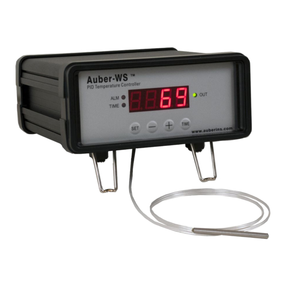
Programmable Controller for Electric Smoker
Introduction
Thank you for purchasing the Auber WS series temperature controller. We sincerely
appreciate your decision and trust that our machine will meet your expectations in both
the quality of the result and the value of our product. While we are delighted that you may
be anxious to operate the controller for your project, a few minutes of your time reading
through this manual will only serve to enhance your experience in the months and years
ahead. In particular, we urge you to read through the safety warnings below. Although
this plug-and-play controller is very easy to operate, the process involves high
temperature and high wattage appliances and your safety is paramount.
This controller is designed only to be used with devices that have limited power
and their own thermal cutoff protection, such as a thermostat or thermal fuse in
case of controller failure.
Do not place any objects on the top of controller surface which is used to vent
excess heat during its operation.
The maximum electric current this controller can handle is 13 Ampere. For 120
volt AC in US and Canada, this limits the heater power to 1600 watts. Due to its
compact size and the splash proof design for kitchen applications, the controller
has a limited ability to dissipate the heat generated by the internal solid state relay
during the initial heat up. The initial full power heat up process cannot be more
than 90 minutes. If you system need take longer time to warm up, please read
Appendix 1 "Managing the heat generated by the controller"
Operation Instruction Manual
WS-1500EPM
Version 1.3 (Dec, 2016)
Auber Instruments
5755 North Point Parkway, Suite 99
Alpharetta, GA 30022
770-569-8420
www.auberins.com
SAFETY WARNINGS
1
Advertisement

Related Manuals for Auber Instruments WS-1500EPM


Summary of Contents for Auber Instruments WS-1500EPM
- Page 1 Operation Instruction Manual WS-1500EPM Programmable Controller for Electric Smoker Version 1.3 (Dec, 2016) Auber Instruments 5755 North Point Parkway, Suite 99 Alpharetta, GA 30022 770-569-8420 www.auberins.com Introduction Thank you for purchasing the Auber WS series temperature controller. We sincerely appreciate your decision and trust that our machine will meet your expectations in both the quality of the result and the value of our product.
-
Page 2: Specifications
Instruments only. Using it to control a not recommended device can be dangerous and cause fire. Auber Instruments is not liable for damages caused by misuse of the controller. If you are not sure the controller can be used, please contact Auber Instruments before use. - Page 3 Operating Instructions 1) Description of the controller. Figure 1. Front Panel (1) Parameter Window (LED) - For displaying temperature values and controller's system parameters. (2) Output status indicator - In normal mode, this LED indicates the heater status. When it is on (lit), the heater is powered. When it is off, the heater power is off. When it is flashing, it means the heater is on and off intermittently to reduce the power output.
- Page 4 When it is flashing and “(8)” stays on, “(1)” is the time that has elapsed since it’s powered on. When it is flashing “(8)” is off, the controller is in the parameter setting mode. “(1)” is the value can be changed by using (4) and (5) key. Figure 2.
- Page 5 2) Connecting the controller There are two ways to power up the controller and smoker. a) Using two power cords and a power strip. This set up is good for the “Original”, Stainless Steel, and Digital Bradley Smoker. Figure 3. Power connection of the controller and smoker. The input of the controller is connected to the power strip by the 16 AWG power cord supplied (blue arrows).The generator is connected to the power strip by the power cord from Bradley (green arrows).
- Page 6 Fig 4. Power connection of the controller and smoker. The generator is connected to the power strip by the power cord from Bradley (green arrows). The input of the controller is connected to the female receptacle on the generator by the power jumper cord provided by the Bradley (blue arrows). It is the cord that used to connect the generator to smoker.
- Page 7 Figure 5. Sensor position. Left, the sensor should be placed close to the food but high enough so that it does not touch the food. Right, hold the sensor in place by a piece of tape. For the “Original” and Stainless Steel Bradley smoker, the Temperature Heat Control Switch on the smoker tower should be slide to the Hi position (Most right).
- Page 8 Remark The connector of sensor contains a slot for correct pin connection. It also has a spring lock to prevent disconnections from accidental pulling on the cable. The following pictures show how to install and remove it. Figure 3. How to install the sensor. Figure 4.
- Page 9 3) Programming the temperature profile. A total of 6 steps can be programmed for this controller. Each step contains the temperature (C0X) and time duration (T0X) setting. They are represented by the symbol C0X and T0X, where “X” is the step number (e.g. Step 4 temperature is represented by C04 and step 4 time is represented by T04).
- Page 10 4 sec Figure 5. Temperature profile programming flow chart. The temperature setting will not be changed if SET is not pressed (confirmed). After programming the necessary steps for cooking, you can finish programming by pressing the SET continuously until the display passes T06 and displays the current temperature. You can also leave the controller alone.
- Page 11 Table 1. Initial program setting Step # Temp (F) Step # Time (min) 4) Checking the current step and display the time This is done by pressing the Time Key “(6)” once. The display will show T0X for one second before it displays the time it has been on that step. e.g., it will display t03 for a second, if the controller is in step 3 of process.
- Page 12 Slow cooker, 7 quart Slow cooker, 4 quart Slow cooker, PD mode (low overshoot) Bradley Smoker Please note that the P value in table is in Fahrenheit unit. If the controller is using Celsius unit, divide the P value by 1.8. If you switch from Fahrenheit display to Celsius, the controller will automatically convert all the settings.
- Page 13 value was found when operating the controller in Celsius, it needs to be multiplied by 1.8 when changed to Fahrenheit. On/off mode. If P is set to 0, the control mode will be changed from PID mode to On/off mode. On/off mode should be used for controlling an external relay, a solenoid valve, or a compressor of freezer.
- Page 14 Figure 6. Auto-Tuning Before using the auto-tune function, you must set the cooking equipment up in the exact configuration it will be used. For example, to tune a rice cooker, place the sensor in the room temperature pot filled with water and plug the cooker into the controller.
- Page 15 every 10 seconds. This parameter should set at 2 second for heating with an electric heater. When controlling a solenoid valve or a compressor of refrigerator, the T should be set to 10-20 to reduce the frequency of on/off. To prevent changing critical parameters by accident, an access lock, LCK is used. Special code is needed to open the lock for these parameters.
- Page 16 and press SET will activate the auto-tune. The next setting is the “t” setting, use “-” and “+” to set the cycle time value. This value should remain 2 for most application. After change the PID parameter, the controller needs to be turned off and on again for the best result.
- Page 17 Hy. Hysteresis band (or dead band). This parameter is used for on/off control only. In the on/off heating mode, the heater will be turned off when T = SV, and turned on again when T<SV-Hy. e.g. If SV=100 ° C. Hy=3 ° C, the heater will heat until temperature reaches 100 °...
- Page 18 3 sec Cool Figure 8. Code 155 Parameter setup flow chart Press and hold SET key for 4 seconds until the Parameter Window displays “LCK”. Release the SET. The display will show “0”. Use “+” and “-” keys to adjust the display to 155 (another pass code) and press SET.
-
Page 19: Warranty
Alpharetta, GA 30022 If the appliance is found by Auber Instruments to be defective in material or workmanship, Auber Instruments will repair or replace it free of charge. A dated proof of purchase may be required. The liability of Auber Instruments is limited solely to the cost of the repair or replacement of the unit at our discretion. - Page 20 Copyright 2007-2016, Auber Instruments All Rights Reserved. No part of this manual shall be copied, reproduced, or transmitted in any way without the prior, written consent of Auber Instruments. Auber Instruments retains the exclusive rights to all information included in this document.
- Page 21 Appendix 1 Managing the heat generated by the controller The heat dissipation of the controller is directly related to the electric current drawing power of the heater. If your cooker consumes less than 10 ampere of current or your pot is less than 5 gal (19 liters), you do not need to worry about the heat generated by the controller.
- Page 22 minutes will provide enough energy to heat 10 gallons (38 liters) of water up by 108° F (60 ° C). If your have a pot that is bigger than 10 gallons and the heater is drawing 15 A, and you need to raise the temperature by 108 ° F, you better use one of the methods mentioned below to reduce the heat in the controller.
Need help?
Do you have a question about the WS-1500EPM and is the answer not in the manual?
Questions and answers