
Related Manuals for Eneo IAR-7SE1024MMC


Summary of Contents for Eneo IAR-7SE1024MMC
- Page 1 Quick Installation Guide Gigabit Switch managed, 350W, Layer 3, 24xPoE, 4x SFP Gigabit, Rack, Desktop IAR-7SE1024MMC...
- Page 2 About Documents This document is Quick Installation Guide. It is intended for engineers or anyone who needs to install the product. Announcement The information in this document is subject to change without notice. The document is only used as operation guide, except for other promises. No warranties of any kind, either express or implied are made in relation to the description, information or suggestion or any other contents of the manual.
-
Page 3: Table Of Contents
Content Packing List .................... 1 Product Introduction ................2 Overview ..................2 Hardware Introduction ..............2 2.2.1 24-Port Switch ................2 2.2.1 24-Port PoE Switch ..............4 Safety Precaution ................. 6 Insatallation Steps ................ 8 3.2.1 Rack Mount .................. 9 3.2.2 Desktop Installation .............. -
Page 4: Packing List
Packing List Open the box of the product and carefully unpack it. The box should contain the following items. Please check before installation, if any missing, please contact your dealer immediately. Items Quantity Switch 1 pc AC Power Cable 1 pc Mounting Accessory 1 set Quick Installation Guide... -
Page 5: Product Introduction
Product Introduction 2.1 Overview This series switch provide twenty-four Gigabit Ethernet RJ-45 ports and four 10G SFP uplink ports. It has extensive L3 management functions and can be easily managed via a WEB GUI (http/https), CLI (telnet/ssh/console) or SNMP. This series contains two types: ... - Page 6 Led Indicators Instructions Indicators Status Descriptions The Main Power Supply is working. Main Power Supply PWR1 Indicator The Main Power Supply is off. The Redundant Power Supply is working. Redundant Power PWR2 Supply Indicator The Redundant Power Supply is off. The port is linking normally.
-
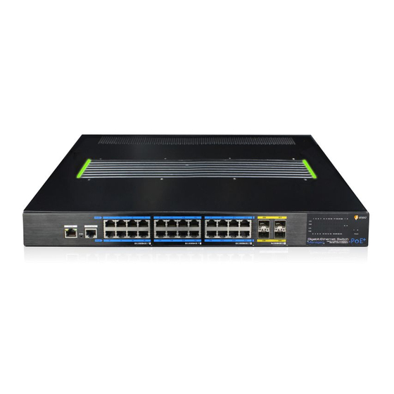
Page 7: 24-Port Poe Switch
2.2.1 24-Port PoE Switch Front Panel Rear Panel Led Indicators Instructions Indicators Status Descriptions The Main Power Supply is working. Power Supply Indicator The Main Power Supply is off. The port is linking normally. 1~24 Downlink Port Link The port is transmitting or receiving Blink Indicator data. - Page 8 Flow control mode Not support Test mode Not support Stop bits Data bits Init Button The init button has two operating modes. By short pressing the button, the switch will be reset and the configuration is as previous setting saved. ...
-
Page 9: Safety Precaution
Installations 3.1 Safety Precaution To minimize the technically residual risk, it is imperative to obey the following rules. Read all the instructions before operation. The Caution, Warning and Danger items in other documents do not cover all the safety precautions that must be followed. They are only supplementary information. When operating the device, obey the local safety regulations. - Page 10 Inflammable Environment DANGER Do not place the device in the environment that has inflammable and explosive air or fog. Do not perform any operation in this environment. Operating the electrical device in inflammable environment can be fatal. Moisture proof WARNING Water or moisture in the equipment will damage the circuit of the equipment.
-
Page 11: Insatallation Steps
3.2 Insatallation Steps This series switch supports 3 installation methods: Rack mount Desktop installation Wall mount Following with the dimensions of the switch and its insatallation accessories. The two types are of the same dimensions. Here take 24-Port PoE Switch as example. Dimensions (mm) -
Page 12: Rack Mount
3.2.1 Rack Mount This series switch supports 19” rack-mounted installtaion. Following with the installation steps. Step 1: Fix the hangers on the side of the switch. Accessories Step 2: Install the switch on the rack with screws in the Accessories package. -
Page 13: Desktop Installation
3.2.2 Desktop Installation This series switch supports desktop installation. Users can put this product on clean, stable, grounded workbench. The installation steps are as below: Carefully put the device upside down, clean the grooves on the chassis backplane with soft cloth to make sure there is no oil or dust in it. ... - Page 14 Items Specifications Power Input Input Voltage AC 100~240V 50/60Hz Input Current 2A max Power Output Output Voltage 12V DC Output Current 5A max Power Consumption 60W (full load) Connect the AC power cable to the switch through the power input interface. It is recommended to use the AC power cable provided in the package.
- Page 15 connection first and disconnect it at the end when operating the unit. Power on the system only after confirming that the wiring is correct, to avoid damage to the equipment. Read the user manual carefully before operating or maintaining the repeater to avoid misoperation.
- Page 16 Specifications Items 24-Port Switch 24-Port PoE Switch Ethernet Ports 24*10/100/1000Base-T RJ45 24*10/100/1000Base-T PoE Downlink Ports (Auto-MDI/MDI-X) RJ45 (Auto-MDI/MDI-X) Uplink Ports 4*1000M/10G Base-X SFP(Mini-GBIC) Console Port 1*RJ45-R232 serial port (115200,8,N,1) PoE Standard IEEE 802.3af/at (PSE) PoE Power Supply End-span Type PoE Pin Assignment 1/2(+), 3/6(-) PoE Power Output 46~55V DC...
- Page 17 Operating -10~50 Temperature Storage -40~75 Temperature Operating Humidity 5%~95% (Non-condensation) Physical Parameters 1*PWR Indicator 2*PWR Indicator 24*Downlink Port Link Indicator 24*Downlink Port Link Led Indicators Indicator 24*Downlink Port PoE Indicator 4*Uplink Port Link Indicator 4*Uplink Port Link Indicator Short press to restart Init Button Long press 5s to initialize the system...
- Page 19 VIDEOR E. Hartig GmbH Exclusive distribution through specialised trade channels only. VIDEOR E. Hartig GmbH Carl-Zeiss-Straße 8 63322 Rödermark/Germany Tel. +49 (0) 6074 / 888-0 Technical changes reserved Fax +49 (0) 6074 / 888-100 www.videor.com...
Need help?
Do you have a question about the IAR-7SE1024MMC and is the answer not in the manual?
Questions and answers