
Subscribe to Our Youtube Channel
Related Manuals for Eneo 221890


Summary of Contents for Eneo 221890
- Page 1 User Manual Gigabit Switch, Managed, 24xGb SFP slots, 8xGb RJ45 ports, 4x10Gb uplink SFP slots IAR-7SM1024MMB...
-
Page 2: Table Of Contents
Content Product Introduction................................4 Overview...................................4 Product Feature................................ 4 Board Diagram................................5 Specification................................6 Installation.................................... 6 Shipping List................................7 Installation Precautions............................7 Installation Way................................ 9 Cable Connection..............................11 Function Configuration Guide............................12 Computer Requirements............................12 Set Up Network Connection...........................13 Web Page Configuration Guide..........................16 Quick Guide.................................. - Page 3 Chapter 12 IP Route................................66 11.1 IP Route..................................66 11.2Routing table configuration............................67 System Management..............................69 12.1 IP Address................................69 12.2 Username and password............................71 12.3 SNMP Setup................................72 12.4 Log Output................................75 12.5 File Management..............................76 Console Interface Settings..............................77 13.1 Login Equipment Console Interface........................77...
-
Page 4: Product Introduction
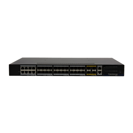
1 Product Introduction 1.1 Overview The 24 Gigabit ports managed Ethernet switch, which provide 24 Gigabit SFP slots , 8 * 10/100/1000 RJ45 combo ports , and 4* 1000/10G uplink SFP slots . The product support Web layer-3 network management . Products are widely used in security surveillance, network engineering projects and so on. -
Page 5: Board Diagram
1.3 Board Diagram... -
Page 6: Specification
1.4 Specification Products are subject to change without prior notice. 2 Installation Caution Anti-counterfeiting label is attached to switch's cover. Product damage caused by... -
Page 7: Shipping List
unauthorized disassembly is not covered under warranty. 2.1 Shipping List Please check the following items before installation, if any missing, please contact your local dealer. the 24S and 16S switch have redundance power module . 2.2 Installation Precautions To avoid device damage or personal injury by improper use, please observe the following precautions. - Page 8 failure; The switch will work normally under the correct voltage. Please ensure the voltage indicated on the switch corresponds to the power voltage; To avoid the danger of electric shock, please do not open the switch case. Do not open the switch case even if the switch is powered off;...
-
Page 9: Installation Way
high-frequency devices; Use electromagnetic shielding if necessary, such as shielded cable; Interface cables should be arranged indoor rather than outdoor to prevent over-voltage or over-current damage to the signal port. 2.3 Installation Way There are 3 installation ways: rack, workbench and wall-hung installation. Caution Please pull out the power plug before installing or moving the switch. - Page 10 (4) Use screws to fit the installation hanger at rack’s fixed slot, make sure the device is installed at rack’s bracket steadily. Instruction This product’s fixing hangers are just to fix the switch rather than support it. Use brackets under the device (fixed to the rack) to support switch when install the switch to the rack. 2.3.2 Workbench Installation You can put this product on clean, stable, grounded workbench.
-
Page 11: Cable Connection
(2) Drill holes on the strong position of wall and then drive the rubber plug into the hole; (3) Drive these screws into the hole for the rack and fix the product by aiming at the rubber plug . 2.4 Cable Connection 2.4.1 Device Connection Use cross network cable or cross-over cable to connect PC or other device with switch's Ethernet port;... -
Page 12: Function Configuration Guide
If CLS management,use a console cable to connect the Console port and the computer’serial port(DB9); as the following figure: 2.4.3 Power cable Connection (1)Connect one side of switch’s power cable with the switch's AC power port, and connect the another side with external AC power socket; (2)Turn on the power ,check if switch's AC power LED is on, that means power connected correctly;... -
Page 13: Set Up Network Connection
console port. 3.2 Set Up Network Connection Instruction (1) You need to set the IP of the PC and the switch in the same network segment. The default IP address of the switch is 192.168.1.200, network gate is 255.255.255.0. (2) The port to connect management PC for Web setting must be management VLAN. By default, management VLAN is VLAN 1,and each port of the switch is VLAN1. - Page 14 (2) Click <property> button, enter "locw. (3)Select "Internet protocol (TCP/IP), click <property> button, enter”Internet protocol (TCP/IP) property” window. Select “ use the IP address below” button, input IP address ( use arbitrary value between 192.168.1.1~192.168.1.254, besides 192.168.1.200) and the subnet mask(255.255.255.0). Click "OK" to finish the configuration. Instruction DNS server address can be empty or be filled in with the real server address.
- Page 15 3.2.2 Confirm the Network Connection by Ping Command Operation Steps below: (1) Click <Start> button to enter [Start] menu, select [Run], pop out the dialog. (2) Input "ping 192.168.1.200", click <confirm> button. If there is equipment response show in the pop out dialog, that means network connection succeed, otherwise please check if the network connection is correct.
-
Page 16: Web Page Configuration Guide
(2) Select “connection” tabs in [Internet option] window, and click [LAN Setting] button. (3) Make sure the “Use proxy server for LAN”option is not selected. If selected, please cancel it and click <yes> button. The menu bar has the following options: [System Status], [Port Configuration], [VLAN Settings], [QoS management], [link management], [Port Security], [network management], [Network Statistics], [System management], [Exit] and drop-down menu bar of the "language switching function". - Page 17 and later). 3.3.1 Start and Login This product web default IP address: 192.168.1.200, subnet mask: 255.255.255.0, administrator account: admin, password: admin. After installing the equipment correctly and setting up the computer, open the browser, input the switch default address in the browser address bar: http://192.168.1.200, then press the Enter key, the user login page will show in front of you as follows: Caution...
- Page 18 By default, the management VLAN is VLAN 1, same as each port of switch. After inputting the correct password, click <Login in>, the browser will display the product Web management page as the picture below: W eb man age men t pag e diagra m 3.3.2 Change Language As shown below, in the upper right corner of the Web page, click on the drop-down menu bar, select [Chinese] or [English], to complete Web language switching.
-
Page 19: Quick Guide
4 Quick Guide 4.1 Quick Guide 4.1.1 Port VLAN setting: Enter the [Quick Guide] page, you can see port range, link type, PVID, VLAN forwarding table, click <configuration> button to modify the settings. After setting, click the <Save> button at the bottom of the page to save the configuration. The interface item is described as follows: Item description... - Page 20 Port configuration instructions: VLAN 2 includes port 1-2, VLAN 3 includes port 3-4, VLAN 11 includes port 5, and management port is port 6. Port 1 belongs to VLAN 2, so packets without VLAN TAG are set as the default VID, PVID is 2 VLAN forwarding including VLAN 2, and VLAN TAG is removed only VLAN 2;...
- Page 21 It is currently recommended that each port directly use static IP, because a well-planned network on the network runs more stable, to avoid malicious IP address to seize lead to unknown problems. 4.1.3 Configure the DHCP service for each interface Enter the Quick Guide page, you can set the network interface, the starting IP address, the number of users, the preferred DNS address, etc., click the <Save>...
-
Page 22: Interface Management
Configuration instructions: For example, if the address of the router is 192.168.1.1, the routing interface must be connected to port 5 because the corresponding interface IP of port 5 is 192.168.1.20 and must be communicated on the same network segment To access the 192.168.11.0 network segment, this network segment in 192.168.1.x / 24 hidden behind 192.168.1.10, as shown in Figure: This is the so-called routing table, the routing table is to tell you the next hop who will send... - Page 23 can enable / disable the port, set the port rate, enable / disable the traffic control, click the <Modify> button to modify the settings. Click the <Save> button to save the configuration. As shown below: The interface item is described as follows: Item description Port Enable...
- Page 24 The interface item is described as follows: Item description The port displays the serial number of each port of the switch. Port ID Displays the identity of the current port. Current status Displays the connection rate of the current port. Port Rate Displays the port rate of the current port.
-
Page 25: Storm Suppression
<Modify> to modify the setting , Click the <Save> button to save the configuration after setting. As shown below: 【Method 2】 Go to the [Interface Management] - [Port Settings] menu bar, select the port number you want to set, select Enable Port, select Auto Negotiate Port Rate, select Enable Flow Control, click <Modify>... - Page 26 packet is discarded, thus preventing a large amount of broadcast information from spreading to the entire network through the port, thus avoiding broadcast in the broadcast domain storm. Enter the interface management - [storm suppression] menu bar, in the storm suppression page, you can set to enable / disable storm suppression, broadcast packet flow limit, multicast packet traffic limit, set the finished, click <Save>...
-
Page 27: Bandwidth Settings
Packet restricts the flow of multicast packets to a reasonable range, effectively Traffic Limits suppressing broadcast storms, avoiding network congestion, and ensuring the normal operation of network services. The storm suppression function is enabled only when set. Range: 64-64000Kbps Unicast Enter the amount of unicast packet traffic to be suppressed to limit the traffic Packet of unicast packets to a reasonable range. - Page 28 description Note: The following parameter settings can be set only when the bandwidth control function is enabled. Port Range Enter the port number to be modified, enter a port or a group of ports, or select from the check boxes below. If you set a port, enter the corresponding port number in the port range;...
-
Page 29: Port Protection
【method 1】 Enter 【Interface Management】 - 【Bandwidth Setting】 menu, select Enable Bandwidth Setting, set the port range to "1-8", set the entrance speed to 1024, set the exit speed to 512, and click the button Modify the settings, and then click the button on the bottom of the page to save the configuration so that the configuration takes effect. - Page 30 The device supports the aggregation port as the protection port. When you set one port in the aggregation group as the protection port, all the member ports in the aggregation group are set as the protection ports. Enter 【Interface Management】 - 【Port Protection】 menu bar, in the port protection setting page, you can enable / disable the port protection function, set the port as the isolated port / normal port, click <Configure>...
- Page 31 "," Used to set a group of non-contiguous ports, such as 1,3,5. "-" is used to set a group of contiguous ports, such as 1-8. In the [Port Protection] page, you can view the port protection information. The interface items are as follows: Interface item description Port Number...
-
Page 32: Loop Detection
Configuration steps 【method 1】 Enter the [Interface Management] - [Port Protection] menu bar, and select Enable Port Protection to set ports 1 to 6 as isolated ports, that is, ports 1 to 6 can not access each other. Click the button to modify settings, Then click the button on the bottom of the page to save the configuration so that the configuration takes effect. - Page 33 settings and settings Click the <Save> button at the bottom of the page to save the configuration. As shown below: The interface items are as follows: Interface item description Loopback Select to enable / disable loopback detection. detection Note: The following parameter settings can be set only when loopback detection is enabled.
- Page 34 Disable Loop The disable loop port time refers to the time it takes to shut down the Port Time port when the loop occurs, that is, the port protection time. This parameter is valid only when Protect Automatic Recovery is enabled. Port Range Enter the port number to be modified, enter a port or a group of ports, or select from the check boxes below.
-
Page 35: Mac Address Table
5.6 MAC Address Table The MAC address table contains the address information used for packet forwarding between the ports. The MAC address table is divided into three types of addresses: static MAC address, dynamic MAC address, and filter MAC address. Static MAC address: The MAC address that users manually add does not age and ... - Page 36 use "," or "-" separated. "," Used to set a group of non-contiguous ports, such as 1,3,5. "-" is used to set a group of contiguous ports, such as 1-8. Query by MAC Address Type Query by MAC address type. The available types are static MAC address, dynamic MAC address, and filtered MAC address.
-
Page 37: Traffic Statistics
5.7 Traffic Statistics The traffic statistics of a device are divided into received frames and sent frames, which include unicast packets, multicast packets, broadcast packets, and error packets. [Interface Management] - [Traffic Statistics] menu bar. On this page, you can view the statistics of the number of received and forwarded unicast packets, multicast packets, broadcast packets and error packets. -
Page 38: Port Vlan
on different physical LAN segments. According to the characteristics of VLAN, broadcast and unicast traffic inside a VLAN can not be forwarded to other VLANs, which helps to control traffic, reduce equipment investment, simplify network management, and improve network security. 6.1 Port VLAN Port-based VLAN is the most simple and effective VLAN division method. - Page 39 support VLAN tag uncertain situations. As shown in the following figure, Device B is connected to a small local area network (LAN). Some PCs in the LAN belong to VLAN 2 and some PCs belong to VLAN 3. You need to set the link type of Device B to the LAN port to Hybrid and allow VLAN 2 and VLAN 3 packets without tag.
- Page 40 Port VLAN Select Enable / Disable Port VLAN function. Note: The following parameter settings can be set only when the port VLAN function is enabled. Port Range Enter the port number to be modified, enter a port or a group of ports, or select from the check boxes below.
-
Page 41: Qinq Settings
6.2 QinQ settings In the [VLAN Setting] - [QinQ Setting] menu, you can set the PVID in the QinQ setting page and click the button to modify the setting. Click <Save> to save the configuration. Interface item description Port Number Displays the serial number of each port on the switch. - Page 42 PVID The so-called Untagged Port and Tagged Port do not state the status of a physical port, but the status of a certain VID owned by a physical port. Therefore, a physical port can be a Untagged Port on one VID and a Tagged on another VID Port; A physical port can only have one PVID.
-
Page 43: Qos Management
In VLAN Forwarding Table page, you can view the configuration information forwarded by VLAN. The interface items are as follows: Interface item description The numbers correspond to the numbers of the forwarding rules of each VLAN. Displays the VID of the current VLAN forwarding rule. VLAN Name Displays the name of the VLAN for the current VLAN forwarding rule. - Page 44 Therefore, network managers need to make rational planning and distribution of network resources according to the characteristics of various services so that network resources can be efficiently utilized. Once the network can distinguish between phone calls and online browsing, priority processing can ensure large downloads on the Internet without interrupting phone calls.
-
Page 45: Qos Settings
handled before low-priority traffic. However, low-priority services may be completely blocked by high-priority services. Weighted Round Robin (WRR) This method serves all business queues and assigns priorities to higher priority queues. In most cases, WRRs will handle high priority first, but when there are many high priority services, the lower priority traffic is not completely blocked. -
Page 46: Dscp Qos
priority selection QoS control data transmission priority, you can choose absolute queue priority and relative priority. 802.1p Select Enable / Disable 802.1p QoS feature. Settings TIP: The following parameter settings can be set only when the 802.1p QoS feature is enabled. 802.1p ID Range Configure 802.1p QoS priority range. - Page 47 Enter the [QoS Management] - [DSCP QoS] menu bar. On the DSCP QoS page, you can enable DSCP or disable this function, set DSCP ID range and DSCP priority, click <Configure> to modify settings and set DSCP Click the <Save> button at the bottom of the page to save the configuration.
-
Page 48: Network Management
DSCP ID Shows the ID of the current DSCP. Priority Displays the priority queue to which the current DSCP ID belongs. 8 Network Management 8.1 Trunking Trunking aggregates multiple physical Ethernet ports to form a logical aggregation group. The upper entity using the link aggregation service considers the multiple physical links in the same aggregation group as a logical link . - Page 49 automatically. Only the same basic configuration, the same rate and duplex attributes, connected to the same device, and the opposite port also meet the above conditions, can be dynamically brought together. Even if only one port can create dynamic aggregation, this time for the single-port aggregation.
- Page 50 Trunk Configuration Select to enable / disable port aggregation. Note: The following parameter settings can be set only when the port aggregation function is enabled. Aggregation load Select load balancing mode, you can choose MAC source / balancing mode destination address, MAC source address and MAC destination address.
-
Page 51: Port Mirroring
Aggregation mode Indicates the aggregation mode of the current aggregation group. Operation key Displays the operation key of the current aggregation group. Port Range Displays the port number of the current aggregation group. 8.1.1 Port Aggregation Configuration Example Configure the topology Configuration steps Enter 【Network Management】... - Page 52 you can enable / disable port mirroring function, set monitor port or mirror port, set monitor mode and collect data, click <Configure> Modify the settings, click the <Save> button at the bottom of the page to save the configuration after the settings are completed. As shown below: The interface items are as follows: Interface item...
- Page 53 Mirroring Port Set the range of the mirrored port. The port is a controlled port, and Range the data destined for the port will be copied and sent to the monitoring port. You can enter one or a group of ports. If you set a port, enter the corresponding port number in the port range;...
- Page 54 Monitor Port Displays the current monitor port number. Mirror Port Displays the current mirror port number. Acquisition Data Shows the current method of acquiring data. 8.2.1 Port Mirroring Configuration Example Configure the requirements All users to configure data traffic will be monitored by the administrator. Configure the topology Configuration steps Go to [Network Management] - [Port Mirroring] menu bar.
-
Page 55: Rstp
8.3 RSTP RSTP is the abbreviation of Rapid Spanning Tree Protocol, which provides the same function as STP, and is completely backward compatible with 802.1D STP. Relative to the STP, the most important feature is "fast", if a LAN within the bridge are supported RSTP protocol, and the administrator configured properly, once the network topology changes, and to regenerate the topology tree only need not more than 1 second time (traditional STP takes about 50 seconds). - Page 56 enabled. Device Set the bridge priority of a device. When this priority is used to participate in Priority spanning tree election, it determines which device becomes the root of the entire network and serves as the forwarding of the entire network. The priority must be a multiple of 4096, and the default is 32768 The smaller the value, the higher the priority.
- Page 57 Path Cost The path cost of a port is configured. The default value of the path cost of a port is related to the port rate. Generally, the higher the port rate is, the lower the cost of the port path is. The path cost ranges from 0 to 200000000,0, which is automatically detected and the path cost of 1 to 200000000.
-
Page 58: Igmp Snooping
Path Cost Display the path cost of the current port Port priority Display the priority of the current port Point to Point Display whether the current port is a point-to-point port port. Edge port Display whether the current port is an edge port. 9 IGMP Snooping IGMP snooping is an abbreviation of Internet Group Management Protocol snooping, which is a multicast constraint mechanism running on Layer 2 devices for managing and... - Page 59 IGMP query How long to query the existence of multicast interval members, 60-1000 seconds. Group members The longest time of multicast member device already survive time exists to survive from the presence to receive no response. Static multicast Set the MAC address of static multicast MAC address VLAN The VLAN ID of the static multicast MAC address...
-
Page 60: Chapter 11 Network Safety
10 Chapter 11 Network Safety 10.1 Port Security Authentication IEEE 802 LAN / WAN Committee in order to solve the wireless LAN network security issues, proposed 802.1X protocol. Later, 802.1X protocol as a LAN port of a common access control mechanism in the Ethernet is widely used, mainly to solve the Ethernet authentication and security issues. - Page 61 Regularly Set the cycle time for updating the authentication, in updated the range of 60 to 40000000 seconds. certification Authentication Set the IP address, port number, and shared key for the server settings authentication server. The shared key must be consistent with the shared key of the authentication server.
- Page 62 number ranging from 1 to 1024. users Periodic Set whether to enable the periodic re-authentication re-certification timer on the port. Port Range To set the port to enable 802.1X authentication, enter one or a group of ports, or select from the following check boxes.
-
Page 63: Static Address Lock
number of users users for the current port. 10.2 Static Address Lock The static MAC address is different from the normal dynamic MAC address obtained by learning. Once the static address is added, the address will remain valid until it is deleted, regardless of the maximum aging time. - Page 64 Interface Item Description Static Address Select to enable / disable the static address lock Lock function. Note: The following parameter settings can be set only after the static address lock function is enabled. Port Range Need to set the port range. Learning ability MAC address learning ability, you can choose to disable or enable.
- Page 65 Port Display the currently locked port...
-
Page 66: Chapter 12 Ip Route
Chapter 12 IP Route 11.1 IP Route In addition to the layer 3 switches can be the same as the layer 2 switches through a MAC address in a LAN to pass data packets, but also can be the same as the router through the IP address in multiple LAN packets. -
Page 67: Routing Table Configuration
Dynamic routing - from the other routing router from the other routing to reach the target network to send the path, according to the changes in network structure to dynamically update the routing information. 11.2Routing table configuration Configure the routing function on the Layer 3 switch. You must enable the routing function. - Page 68 enabled. Target network The IP address of the destination address. (Default route using 0.0.0.0) Subnet mask Used to indicate which bits of an IP address identify the subnet where the host is located and which bits identify the host's bit mask (the default route uses 0.0.0.0) Next hop address The router looks at the destination address of the...
-
Page 69: System Management
IP Address IP address is a unified address format provided by the IP protocol, assigns a logical address to each network and each host on the Internet. 12 System Management 12.1 IP Address The IP address is assigned to a 32-bit address of the device connected to the Internet. The IP address consists of two fields: the network number field (net-id) and the host number field (host-id). - Page 70 128.0.0.0~191.255.255.255 128.0.0.0~191.254.0.0 192.0.0.0~223.255.255.255 192.0.0.0~223.255.254.0 224.0.0.0~239.255.255.255 240.0.0.0~247.255.255.255 Class A, B, and Class C addresses are unicast addresses; Class D addresses are multicast addresses; Class E addresses are reserved addresses for future special purpose. At present, a large number of IP addresses used in the A, B, C three types of addresses. IP addresses are recorded in dotted decimal notation.
-
Page 71: Username And Password
a static IP address is selected. Subnet Mask Set the subnet mask of the IP address of the device, which is available when a static IP address is selected.。 Default Sets the default gateway address for the device, which is Gateway available when a static IP address is selected.。... -
Page 72: Snmp Setup
The interface item is described as follows: Interface Description item User index Set the user ID of the login user. Access level Set the user's access level, select the administrator or customer. Administrator: You can do all the operations on the switch. - Page 73 Network size gradually increased, the number of network equipment to increase the number of stages, the network administrator is difficult to timely monitoring the status of all equipment, find and repair the fault. Network devices may come from different vendors, and if each vendor provides a separate set of management interfaces (such as the command line), network management will become increasingly complex.
- Page 74 The interface item is described as follows: Interface Description Item SNMP Setup Select Enable/Disable SNMP function. Note: The following parameter settings can be set only after the SNMP function is enabled. SNMP SNMP Trap is part of SNMP. When a specific event is Gateway detected, it may be a performance problem.
-
Page 75: Log Output
Read only Set the read-only community name, used to limit the community NMS access to the Agent, the device information can name only query. Read Set the read and write community name, used to limit write the NMS access to the Agent, not only can query the community device, but also on the device configuration. -
Page 76: File Management
Information Can select log processing, export logs, or delete logs. processing Numbering Display the serial number of the current log. Type Display the current log type. Time Display the time at which the current log was generated. Event Display the specific information of the log. 12.5 File Management Go to the [System Management] - [File Management] menu bar. -
Page 77: Console Interface Settings
Backup click the <Download> button to export the configuration file of the device. Restore the Restore the configuration file in the computer to the file device, select the exported configuration file via the <Browse> button, and click the <Upload> button to complete the import of the configuration file. - Page 78 interface of the device and configure the device accordingly. Specific configuration steps are as follows (Windows XP operating system as an example) 1. Open in turn 【Start】 - 【Program】 - 【Accessories】 - 【Communication】 - 【Hyper Terminal】 (You can also start 【Start】 - 【Run】 - 【type "hypertrm.exe"】 ) ; 1) Enter a name in the pop-up new connection and select an icon for the connection.
- Page 79 Example: You can add a management IP address of: 192.168.10.2, subnet mask: 255.255.255.0, The configuration command is as follows (default command user to restore factory value):...
- Page 80 VIDEOR E. Hartig GmbH Exclusive distribution through specialised trade channels only. VIDEOR E. Hartig GmbH Carl-Zeiss-Straße 8 63322 Rödermark/Germany Tel. +49 (0) 6074 / 888-0 Technical changes reserved Fax +49 (0) 6074 / 888-100 www.videor.com...
Need help?
Do you have a question about the 221890 and is the answer not in the manual?
Questions and answers