Table of Contents
Advertisement
Quick Links
Advertisement
Table of Contents

Related Manuals for AVer EVC Series


Summary of Contents for AVer EVC Series
- Page 1 EVC150 EVC130P EVC100/EVC130 EVC100/EVC130 EVC130P/EVC150 User’s Manual...
-
Page 2: Table Of Contents
TABLE OF CONTENTS INTRODUCTION ........................1 Features ............................... 1 Package Contents ............................2 INSTALLATION ........................3 Getting Familiar With the AVer EVC -Series ....................3 Main System ............................3 MIC ................................4 Camera ..............................5 Remote Controller ............................ 6 Connections ..............................8 Connecting Monitors (VGA Out/HDMI OUt) ..................... - Page 3 Reset System ............................52 Default Layout ............................54 Video/Audio ..............................55 Camera ..............................55 Microphone ............................57 Video/Audio Codecs ..........................58 Network ..............................60 LAN Configuration ..........................60 LAN Configuration (IPv6) ........................63 Firewall ..............................65 SIP ................................. 67 SIP Server ............................. 71 Gatekeeper ............................
-
Page 5: Introduction
Introduction Thank you for choosing EVC-Series which offers professional videoconferencing experience in new cost performance benchmark. EVC-Series gives you the latest technologies; slim form factor, flexible integration options and backward compatibility to most videoconferencing install bases. It makes any business meetings and special events much more reliable, effective, and secure. -
Page 6: Package Contents
Package Contents The following items are included in the package. Please check if each item is available before using. AVer EVC Quick Installa on Guide Package Contents 1. Main System 8. Mini Din 8 pin MIC Cable 9. HDMI Cable 2. -
Page 7: Installation
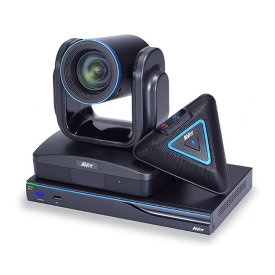
Installation Getting Familiar With the AVer EVC -Series EVC includes Main System, MIC, Camera and Remote Controller. MAIN SYSTEM Front Panel: Name Function (1) LED Indicator Show you the status of your LAN connection. Solid Green: LAN connection is successfully ... -
Page 8: Mic
audio signal output. (6) HDMI OUT Port Connect an HDMI cable from the HDMI monitor to HDMI OUT port located on the back panel. The HDMI interface allows you to transmit both audio and video signals over a single cable (HDMI cable). In dual screen configuration, the output screen connected to this port will be set up to primary screen automatically. -
Page 9: Camera
CAMERA Schematic diagram Name Function (1) IR Sensor Receive IR signal from the remote control for system operation. Amber light blinks when it detects key pressing event from remote. (2) CAMERA OUT Port Connect the camera cable to the CAMERA OUT port located on the back of camera and CAMERA IN port located on the back panel of main system for a video transmission. -
Page 10: Remote Controller
The remote controller requires two “AAA” batteries (included). Make sure the batteries are installed properly before using the remote controller. Aim the remote controller at the infrared sensor of your Aver EVC camera to remote control the unit. The remote controller included is only available for EVC-Series. - Page 11 (21) Layout Change the screen layout. (22) Aver Point Specified for some special functions. (Aver Point To be developed) (23) Preset a. Press and hold for 3 sec. to set the position of the camera to a preset from 0~99.
-
Page 12: Connections
Connections Before making the connections, make sure all devices are powered off. Refer to the illustrated connections below and also to the user manual of the device you are connecting to the AVer EVC-Series system. Make sure all connections have been connected successfully before powering on the system. -
Page 13: Connecting Monitors (Vga Out/Hdmi Out)
Locate the VGA/HDMI input port of the graphics display device and connect it to VGA OUT/HDMI OUT port of the AVer EVC with the supplied VGA/HDMI cable. You can configure the VGA OUT and HDMI OUT ports at the same time upon a dual screen configuration. -
Page 14: Connecting The Mic (Mic In)
Press the button on the top of AVer EVC-MIC to mute/un-mute the MIC. CONNECTING THE LAN (RJ-45) Connect the LAN port of AVer EVC to a RJ-45 wall jack or Ethernet hub with the supplied RJ-45 cable. It is requires an IP-based network before beginning LAN connection. -
Page 15: Connecting The Power (Dc 12V)
CONNECTING THE POWER (DC 12V) Connect the power adapter to a standard 100V~240V AC power outlet with the supplied power adapter and power cord. (1) To prevent shock, make sure all the connections on the main system are connected successfully before connecting the power cable and turning on the power. -
Page 16: Connecting The Audio (Audio In/Out)
CONNECTING THE AUDIO (AUDIO IN/OUT) AUDIO IN: Locate the AUDIO output port of the Laptop or Desktop and connect it to AUDIO IN port of AVer EVC with the supplied 3.5mm Audio cable. AUDIO OUT: Locate the AUDIO in port of the LCD TV speaker or normal speaker and connect them to AUDIO OUT... -
Page 17: Usb Storage (Usb Ports)
USB STORAGE (USB PORTS) EVC main system supports two USB2.0 interface for saving data. One is located on the front panel of main system; another is located on the back panel. [Note] The USB ports only support USB pen drive for F/W upgrading and saving log file; they DO NOT supply 5V power for any external devices. -
Page 18: Positioning The Mic
Positioning the MIC The best distance for EVC-MIC to receive audio signal is within 3m. Single Microphone Two Microphones... -
Page 19: Aver Evc Wizard Setup
AVer EVC Wizard Setup For the first time using AVer EVC system, the Installation Wizard will guide the user to setup EVC system step by step. After completing the wizard setup, user may start to use the EVC system. In Installation Wizard, user can use the following buttons on remote controller to move between the selections and make/confirm selection. -
Page 20: Language
LANGUAGE Select the language of the EVC system. Press to expand the drop-down list. Then, button to move the selection and press to make the selection. After selecting, press to move to Next option and press to go next step. SITE NAME Assign a name for EVC system. -
Page 21: Public Ip Configuration (Outside Of Firewall)
PUBLIC IP CONFIGURATION (OUTSIDE OF FIREWALL) Your EVC system is connecting directly to the internet. Select the IP mode. Obtain IP address by DHCP: Configure the system to automatically obtain an IP address from the DHCP server. The EVC system will automatically get a IP address which assigned by your DHCP server on LAN. -
Page 22: Private Ip Configuration (Behind Firewall Port Forwarding)
Select and enter the following information and click Apply to save the settings. To go to next step, click Next option and click Back to go back to Network Setting step. 1. Obtain Address is (1) Static IP: Configure the system to use the assigned IP address. - Page 23 Static IP: Configure the system to use the assigned IP address. Select this when the public IP address is available. Enter the following information and click Apply to save the settings. To go to next step, click Next and click Back to go back to Network Setting page. 1.
-
Page 24: Sip Setting
SIP SETTING Session Initiation Protocol (SIP) allows you around the world to communicate using your supported devices over the Internet. After setting network, user can choose to setup SIP or Skip SIP setting. To setup SIP, enter or select the following information 1. - Page 25 SIP SERVER REGISTRATION A typical SIP session involves a client requesting a session with a SIP server. After the request is received, the SIP server returns a response to the user indicating the availability of the session. After setting SIP, user can choose to setup SIP Server Registration or Skip. To setup SIP Server Registration, enter the following information and click Register to save the settings.
- Page 26 DATE AND TIME SETTING Setup the EVC system date and time. User can choose to use NTP server to adjust the date/time or manually enter the current date/time. NETWORK TIME PROTOCOL (NTP) Network Time Protocol (NTP) is a protocol that is used to synchronize system clock times in a network of device.
-
Page 27: Aver Evc Operation
Connecting the camera, microphone, main system, display and power, press the power button to turn on EVC. Power button starts blinking blue light, Aver logo shows up followed by an animation and music. In 30 seconds camera image and home screen appear on screen. Aim the remote controller to camera and start configuring AVer EVC. -
Page 28: Camera And Mic Icons
CAMERA AND MIC ICONS On the upper left-hand corner of your home screen, you may see camera and MIC indications. If the Camera connection is ok, is on the upper left corner of your home screen. Otherwise, “Camera Disconnected” warning message is displayed and screen is blue. -
Page 29: System Info
SYSTEM INFO Press (Info) button to switch to system information page. The System Info shows you the relative information about your EVC main system including Site Name, Model name, Maximum Allowable Sites, IP Address, MAC Address and System Version. Also, you can view call status while call is connected. - Page 30 Call Type AVer EVC supports H.323 and SIP calls. H.323 is commonly used to communication to other videoconferencing room systems. SIP is commonly used to communicate with other VoIP devices. Use the button to select...
- Page 31 Call Quality For the Call Quality selection, enter the desired call quality (or network bandwidth) from the drop-down list (default or 64K up to 4M bit per second). Select the “Call” on the Dial configuration screen then press to make a call. Make sure the network jack is plugged in and network is working properly before making a “Network...
-
Page 32: Phonebook
Phonebook Phonebook allows you to create and edit contact information, group contacts by category, search contacts then make a call. The group and contact (site) name in the directory will be sorted in alphabetical order. You may use the WebTool to edit or import the phonebook entries too. - Page 33 Enter the group name that you want to create. Select “Save” to save the new group. Or select “Cancel” to exit the “Input Group Name” dialogue box. The new group name will be saved and displayed in the group list. Search a Created Group Press “Yellow”...
- Page 34 If the name you enter has not been created, the system will show you “No Group Available”, please search again. If the Group data are over one page, you can also press “Green” button or “Blue” button to Page Up or Page Down. Edit Group Select Phonebook │...
- Page 35 The revised group name will be saved and displayed in the group list. If the revised name is the same as the saved name, the revised name will be ignored.
- Page 36 Add Contact from Group List Select Phonebook │ Group and press Select the Group name you want to add to Contacts List. Select “Edit Group” and press Confirm the Group Name what your want to add to the contracts list and then select “Contacts List”.
- Page 37 Select “Save" to save the Group name and added site to the contacts list. The selected Group name and added site will be added into the contacts list. Delete Group Select Phonebook │ Group and press Select the name you want to remove in the group list.
-
Page 38: New Site (Contact In Phonebook)
NEW SITE (CONTACT IN PHONEBOOK) New Site allows you to create and edit the information to each site. Add New Site Select Phonebook │ New Site and press Select the Group name, if you don’t want to add the entry into a group, please select “Non-Group”... - Page 39 Select the desired call quality value in the drop-down list. Select “Save” to store the newly added site contact. Edit New Site Select Phonebook │ Contacts List and press Select the contact you want to modify and press Select “Edit Site” and press In the Edit Site screen, you many change the Group name, Site Name, H.323.
- Page 40 The saved changes will be shown in the Group Site list. Delete New Site Select Phonebook │ Contacts List and press Select the contact you want to delete and press Select “Delete Site” and press Select “Yes” to remove the selected contact and “No”...
-
Page 41: Contacts List
“Blue” button to Page Up or Page Down. FAVORITE AVer EVC allows you save up to 10 most used contacts in the favorite list. Select Phonebook │ Favourite and press Select which line (0~9) do you want to save... -
Page 42: Call History
Call History The Call History allows you to check the incoming/outgoing calls made and their status. You can also make a call by selecting it in the Call History list. Call Status Select Call History and press The Call History will show you the IP address or the Site name with call type, Call Date/Time, Duration, and Call status. - Page 43 Make a Call From the Call History Select Call History and press Use the buttons to move the selection and scroll up and down in the call history list. and select “Call” to make a call. Press Or press button on the remote controller to make a call.
-
Page 44: General Setting
Confirm the Group selection then select “Save” to save the call entry into your contact. General Setting The General Setting allows you to modify system setting, check the system info, test the system and watch recorded conference files. CALL SETTINGS Call Setting allows you to enter or change your system’s site name which will appear on the screen during the call session for the other party to identify you. - Page 45 Default Call Quality EVC main system supports 64k, 128k, 256k, 384k, 512k, 768k, 1024k, 1152k, 1472k, 1536k, 1920k, 2048k , 3072k, 4096k selection for default call quality. By default, it is set to 512k. Enable/Disable AES Advanced Encryption Standard (AES) encrypts the data that is being transmitted during a video conferencing to provide protection against unauthorized data access.
- Page 46 By default, this function is disabled. Show Call Duration Enable/disable the call duration showing, by default, this function is enabled. Max. Transmitting/Receiving Bandwidth This function allows you to specify the maximum bandwidth of the outbound and inbound calls. Aver EVC system supports up to 4Mb.
-
Page 47: System Settings
SYSTEM SETTINGS System Settings allows you to set Language, the time for Auto Power off and enable/disable Keypad Tone function for your main system. Site Name Select General Setting │ System Settings and press . The site name is represented as name of this EVC system. - Page 48 Auto Power Off Mode Auto Power Off Mode allows you to set the time to power off your system automatically after idling. Select General Setting │ System Settings and press Select the time from the Auto Power Off Mode drop-down list (OFF/30Minutes/ 1Hour/2Hours/3Hours/4Hours).
-
Page 49: Administrator
ADMINISTRATOR Enable Web Admin Select General Setting │ Administrator and press Here allows you to enable administrator authority of Web Tool. When you access to Web Tool, a password is required. The default password is “1234”. Enable Admin Select General Setting │ Administrator and press Here allows you to enable authority of system administrator. - Page 50 Enable VCLine/ScreenShare Select General Setting │ Administrator and press Here allows you to enable function of VCLink and ScreenShare. Change VCLine/ScreenShare Password Select General Setting │ Administrator and press Here allows you to change password of VCLink ScreenShare. default password is “1234” Save System Log If you encounter unknown issues and are unsure of how to troubleshoot the unit, sending us the saved system log data to help us solve your problem faster.
- Page 51 Select “Run” located next to “Save System Log” to save the system log into your USB Flash drive. After the file is saved, select “OK”. Remove the USB Flash drive and insert it into your computer’s port. Located file message.tar.gz and send it to the technical support team.
-
Page 52: Monitor
Wake-On-LAN (WOL) Wake-on-LAN Ethernet computer networking standard that allows your computer to be turned on or awakened by a network message. By default, this function is disabled. MONITOR EVC main system allows you to connect dual monitor. In the Monitor configuration screen, you can configure the Aspect Ratio and Screen Saver to each monitor. - Page 53 Select Screen Saver time (OFF/10 Minutes/20Minutes/30Minutes/60Minutes) from the drop-down list and press . You can select “OFF” to disable this function or define a standby mode time. The screen will turn black when the system is in standby mode. Press any button on the remote controller to wake up the system.
-
Page 54: Date And Time
DATE AND TIME Date and Time allows you to set the Date and Time formats, adjust the time setting and change the Time zones around the world and countries. Date Format Select General Setting │ Date and Time and press Select Date Format... - Page 55 Enable NTP Network Time Protocol (NTP) is a protocol that is used to synchronize computer clock times in a network of computers. Select the Enable NTP check box to make your computer time the same as the network time. NTP Server The Network Time Protocol (NTP) allows administrators synchronize...
-
Page 56: Reset System
Year and Hour Enter the date and time including year, month, day, hour and minute that you want to show on the present system. Select “Apply” to active your settings. RESET SYSTEM The Reset System allows you to reset your main system to factory settings, which will clear phonebook entries and call history. - Page 57 Default Setting Reset: LAN configuration, video/audio codec selection, call settings and so on will be reset. Click “Yes” to reset your system to factory default values. Clear Phonebook: All the phonebook entries saved in the system will be deleted. Click “Yes” to delete all content of your phonebook.
-
Page 58: Default Layout
DEFAULT LAYOUT You can select the layout for call conference. There two type of layout – Layout without content and Layout with content. Layout without content: Only display call video, no content share screen. There 4 layouts can be chosen. During the call conferencing, the display layout will be the layout that you has chosen. -
Page 59: Video/Audio
Video/Audio In Video/Audio configuration screen, you can set the MIC gain level, select the preferred video and audio codecs and adjust the camera functions. CAMERA Camera allows you to set the White Balance, Exposure and Frequency for your camera. White Balance Whit balance is a camera setting that adjusts for lighting in order to make white objects appear white in photos. - Page 60 Exposure A photograph’s exposure determines how light or dark an image will appear when it is been captured by your camera. Select the exposure level you prefer from 1 to 9 or auto. Frequency Select correct frequency setting (Auto/50Hz/60Hz/OFF) form the Frequency drop-down list.
-
Page 61: Microphone
If MIC Input Source is Audio in, only “far site” can be heard the audio sound. [Note] When audio input port is connected with audio device and enable “Sending Audio Via Line-in to” function, the AVer MIC is disabled. -
Page 62: Video/Audio Codecs
Broadcast Support(HDMI) This function allows you to hear own talking voice during video conferencing through the stream media device that is connected on HDMI port of EVC main unit. In MIC Input Source, please select “MIC In”. If the stream media device didn’t connect to HDMI port of EVC main unit, it will cause howling when voice come out from TV or speaker. - Page 63 For Audio: G.728, G.722.1C, G.722.1*, G.722, G.711. ® *:G.722.1/G.722.1C, licensed from Polycom Please contact system administrator if you have any question on these codecs.
-
Page 64: Network
LAN CONFIGURATION AVer EVC supports IPv4 and IPv6 internet protocol for your configuration. IPv4 is the most widely deployed internet protocol used to connect devices to the internet. IPv4 uses a 32-bit address scheme, written in decimal as four numbers separated by periods. Each number can be zero to 255. - Page 65 IP Address Type DHCP: Configure the system to automatically obtain an IP address from the DHCP server. Static IP: Configure the system to use the assigned IP address. Select this when the public IP address is available. Your IP address is Show the current IP address;...
- Page 66 Default Gateway A gateway is a network point that acts as an entrance to another network. Enter the gateway address when system does automatically obtain the gateway. Preferred/Alternate DNS Server Domain Name System (DNS) servers convert human friendly names (for example: www.example.com) addresses...
-
Page 67: Lan Configuration (Ipv6)
LAN CONFIGURATION (IPV6) IPv6 is an evolutionary upgrade to the Internet Protocol. IPv6 will coexist with the older IPv4 for some time. IPv6 addresses are 128-bit IP address written in hexadecimal and separated by colons. An example IPv6 address could be written like this: 300E:1389:3030:72EB:1D71:414B:1079:6AF3. Some types of addresses contain long sequences of zeros that can be compressed (the address of fc00:0000:0000:0000:0000: 0000:0000:0001 can be compressed to fc00::1. - Page 68 Your IP Address is Show the current IP address; enter into when you need to configure your IP address manually. Prefix Length Prefix Length allows you to place as many IPv6 devices as the underlying network medium allows. After finishing all settings, select “Apply” to active the changed settings.
-
Page 69: Firewall
FIREWALL Configure the following items to setup the Firewall. Select Network │ Firewall and press Configure the following relative items to setup the Firewall. TCP/UDP Ports By default, the system communicates through TCP/UDP ports in the range from 30000 to 30019. - Page 70 Enable UPnP Enable/disable UPnP function. NAT Configuration AVer EVC supports NAT systems that use the internal IP addresses to communicate with other devices outside the LAN. NAT Public (WAN) Address The NAT public address must be entered when you enable the feature on NAT configuration.
-
Page 71: Sip
Session Initiation Protocol (SIP) allows you around the world to communicate using your supported devices over the Internet. Select Network │ SIP and press Configure the following relative items to setup the SIP. SIP Site Name Enter the SIP site name for others to identify. The SIP site name may be the same or different then the domain for Web activity. - Page 72 SIP Transport Protocol Select the SIP Transport Protocol type from the drop-down list for using. There are two types of Internet Protocol (IP) traffic. They are Transmission Control Protocol (TCP) and User Datagram Protocol (UDP). To ensure proper connection, verify if both calling parties are using the same transport protocol.
- Page 73 Enable SIP Select Enable SIP check box and press to activate/deactivated using SIP. BFCP Enable presentation sharing function in SIP. It allows you to share the presentation file screen to other caller in video conference meeting. If connection is not so stabled, use TCP mode can offer a reliable connection to prevent unexpected disconnection and behaviors due to packet losses.
- Page 74 STUN Port Enter port number of STUN server. Enable STUN Server Mark to enable STUN server function.
-
Page 75: Sip Server
SIP SERVER A typical SIP session involves a client requesting a session with a SIP server. After the request is received, the SIP server returns a response to the user indicating the availability of the session. Select Network │ SIP Server and press Configure the following relative items to setup the Server. - Page 76 Authorization Name Select Terminal Name and press to enter authorization name. Password Select Password and press to enter using password. Registrar Server Registrar Server accepts registrations from users and places these registrations, (which is essentially location information), in a database known as a location service.
- Page 77 Proxy Server Proxy Server is computing device (typically a server) that interfaces between data processing devices and others within a communications network. These devices may be located on the same local area network or an external network. Enter the used Proxy Server name.
-
Page 78: Gatekeeper
GATEKEEPER The Gatekeeper in AVer EVC serves the purpose of translating services from E.164IDs to IP addresses in an H.323 network. Select Network │ Gatekeeper and press Configure the following relative items to setup the Gatekeeper. H.323 Name Specify the name that gatekeepers and gateways can use to identify this system. - Page 79 H.323 Extension Enter a numeric value for the gatekeeper to identify your system further. Gatekeeper IP Address Enter the IP address for the gatekeeper server. Connect to Gatekeeper Select this check box to Activate/deactivate gatekeeper. Make sure to setup the Gatekeeper before setting up the Firewall.
-
Page 80: Test
Enable H.460 Firewall Traversal If you want to enable the H.460 Firewall Traversal, please set the following ports in port forwarding your firewall before start installing your EVC. Make sure your gatekeeper supports H.460 Firewall Traversal before enabling it. TEST This feature tests the network ability between local and far site. -
Page 81: Web Configurations
Web Configurations You can use the internet browser to access your AVer EVC system through a LAN RJ-45 cable to setup a AVer EVC system remotely. You can also access the Phonebook to add, edit and delete entries, view and download the call history, update the system, and restore your previous settings. For web configurations, your AVer EVC system default IP address is: 192.168.0.1. - Page 82 After login, user should see the video screen of local site. is indicated in background view mode. is indicated in live view mode. Click icon can call out on-screen remote controller. You can use mouse to click the on-screen remote controller to operate functions on WebTool. Click button can switch to numeric pad and phonebook button.
-
Page 83: Managing Phonebook
You can use the mouse to click the specified icon for a selection. Managing Phonebook In the Phonebook page of WebTool, all functions are the same as your AVer EVC Application. One different is the Upload/Download. EDIT AND SAVE 1. -
Page 84: Download Phonebook Entries
EVC system. UPLOAD PHONEBOOK ENTRIES Upload allows you to upload the data that you have edited or added from your WebTool to your AVer EVC system. Click Phonebook │ Upload/Download Click “Upload Phonebook” to upload... -
Page 85: Update System
Update System UPDATE SYSTEM You can update the latest EVC firmware to your AVer EVC system from AVer EVC WebTool. Click General Setting │ System Update Click “System Update”. Click “Select” to browse and locate the downloaded firmware file .dat. -
Page 86: Ez Join
In Dial screen, you has option to create few entries for most commonly used bridge/cloud call. Those entries are defined by a XML config file. Please contact the AVer support team (SOBU.Support@aver.com) to get the XML config file. You can modify sample XML to fit their environment, upload it by Web Tool. -
Page 87: Making A Call
Making a Call There are 3 methods to make a video call. Select the site contact in the Phonebook list, dialing the IP address or select a previous call in the Call History list. Using the Phonebook Select Phonebook│Contacts List and press Select the site contact in the Group-Site list and press to make a call. -
Page 88: Using Dial
Using Dial Select Dial│Dial and press Use the remote controller to enter an IP address and select “Call” to make a call. The call will be connected... -
Page 89: Using Call History
Using Call History Select Call History│Call History and press Select the site you want to call in the call history and press The call will be connected. If the call fails, the IP address may have been entered incorrectly, the far site is set to Do not Disturb mode or the far site hung up the call. -
Page 90: Scenarios For Lan Connection
Scenarios For LAN Connection Public IP Configuration (Outside of Firewall) Your EVC system is connecting directly to the internet. 1. From the remote press “Home”-> “ ” -> “Setting”. 2. Press “ ” -> “Network”. 3. Press “LAN Configuration”. 4. And In the drop-down list “Obtain IP address”, choose “Static IP”... - Page 91 PPPoE: Input the PPPoE login “User name” and “Password”. 5. Select “Apply” and press (Enter). 6. Press “Home” on the remote to return to the home menu. Press the (Call) button on the remote and you are ready to make your first call.
-
Page 92: Private Ip Configuration (Behind Firewall With Port Forwarding)
Private IP Configuration (Behind Firewall with Port Forwarding) Please make sure you have set the following ports in port forwarding in your firewall. Port Function Type 1719 Gatekeeper 1720 H.323 Call setup Signalling and control for 30000~30019 audio, call, video and TCP and UDP data/FECC HTTP... - Page 93 3. Press “LAN Configuration”. 4. And In the drop-down list “Obtain IP address”, choose “Static IP”. 5. Manually input the “IP address”, “Subnet Mask” and “Default Gateway”. 6. Select “Apply” and press (Enter). 7. Press (Back) on the remote to return to previous menu.
-
Page 94: H.460 Gatekeeper With Firewall Traversal
H.460 Gatekeeper with Firewall Traversal Your EVC system is connecting to the internet through a firewall and your have a Gatekeeper outside the firewall. 1. From the remote press “Home”-> “ ” -> “Setting”. 2. Press “ ” -> “Network”. 3. - Page 95 8. Enter the IP address of your Gatekeeper in the “Gatekeeper IP Address” field and enable the “Use Gatekeeper” check box. 9. Enable the “Enable H.460 firewall Traversal” option. 10. Press the “Home” button on the remote to return the home menu. 11.
-
Page 96: Troubleshooting
ISP. - There is a routing issue if you installed two Aver EVC systems sharing one public IP address. Unable to connect to other Video Conferencing systems. -
Page 97: Network
Network 1. The LAN connection is fail. - Make sure you have changed your default IP address. The default IP address is 192. 168.0.1, in order not to conflict with other devices in the same LAN, please change your IP address at the start. - Page 98 6. Disable intranet sites in Compatibility View. Go to “Tools │ Compatibility view settings”. 7. Unclick the checkbox “Display intranet sites in Compatibility View” and then click “Close”.
-
Page 99: Others
Ensure you are not calling to a system that has already up to maximum call-in limitation. 2. Forget the administrator password. Please contact Aver technical support for assistance. 3. Unable to control the far end camera. Make sure the “Cam Ctrl”... -
Page 100: Limited Warranty
Except for the foregoing, the Product is provided “AS IS.” In no event does AVer warrant that You will be able to operate the Product without problems or interruptions, or that the Product is suitable you’re your purposes. Your exclusive remedy and the entire liability of AVer under this paragraph shall be, at AVer’s option, the repair or... -
Page 101: Limitation Of Liability
CONNECTION WITH THIS LIMITED WARRANTY, OR THE USE OR PERFORMANCE OF ANY PRODUCT, WHETHER BASED ON CONTRACT OR TORT, INCLUDING NEGLIGENCE, OR ANY OTHER LEGAL THEORY, EVEN IF AVER HAS ADVISED OF THE POSSIBILITY OF SUCH DAMAGES. AVER’S TOTAL, AGGREGATE LIABILITY FOR DAMAGES OF ANY NATURE, REGARDLESS OF FORM OF ACTION, SHALL IN NO EVENT EXCEED THE AMOUNT PAID BY YOU TO AVER FOR THE SPECIFIC PRODUCT UPON WHICH LIABILITY IS BASED. -
Page 102: Ce Class A (Emc)
Copyright © 2015 by AVer Information Inc. All rights reserved. No part of this publication may be reproduced, transmitted, transcribed, stored in a retrieval system, or translated into any language in any form by any means without the written permission of AVer INFORMATION Inc.
Need help?
Do you have a question about the EVC Series and is the answer not in the manual?
Questions and answers