AVer MT300 User Manual
Matrix tracking box
Hide thumbs
Also See for MT300:
- User manual (92 pages) ,
- Quick start manual (19 pages) ,
- User manual (35 pages)
Table of Contents
Advertisement
Quick Links
Advertisement
Table of Contents

Subscribe to Our Youtube Channel
Related Manuals for AVer MT300


Summary of Contents for AVer MT300
- Page 1 MT300 Matrix Tracking Box — — User Manual...
- Page 2 Risk of Explosion if Battery is replaced by an Incorrect Type. Dispose of Used Batteries According to the Instructions. COPYRIGHT © 2023 AVer Information Inc. All rights reserved. | September 8, 2023 The information contained in this documentation is subject to change without notice.
- Page 3 Tel: +81 (0) 3 5989 0290 テクニカル・サポート: https://jp.aver.com/technical-support Vietnam Branch Office Công ty TNHH AVer Information (Việt Nam) Tầng 5, 596 Nguyễn Đình Chiểu, P.3, Quận 3, Thành phố Hồ Chí Minh 700000, Việt Nam Tel: +84 (0) 28 22 539 211...
-
Page 4: Table Of Contents
Get Started ........................7 Web Interface Setup ....................7 Main Page ........................8 Add a Device....................... 9 Set up Your MT300 ....................... 11 Live Mode ......................... 11 Manual Mode ......................12 Auto Mode (Channel) ....................14 Auto Mode (Active Position) ..................17 Video ......................... - Page 5 Appendix ........................31 Supported AVer Cameras..................31 Supported Microphones .................... 32 HTTP Requests ......................40 TCP Requests ......................40...
-
Page 6: Overview
Overview Package Contents MT300 Power Adapter & Cable Ties (x13) Cable Fixing Plate Matrix Tracking Box Power Cord (x2) 3.0 x 5mm M3 x 10mm Rack Mount Bracket 3.0 x 5mm Flat Head Screw (x5) Screws (x4) (x2) Truss Head Screw (x4) USB 3.0 Cable (x2) -
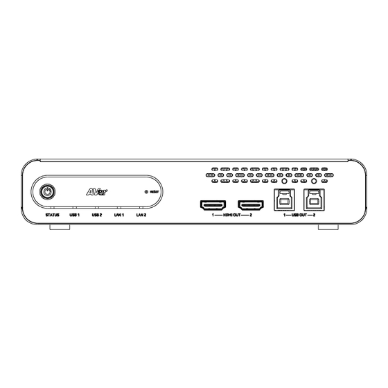
Page 7: Parts Info
Parts Info Front Panel Back Panel 1. Power Button 6. DC Power Jack 2. Reset Button 7. PoE+ Port IEEE 802.3AT 3. LED Indicators 8. Ethernet Port 4. HDMI Out Port (x2) 9. HDMI In Port (x3) 5. USB Out 3.0 Type-B Port (x2) 10. -
Page 8: Led Indicators
LED Indicators STATUS Color Status Solid orange Standby Solid green Normal Flashing green Firmware upgrade USB 1, USB 2 Color Status Solid green Connected Flashing green Streaming LAN 1, LAN 2 Color Status Solid green Connected Dimensions... -
Page 9: Connections
Connections Front Panel Back Panel Network... -
Page 10: Installation
Installation Cable Fixing Plate Installation 1. Secure the cable fixing plates to the tracking box with 5 flat hat 3.0 x 5mm screws in the package. 3. Use 13 cable ties in the package to secure 2. Plug in cables. the cables and cable fixing plates. -
Page 11: Desk Mount Installation
Desk Mount Installation 1. Secure the mount brackets on the tracking box. Screw: 4 truss head screws, 3.0 x 5mm 2. Install the mount brackets and the tracking box under the desk. Screw: 4 screws, M3 x 10mm Server Rack Mount (Optional Accessories) For details on optional accessories, consult your local dealer. -
Page 12: Get Started
(https://www.aver.com/download-center). 2. Connect your tracking box to the network using the PoE+ port. 3. Make sure your device and the computer running AVer IPCam Utility are on the same network. 4. Open AVer IPCam Utility. Click Search. 5. Enter the default username/password admin/admin in the Login field. -
Page 13: Main Page
Main Page 1. Live Mode Toggle Live Mode on or off. 2. Select profile Choose a defined profile. While you can save Auto Mode and Manual Mode settings in the same profile, only one mode is applied per use. ... -
Page 14: Add A Device
Add a Device To add cameras and microphones: 1. Click the Settings icon on the main page > Device > Add device. 2. Fill out the Add New Device dialog box. Item Description Select Camera or Microphone Add a camera or a microphone. ... - Page 15 3. Click Save. To edit devices: 1. Hover over the device and click the Pencil icon. 2. Edit device in the dialog box and click Save. To delete devices: Hover over the device and click the Trash can icon.
-
Page 16: Set Up Your Mt300
Set up Your MT300 The modes built into your MT300 help you present video feeds in a single stream composited gallery, follow the presenter in real time as they move, or frame the active talker. Choose from Live Mode, Manual Mode and Auto Mode. -
Page 17: Manual Mode
Manual Mode Follow the presenter in real time as they move using presets and Human Tracking modes. Create a profile to save your Manual Mode settings: You can rename a profile. While you can save Manual Mode and Auto Mode settings in the same profile, only one mode is applied per use. - Page 18 Human Tracking For supported AVer cameras, refer to <Supported AVer Cameras>. For camera settings, refer to your AVer camera’s user manual. Human tracking includes three modes: Presenter Zone Hybrid Presenter Mode example: 1. Both microphone channel 1 and preset 1 are set to the whiteboard.
-
Page 19: Auto Mode (Channel)
Auto Mode (Channel) Frame the active talker with voice-tracking functionality by linking AVer cameras with third-party microphone systems (supported models) from Audio-Technica, Biamp, ClearOne, Nureva, Sennheiser, Shure and Yamaha. Third-party microphone systems may require setup in their manufacture software. For details on settings, please refer to <Supported... - Page 20 Select Group The Select group menu includes: Device status: Click the question mark icon for reference. Camera is sending data to MT300 Device online Device offline Incorrect account or password Group +: Add a camera and microphone group.
- Page 21 Pair Microphone Channels with Presets 6. Select a device group in Select group. A blue frame indicates that it is selected. 7. Select a preset from the Select preset drop-down list under Camera for each microphone channel. 8. Select a Human Tracking mode. Refer <Human Tracking>...
-
Page 22: Auto Mode (Active Position)
Active Position supports: USB-connected AVer cameras Shure MXA920 Ceiling Array Microphone To set up Active Position: 1. Make sure the USB-connected AVer camera has been paired with a Shure MXA920 in <Add a Camera and Microphone Group>. - Page 23 Step 2 5. Align the red line with the top or bottom edge of the microphone by dragging the red dot. Click the question mark for reference. 6. Adjust the camera angle using pan, tilt and zoom controls, if the microphone appears at a slight angle.
- Page 24 Step 3 8. Starting with the upper left, locate 3 microphone corners in a clockwise direction. Click the question mark for reference. 9. Move the red cross to the 1 corner (upper left) in the live view using pan, tilt and zoom controls.
- Page 25 12. Finally, locate the logo on the microphone to indicate its orientation. Move the red cross to the logo in the live view using pan, tilt and zoom controls. Depending on the microphone orientation, the logo corner may be the same as one of the 3 corners.
- Page 26 To adjust or add a coverage area: 1. Open the MXA920 web application. 2. Go to Settings > General > Automatic coverage. 3. To add a mix of up to 8 dynamic and dedicated coverage areas, turn on Automatic coverage. ...
-
Page 27: Video
Video Select the Settings icon on the main page > Video. Item Description Video Output Resolution Choose a video output resolution. Stream Video Output Choose a streaming output resolution for the live view. Framerate Choose a framerate. Bitrate Choose a bit rate. Encoding Type Choose H.264 or H.265. -
Page 28: Network
Toggle DHCP on or off. Hostname Enter a hostname that is displayed on devices such as an IP router. The default is AVer. IP Address Enter your network settings to set up a static IP connection. Toggle off DHCP first. - Page 29 RTMP Settings Stream live video to a video platform such as YouTube. To enable live streaming on YouTube: 1. Go to YouTube. 2. From the top right, click Create > Go live. 3. Copy and paste your YouTube server URL and stream key into the web interface. 4.
-
Page 30: Ndi
Network Device Interface (NDI) is a protocol that transmits high-quality, low-latency video and audio streams over IP networks. Tracking box comes in two models: MT300 (without NDI) and MT300N (with NDI). To purchase NDI|HX upgrade, please visit NewTek Online Store (https://store.newtek.com/ndi-hx-upgrade-for-cameras.html#). - Page 31 Multicast Server Select the checkbox to enable multicast server to allow efficient distribution of NDI streams to multiple receivers without overwhelming the network. Multicast Server Address Enter the IP address of a group of recipients that receive NDI streams from a multicast server. Multicast Server Mask Enter the network mask to specify the range of IP addresses that are eligible to receive NDI streams.
-
Page 32: System
Select the Settings icon on the main page > System. Item Description MT300 Information Display MT300 information such as the IP address. Upgrade Firmware Download the latest firmware from AVer Download Center (https://www.aver.com/download-center). Schedule Date/Time: Set date and time for your tracking box. -
Page 33: Help
Help View our user manual, terms and conditions, and private policy. Select the Settings icon on the main page > Help. -
Page 34: Specification
Specification DC Power 12V/1.5A PoE+ 42.5-57V / 0.6A Reset Button 3, Type-A for peripherals input USB Inputs #1,#2 are UVC only #3 can be UVC or UAC 2, Type-B for user application Non-simultaneous output Automatic switch to the port that is connected to host. Port #1 has USB Outputs higher priority if both ports are connected to host (PC or MTR),. -
Page 35: Troubleshooting
Troubleshooting No human tracking. Make sure your camera supports human tracking. For supported AVer cameras, see Supported AVer Cameras. If your camera is connected via HDMI and controlled via RS-422, make sure you select “Support Human Tracking” from the drop-down list. Hover over the device in the Device list and click the Pencil icon to edit. -
Page 36: Appendix
Appendix Supported AVer Cameras Professional Tracking Cameras (US model name in italics) PTC300 V2 Series PTC300 Series PTC500 Series PTC115 Series PTC330UV2 PTC330 PTC500S PTC115 TR333V2 TR331 TR530 TR320 PTC320UNV2 PTC330N PTC500+ PTC115+ TR323NV2 TR331N TR530+ TR320+ PTC320UV2 PTC330U TR333... -
Page 37: Supported Microphones
Supported Microphones Some models may require setup in their manufacture software before using PTZ Link. Audio-Technica ATND1061 Beamforming Ceiling Array Microphone Digital Microphone Manager 1. Go to Settings & Maintenance > System Settings > Network > IP Control Settings. 2. Turn on Notification and Camera Control Notification. - Page 38 ClearOne BMA 360 Microphone System CONVERGE® Pro 2 (supports up to 3 daisy-chained BMA 360s) MT300 1. PTZ Link assigns 12 channels to each BMA Daisy-Chained Channel Start/End 360. BMA 360 1-12 BMA 360 13-24 Unused channels are retained in the...
- Page 39 HDL410 Nureva Console Client 1. Turn on Enable camera tracking integration. 2. Enter the IP address of MT300 in the Allowed host names / IP addresses field MT300 3. MT300 divides HDL microphones’ horizontal angles into 8 equal parts, which correspond to MT300 channel 1-8.
- Page 40 2. Click Channel Configure to choose a Pickup Mode. Direction: The microphone’s horizontal angles are divided into 8 equal parts, which correspond to MT300 channel 1-8. Coverage: Add a dedicated coverage area. 3. Select Coverage from the Pickup Mode drop-down list.
- Page 41 TeamConnect Ceiling 2 Sennheiser Control Cockpit An Exclusion Zone set in Sennheiser Control Cockpit also affects the corresponding channel in MT300 as illustrated. MT300 MT300 divides TeamConnect Ceiling 2’s horizontal angles into 8 equal parts, which correspond to MT300 channel 1-8.
- Page 42 1. Open the Configuration tab. 2. Select a template from the multi-channel options. Or select Add Channel to add more than 1 channel. MT300 does not support single channel for the MXA310. MXA910 Ceiling Array Microphone Web Application 1. Go to IntelliMix > Automixer Properties >...
- Page 43 The default setting is a 30 by 30 foot (9 by 9 meter) dynamic coverage area. 3. To add more coverage areas, go to Coverage > Add coverage. MT300 4. Go to Auto Mode Settings > Channel. 5. Click Channel Configure to choose a Pickup Mode.
- Page 44 RM-CR Remote Conference Processor RM-W Wireless Microphone System MT300 1. MT300 voice tracking function requires linking more than one RM-TT or RM-W microphones for location data. 2. If you link these microphones to the RM-CR Remote Conference Processor, enter the processor’s...
-
Page 45: Http Requests
Address]/request=enable&group=[Group ID] Query status of a specified group http://[account]:[password]@[IP Address]/request=queryStatus&group=[Group ID] Set profile http://[account]:[password]@[IP Address]/request= setProfile&profile=[number] Reboot http://[account]:[password]@[IP Address]/cgi-bin?OnePush=! TCP Requests A TCP command string starts with AVER:[account]:[password]/request=X. X is as HTTP requests above. For example, AVER:[account]:[password]/request=pause, AVER:[account]:[password]/request=resume, and so on.
Need help?
Do you have a question about the MT300 and is the answer not in the manual?
Questions and answers