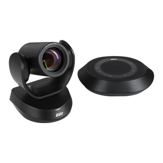
AVer VC520 Pro User Manual
Hide thumbs
Also See for VC520 Pro:
- Instruction manual (53 pages) ,
- Quick installation manual (11 pages) ,
- User manual (68 pages)
Table of Contents
Advertisement
Advertisement
Table of Contents

Related Manuals for AVer VC520 Pro


Summary of Contents for AVer VC520 Pro
- Page 1 VC520 Pro User Manual...
- Page 2 ©2020 AVer Information Inc. All rights reserved. All rights of this object belong to AVer Information Inc. Reproduced or transmitted in any form or by any means without the prior written permission of AVer Information Inc. is prohibited. All information or...
- Page 3 Do not mix and use different types of batteries: alkaline, standard (carbon -zinc) or rechargeable (nickel-cadmium). Do not dispose of batteries in a fire. Do not attempt to short-circuit the battery terminals. Contact Information AVer Information Europe B.V. Global Westblaak 140, 3012KM, AVer Information Inc. AVer Information Inc.
-
Page 4: Table Of Contents
Remote Control ....................... 7 Installation ....................... 9 Device Connection ....................9 RS232 Connection ....................11 Wall Mount Installation ..................17 Operating the Camera ..................20 Make a Video Call ....................20 Make a Connection by AVer IP Finder App ............20... - Page 5 Use SmartFrame Function ................22 What is SmartFrame? ................... 22 Two kinds of SmartFrame Function .............. 22 How does SmartFrame Work ................ 23 Login ......................24 Live Screen Operation................... 25 Setup the Preset .................... 25 Select the Preset Position ................27 Camera Settings ....................
- Page 6 True WDR ....................32 Frequency ....................32 White Balance ..................33 Noise Reduction ..................33 Brightness ....................34 Sharpness....................34 Saturation ....................35 RS232 Setting ....................35 Video Format Setting ..................36 IP Stream Resolution ................36 Frame Rate .................... 36 Bit Rate ....................
- Page 7 Echo Cancellation .................. 50 Keyboard Noise Suppression ..............50 Phone In Jack ..................51 Operating the AVer PTZApp .................. 52 Install AVer PTZApp ....................52 Use AVer PTZApp to Setup the Camera ............... 52 Set the Camera Number ................60...
- Page 8 Hotkey Control ....................62 Home / Sleep Position ................... 63 ADDR / Protocol / Baud Rate ................ 63 OpenGL ......................64 Use AVer PTZApp to Setup the Speakerphone ............ 65 Use AVer EZLive ....................66...
-
Page 9: Package Contents
Package Contents Power Adapter Camera Unit Speakerphone Unit Remote Control Power Cord* Speakerphone 3.5 mm Audio L-Mount Screws for USB 3.0 Cable Cable (10m) Cable (0.9m) Bracket Mount M4 x 8mm(x2) 1/4”-20 L=7.5mm(x2) Drilling Paper Quick Guide Warranty Card 46.00[1.81] Ø5.50[Ø0.22] 51.00[2.01] P/N: 303AU340-AGR... -
Page 10: Product Introduction
Product Introduction Overview Status LED USB3.1 Type B port Power on: Red light RS232 in/out port Standby: Orange light Ethernet port IR sensor DC 12V power jack Speakerphone port(Blue cable) Kensington Lock 9 1011 12 Speakerphone port Phone in port (For extended speakerphone Line out port and microphone connection/... -
Page 11: Expansion Speakerphone/Microphone Connection
Expansion Speakerphone/Microphone Connection There are 2 types of expansion solutions that can be extended from the VC520 Pro speakerphone. Please purchase the expansion speakerphone and/or microphone directly from AVer or an AVer reseller. Expansion Speakerphone Requirements: VC520 Pro Firmware version: 1000.84 or later FONE540 Firmware version: 7000.30 or later... -
Page 12: Phone In Connection
[Note] The VC520 Pro can support up to four expansion microphones, however, the daisy-chain expansion cable cannot exceed over 40m in total. Phone in Connection Users can connect a mobile phone to the Phone in port on the speakerphone as a hands-free speaker. -
Page 13: Audio Signal Receive Range
Audio Signal Receive Range The best distance for the speakerphone to receive audio signal is within 7.5ft in radius. When connecting two or more speakerphones, the distance between the speakerphones must be 9ft. -
Page 14: Speakerphone Led Indicator
Speakerphone LED Indicator Button LED Indicator Status White light Adjust the volume up and down. When adjusting the volume up and down, the volume LED indicator will light up in blue. White/Blue light Touch to mute/un-mute the speakerphone volume. In mute status, the LED indicator will light up in red. -
Page 15: Remote Control
Remote Control Name Function 1. Camera Select One remote can control up to 3 AVer VC/CAM/VB series cameras. You can use AVer PTZApp to set numbers associated with each camera, and then select which camera you would like to control using the remote. - Page 16 SmartFrame function on/off. 8. Brightness - Decrease the brightness. 9. Call/answer* Answer a call or start a call. 10. Enter Not supported for VC520 Pro. 11. Mute/Unmute Mute/Unmute the speakerphone. Speakerphone* 12. Volume Up/Down* Adjust volume up or down. 13. Preset Hot Key Press to move to a preset position previously set by the user.
-
Page 17: Installation
Installation Device Connection Connect the camera to power outlet. Connect the camera to the speakerphone using the speakerphone cable included in the package. [Note] The speakerphone port of the camera and the camera port of the speakerphone are both marked in blue. - Page 18 Connect other necessary cables. [Note] USB and RS232 cable need to secure the cable with attached screw. Make sure the cable is well connected to the connector on the camera before securing the cable. Connect the camera to the computer. [Note] Use the USB 3.0 cable that is included in package.
-
Page 19: Rs232 Connection
RS232 Connection Camera RS232 Port Pin Definition Mini DIN9 Function I/O Type Signal Description PIN # Output Data Terminal Ready Input Data Set Ready VISCA IN Output Transmit Data Input Receiver Data Output Data Terminal Ready Input Data Set Ready VISCA OUT Output Transmit Data... - Page 20 Computer/Keyboard Controller and Camera Connection Direct Connection If users don’t buy AVer RS232 adaptor cable, please refer to the pin connection shown below. Mini DIN9 Cable Camera controller Camera Controller/PC (Mini DIN9) (DB9) 1. DTR(IN) 1. DCD 2. DSR(IN) 2.
- Page 21 Use the RS232 mini DIN9 to mini DIN8 cable (Sold separately. Please purchase from AVer.). Users can purchase AVer RS232 min DIN9 to mini DIN8 adaptor cable* to connect with Computer or keyboard/controller. * RS232 (mini DIN9 to mini DIN8) adaptor cable (PN: 064AOTHERCDC)
- Page 22 RS232 mini DIN9 to mini DIN8 Cable Pin Definition Mini DIN9 Connect to AVer camera IN(Mini DIN8) Connect to next camera Connect to controller or PC OUT(Mini DIN8) Mini DIN8 Pin Definition...
- Page 23 Camera Cascade Connection Direct Connection If users don’t buy AVer RS232 adaptor cable, please refer to the pin connection shown below for cascading cameras. Total can connect up to 7 cameras. Camera 1 Camera 2 (Mini DIN9) (Mini DIN9) 1.
- Page 24 Connect camera with AVer mini DIN9 to mini DIN8 adaptor cable. Connect the mini DIN8 female side to male mini DIN8 Visca cable (Users have to buy it in the market) and then connect AVer mini DIN9 to mini DIN8 adaptor cable again to connect to next camera.
-
Page 25: Wall Mount Installation
Wall Mount Installation 1. Use the drilling paper included in the package to drill the holes in the wall where the user wants to mount the camera. 46.00[1.81] Ø5.50[Ø0.22] 51.00[2.01] P/N: 303AU340-AGR 2. Use the screw to secure the L-mount bracket on the wall. Screw ... - Page 26 3. Then, assemble the + B L-mount bracket with screws (included in package). Screw: M4 x 8mm(x2) 4. After assembling the L-mount bracket, secure the lower part of L-mount bracket on the wall. Screw For Cement wall: M4 x20mm self-tapping screws(x2) + Plastic conical anchor ...
- Page 27 5. Pass the cables through the hole on the L-mount bracket and connect the cables to corresponding connection ports. 6. Use the remaining screws (included in package) to secure the camera on the L-mount bracket. 1/4”-20 L=7.5mm(x2) Screw:...
-
Page 28: Operating The Camera
AVer PTZApp, refer to the AVer PTZApp section in this user manual. Make a Connection by AVer IP Finder App User can use AVer IP Finder app to find the camera and make a connection through the browser to configure the camera. - Page 29 4. Select a camera from the list. The corresponding fields of IP address will display. 5. To change the IP address of camera, user can select “DHCP” or “Static IP”. The DHCP should get the IP address from local dynamic IP sever. The static IP, user can enter the specific IP address.
-
Page 30: Use Smartframe Function
Use SmartFrame Function What is SmartFrame? SmartFrame uses face detection technology. While in a conferencing meeting, participants must face the camera for face detection. Side face (one ear/ one eye) is not detectable. The effective distance to get best performance is at maximum 4.5meters Two kinds of SmartFrame Function ... -
Page 31: How Does Smartframe Work
How does SmartFrame Work Manual frame: Press and hold down the button and will pop up on the top left corner of the Image screen. This indicates for all participating users to sit facing towards the camera to allow it to detect all faces present. After 3 to 5 seconds, the camera will calibrate and automatically zoom to include all users to fit in the screen. -
Page 32: Login
Login To find the IP address of the camera; please refer to “Make a connection by AVer IP Finder App” section. 1. Open the browser on your laptop/PC and enter the IP address of the camera. -
Page 33: Live Screen Operation
Live Screen Operation User can control the camera direction, zoom in/out, and preset selection. [Note] The system will force the previous login to log out, when there is a second login. Functions list Preset selection Preset positon display Logout the Web interface Live screen Preset setups, directional buttons,... -
Page 34: Setup The Preset
Setup the Preset User can set 10 preset positions. 1. In live screen, select to expand preset position list. 2. Select the preset number frame(0~9). 3. Use ▲, ▼, , and zoom in/out button adjust the camera screen view to desired position. 4. -
Page 35: Select The Preset Position
Select the Preset Position Preset positions need to be set. Select to expand the preset position list and select the preset user wants. The live screen will move to the preset screen view. Use mouse to scroll up or down to select the preset. Select to close the preset position list. -
Page 36: Camera Settings
Camera Settings Smart Frame One-click automatic FOV(field of view) adjustment to fit all participants. In live screen view, select Setting > Camera > Smart Frame > Auto, Manual or Off. Live screen preview Auto Focus Set auto focus mode. In live screen view, select Setting > Camera > Auto Focus > PTZ or Continuous. ... -
Page 37: Home Position
Home Position Set the home positon for camera to return. In live screen view, select Setting > Camera > Home Position > Last Operating Position, Factory Center Position or Preset 0. Sleep Position When the camera idles for more than 3 minutes, it will enter sleep mode. In live screen view, select Setting >... -
Page 38: On Screen Menu
On Screen Menu Enable/disable on screen display status information. In live screen view, select Setting > Camera > On Screen Menu > Off, On or Load Preset Off. Camera Binding With multiple cameras connection, users can set each camera to buttons 1 to 3 on the remote control. In live screen view, select Setting >... -
Page 39: Image Settings
Image Settings Image Flip If the VC520 Pro is installed in the upside down position, please enable the "Flip". In live screen view, select Setting > Image > Image Flip > Off or On. Image Mirror To mirror the camera image. -
Page 40: True Wdr
True WDR In back light environment, enabling WDR can improve the brightness of image. Select Setting > Image > True WDR > Off or On. [Note] While WDR is on, the frame rate will drop and cause image blur if there are moving objects. Please turn off WDR when in normal light conditions. -
Page 41: White Balance
White Balance Select the White Balance setting for various light conditions or color temperature. In live screen view, select Setting > Image > White Balance > Auto, Cloudy, Daylight, Fluorescent or Tungsten. Noise Reduction To reduce the noise from the signal. In live screen view, select Setting >... -
Page 42: Brightness
Brightness Adjust the value of brightness. In live screen view, select Setting > Image > Brightness > 1~9. Sharpness Adjust the value of sharpness. In live screen view, select Setting > Image > Sharpness > Off, Low, Middle or High. -
Page 43: Saturation
In live screen view, select Setting > Image > Saturation >1~9. RS232 Setting When VC520 Pro connects with PTZ camera controller through the RS232 port, please setup ADDR, Baud Rate, VISCA Protocol, VISCA Over IP settings. In live screen view, select Setting > RS232. -
Page 44: Video Format Setting
Video Format Setting IP Stream Resolution Select the resolution for IP stream. Not supported for USB video stream. In live screen view, select Video Format > IP Stream Resolution only(not for adjusting USB video stream) > 1080P, 720P, 480P or 360P. Frame Rate Select the frame rate value. -
Page 45: Bit Rate
Bit Rate Select the bit rate value. In live screen view, select Video Format > Bit Rate > Auto, 512Kbps, 1Mbps, 2Mbps, 4Mbps, 8Mbps, 16Mbps or 3Mbps. RTSP To use RTSP player connecting to the camera, please enter the RTSP URL which displays on the web in your application such as VLC, PotPlayer or Quick Time. - Page 46 Change RTSP Password 1. In live screen view, select Video Format > RTSP > Change RTSP Access Password. 2. Enter the new password. 3. Select “Change” to save the new password.
-
Page 47: Rtmp
RTMP Setup for uploading the camera’s live view to the broadcasting platform (ex: YouTube). In live screen view, select Video Format > RTMP. 1. Locate the RTMP server URL and stream key from the broadcasting platform and enter in Server URL and Stream Key column. -
Page 48: Network Setting
Network Setting DHCP Enable/disable DHCP function. In live screen view, select Network > DHCP > Off or On. Static IP Assign a fixed IP address to the camera. Please turn off the DHCP function. 1. In live screen view, select Network > Static IP. 2. -
Page 49: System Setting
System Setting Language Select the language of the system. In live screen view, select System > Language > English or Traditional Chinese. [Note] More languages will be added in the future without further notice. -
Page 50: Fw Update
FW Update Update the camera’s firmware. In live screen view, select System > FW Update > Auto Update or Manual Update. Auto Update: The system will check firmware and update automatically. If the firmware is on the latest version, then update will not perform. ... -
Page 51: Reset Settings
Reset Settings Reset the camera back to factory default setting. 1. In live screen view, select System > Reset Settings. 2. Select Reset. 3. Select the OK to reset back to factory default. [Note] When factory default is activated, the password of Webpage login and RTSP will not be set to default. -
Page 52: Camera Reboot
Camera Reboot Restart the camera manually. 1. In live screen view, select System > Camera Reboot. 2. Select Reboot. 3. Select the Continue to restart the camera. -
Page 53: Change Password
Change Password Change the Web login password. The default password is aver4321. 1. In live screen view, select System > Change Password > Change WEB Access Password. 2. Enter the old password, and then enter the new password. 3. Select Change to save the new password. 4. -
Page 54: Ssl Certificate
SSL Certificate Import the SSL certificate from specific location. 1. In live screen view, select System > SSL Certificate. 2. Select the type by clicking +. 3. Direct the file location. 4. Select Import. -
Page 55: Date Format
Date Format Select the date format. In live screen view, select System > Date Format > yyyy-mm-dd, mm-dd-yyyy, or dd-mm-yyyy. Time Format Select the time format. In live screen view, select System > Time Format > 24-Hour or 12-Hour. -
Page 56: Time Correction Mode
Time Correction Mode Adjust time by auto or manual. In live screen view, select System > Enable NTP > Auto or Manual. Auto: The system time will be set by NTP server on the network. Enter the IP address of NTP server and select the Time Zone. -
Page 57: Audio Setting
Audio Setting Noise Suppression Enable/Disable reduce ambient noise. In live screen view, select Audio > Noise Suppression > Off or On. When enabling the reduced noise suppression function, please set the value of noise suppression (20 ~ 40). Automatic Gain Control Enable/disable the automatic gain control. -
Page 58: Echo Cancellation
Echo Cancellation Enable/disable echo situation. In live screen view, select Audio > Echo Cancellation > Off or On. Keyboard Noise Suppression Enable/disable keyboard noise reduction. In live screen view, select Audio > Keyboard Noise Suppression > Off or On. -
Page 59: Phone In Jack
Phone In Jack Set Phone in input source. In live screen view, select Audio > Phone In Jack > Phone In, 3.5mm External Microphone Only or 3.5mm External Microphone Mix In. Phone in: When the mobile phone is connecting to Phone in port, please select “Phone in” option. ... -
Page 60: Operating The Aver Ptzapp
Use AVer PTZApp to Setup the Camera 1. Run your video application. 2. During your video call, you can use the AVer PTZApp to pan, tilt and zoom the camera in/out and enable/disable the backlight feature. 3. For the first time use, you can check the connection, camera, and setup the camera’s parameters. - Page 61 Currently selected device: This field displays currently selected VC, VB or CAM device controlled by PTZApp. If you have more than one AVer VC, VB or CAM devices connected to this PC/Mac PTZApp is running, you can click on the drop-down list to select other AVer VC, VB or CAM device.
- Page 62 Factory Default button. Flip : If the VC520 Pro is installed in the upside down position, please enable the "Flip" function in the AVer PTZApp , and the screen will display normally.
- Page 63 Tracking Mode: It is a SmartFrame function. One-click automatic FOV (Field of View) adjustment to fit all participants. The user can set SmartFrame to manual, auto, or off mode. When mode is off, the hotkey on the remote control cannot be used. [Note] While in a video meeting, participants must face the camera for face detection.
- Page 64 Minimize: Minimize the app to system tray. To quit the application, right-click the icon on the system tray and select “Quit”. : Click icon will launch the browser and connect to the AVer PTZApp web page.
- Page 65 Normal Un-normal Connection diagnostic: Display devices connection status. If the AVer PTZApp has detected that camera and laptop/PC are not connected well, the diagram will display an “?” on the camera to indicate the connection has a problem. If the camera is in use by another application, it will display “Can’t start video”...
- Page 66 Test Camera: Click the “Test Camera” to check the camera video display status. You can adjust the camera direction and view of the zoom in/out. To leave the page, click the Abort Diagnostic button. Test Speakerphone: Click to check the speakerphone status. It will require the user to record a short message and play it back to ensure the speakerphone is working.
- Page 67 FW Update: Allows the user to update the VC520 Pro camera’s firmware. 1. Click” FW Update”. 2. A dialog will display the current firmware version and available new firmware version (internet connection is required). 3. To auto update, click “Auto Update” and update process will start. The new firmware will be downloaded first;...
-
Page 68: Set The Camera Number
Set the Camera Number With multiple cameras connected, users can set each camera to buttons 1 to 3 on the remote control. 1. If PTZAPP detects the computer is connected to multiple VC/VB/CAM, you can select which camera you like to control through the dropdown list. 2. - Page 69 Reset Password Set Web access password back to default. The default password is “aver4321”.
-
Page 70: Hotkey Control
Hotkey Control Enable hotkey control to use keyboard control camera’s movement, backlight, and Smart Framing. 1. Select “Settings” 2. Set Hotkey Control to “On”. 3. A hotkey description as below figure shown: 4. When hotkey control is enabled, a hotkey tip will display when mouse is moved to the PTZ control button in PTZ mode. -
Page 71: Home / Sleep Position
Home / Sleep Position Home Position: There are three options: Last operating position/Factory central position/ Preset 0. Sleep Position: There are two options -- Factory sleep position/ Preset 9. If the camera idles for more than 3 minutes, it will enter sleep mode. ADDR / Protocol / Baud Rate These settings are related to RS232 functions. -
Page 72: Opengl
OpenGL The default setting is Off. If your PC has installed OpenGL, frame rate and video quality can be improved if you turn it on. However, if your PC is without OpenGL, video display issues can arise if OpenGL is enabled. -
Page 73: Use Aver Ptzapp To Setup The Speakerphone
Use AVer PTZApp to Setup the Speakerphone After installing the AVer PTZApp, run the PTZApp on your laptop/PC. Select “Settings” > scroll down to “Speakerphone” section. You can adjust the following settings of the speakerphone. Noise suppression: Reduce ambient noise. -
Page 74: Use Aver Ezlive
Install EZLive Please go to http://www.aver.com/download-center to download the AVer EZLive software. After downloading, double-click on the file and follow the on-screen instructions to complete the installation. Use AVer EZLive During a video call, EZLive can help user to do:...
Need help?
Do you have a question about the VC520 Pro and is the answer not in the manual?
Questions and answers