Table of Contents
Advertisement
Quick Links
Advertisement
Table of Contents

Related Manuals for Hunt Electronic HHR315-16

Summary of Contents for Hunt Electronic HHR315-16
- Page 1 Digital Video Recorder Quick Start Guide...
-
Page 2: Table Of Contents
Digital Video Recorder Quick Start Guide TABLE OF CONTENTS Chapter1 Panels Description ..................6 1.1 Front Panel ......................6 1.2 Rear Panel ......................19 Chapter 2 Installation and Connections ..............23 2.1 DVR Installation ..................... 23 2.2 Hard Disk Installation .................... 23 2.3 RS-485 and Controller Connection ................ - Page 3 Digital Video Recorder Quick Start Guide Quick Start Guide About this Manual This Manual is applicable to TVI HD Digital Video Recorder (DVR). The Manual includes instructions for using and managing the product. Pictures, charts, images and all other information hereinafter are for description and explanation only. The information contained in the Manual is subject to change, without notice, due to firmware updates or other reasons.
- Page 4 Digital Video Recorder Quick Start Guide Regulatory Information FCC Information Please take attention that changes or modification not expressly approved by the party responsible for compliance could void the user’s authority to operate the equipment. FCC compliance: This equipment has been tested and found to comply with the limits for a Class A digital device, pursuant to part 15 of the FCC Rules.
- Page 5 Digital Video Recorder Quick Start Guide Symbol Conventions The symbols that may be found in this document are defined as follows. Symbol Description Provides additional information to emphasize or supplement important points of the main text. Indicates a potentially hazardous situation, which if not avoided, could result in equipment damage, data loss, performance degradation, or unexpected results.
- Page 6 Digital Video Recorder Quick Start Guide Safety Instructions Proper configuration of all passwords and other security settings is the responsibility of the installer and/or end-user. In the use of the product, you must be in strict compliance with the electrical safety regulations of the nation and region.
-
Page 7: Chapter1 Panels Description
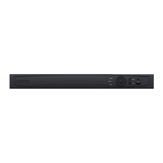
Digital Video Recorder Quick Start Guide Chapter1 Panels Description 1.1 Front Panel The front panel vaires according to different models. Please refer to the actual product. The following figures only take examples of several models. Front Panel 1 Figure 1-1 Front Panel 1 Table 1-1 Description of Front Panel 1 No. - Page 8 Digital Video Recorder Quick Start Guide No. Name Function Description Access the main menu interface Menu Exit and back to the previous menu. Receiver for IR remote controller. IR Receiver Universal Serial Bus (USB) ports for additional devices such as USB mouse and USB Hard Disk USB Interfaces Drive (HDD).
- Page 9 Digital Video Recorder Quick Start Guide Name Function Description Enters numeral “4”; 4/GHI/ESC Enters letters “GHI”; Exits and back to the previous menu. Enters numeral “5”; Enters letters “JKL”; Deletes characters before cursor; 5/JKL/EDIT Checks the checkbox and select the ON/OFF switch;...
- Page 10 Digital Video Recorder Quick Start Guide Name Function Description Cycles through channels in Live View mode. Controls the movement of the PTZ camera in PTZ control mode. Confirms selection in any of the menu modes. Checks the checkbox. Plays or pauses the playing of video files in ENTER Playback mode.
- Page 11 Digital Video Recorder Quick Start Guide Indicator turns green when DVR is controlled by an IR remote control with the address from 1~254; Indicator turns red when the SHIFT button is used; Indicator does not light when the DVR is controlled by a keyboard or by the IR remote control with the address of 255;...
- Page 12 Digital Video Recorder Quick Start Guide Switch of compound keys between the numeric/letter input SHIFT and functional control. Enter numeral “1”; 1/MENU Access the main menu interface. Enter numeral “2”; Enter letters “ABC”; The F1 button can be used to select all items on the list; 2ABC/F1 In PTZ Control mode, the F1 button can be used to zoom out (zoom-) the PTZ camera;...
- Page 13 Digital Video Recorder Quick Start Guide Enter numeral “9”; Enter letters “WXYZ”; 9WXYZ/PREV Multi-camera display in live view; In Playback mode or MenuPlaybackTag playback interface, this button can be used to delete the selected tag. Enter numeral “0”; Switch between input methods (upper and lowercase alphabet, symbols and numeric input).
- Page 14 Digital Video Recorder Quick Start Guide Name Function Description Indicator turns blue when the device is controlled by an IR remote. Indicator turns red when controlled by a keyboard and orange when IR remote and STATUS keyboard is used at the same time. Indicator does not light when the device is controlled by the IR remote control with the address of 255.
- Page 15 Digital Video Recorder Quick Start Guide Name Function Description In Auto-switch mode, it can be used to stop /start auto switch. Move the active selection in a menu. It will move the selection up and down. In Live View mode, it can be used to cycle through different channels.
- Page 16 Digital Video Recorder Quick Start Guide Name Function Description Switch between main and spot output. MAIN/SPOT/ In PTZ Control mode, it can be used to zoom out ZOOM- the image. Select all items on the list when used in a list field.
- Page 17 Digital Video Recorder Quick Start Guide Figure 1-5 Front Panel 5 Table 1-5 Description of Front Panel 4 and 5 Name Function Description POWER ON/OFF Power on/off switch. IR Receiver Receiver for IR remote ALARM Turns red when a sensor alarm is detected. Ready LED is normally blue, indicating that the READY device is functioning properly.
- Page 18 Digital Video Recorder Quick Start Guide Name Function Description In Live View mode, these buttons can be used to cycle through channels. In PTZ control mode, it can control the movement of the PTZ camera. The ENTER button is used to confirm selection in any of the menu modes.
- Page 19 Digital Video Recorder Quick Start Guide Name Function Description Enter/exit the folder of USB device and eSATA HDD. Switch between main and spot output. MAIN/SPOT/Z In PTZ Control mode, it can be used to zoom OOM- out the image. Select all items on the list when used in a list field.
-
Page 20: Rear Panel
Digital Video Recorder Quick Start Guide Name Function Description In the Playback mode: the ring is used to jump 30s forward/backward in video files. In PTZ control mode, it can control the movement of the PTZ camera. SLOW DOWN/SPEED UP Slow down/speed up in playback mode. - Page 21 Digital Video Recorder Quick Start Guide No. Item Function Description DB15 connector for VGA output. Display local video output and menu. AUDIO OUT RCA connector. Network Interface Connector for network Connector for RS-485 devices. T+ and T- pins connect to R+ and R- pins of PTZ receiver respectively.
- Page 22 Digital Video Recorder Quick Start Guide No. Item Function Description VIDEO OUT BNC connector for video output. AUDIO IN RCA connector USB Port Universal Serial Bus (USB) port for additional devices. HDMI1/VGA Simultaneous HDMI1/VGA output. Display local video output and menu. HDMI2 HDMI2 video output connector.
- Page 23 Digital Video Recorder Quick Start Guide Figure 1-8 Rear Panel 3 Table 1-8 Description of Rear Panel 3 No. Item Function Description VIDEO IN BNC interface for TVI and analog video input. AUDIO IN RCA connector AUDIO OUT RCA connector. DB15 connector for VGA output.
-
Page 24: Chapter 2 Installation And Connections
Digital Video Recorder Quick Start Guide Chapter 2 Installation and Connections 2.1 DVR Installation During installation of the DVR: Use brackets for rack mounting. Ensure ample room for audio and video cables. When routing cables, ensure that the bend radius of the cables are no less than five times than its diameter. - Page 25 Digital Video Recorder Quick Start Guide Figure 2-1 Fasten Hard Disk Step 2 Connect one end of the data cable to the motherboard of DVR and the other end to the HDD. Figure 2-2 Insert Panel Key Step 3 Connect the power cable to the HDD. Figure 2-3 Open Panel Lock Step 4 Place the HDD on the bottom of the device and then fasten the screws on the bottom to fix the HDD.
- Page 26 Digital Video Recorder Quick Start Guide Figure 2-4 Insert Hard Disk Step 5 Re-install the cover of the DVR and fasten screws. Type II Step 1 Remove the cover from the DVR by unfastening the screws on the back and side. Step 2 Install the HDD to the HDD rack using the provided screws, and then fasten the screws to fix the HDD.
- Page 27 Digital Video Recorder Quick Start Guide Step 2 Insert the key and turn in clockwise direction to open the panel lock. Step 3 Press the buttons on the two sides of the front panel to open it. Step 4 Insert the hard disk along the slot until it is placed into position. Step 5 Repeat the above steps to install other hard disks onto the DVR.
- Page 28 Digital Video Recorder Quick Start Guide...
-
Page 29: Rs-485 And Controller Connection
Digital Video Recorder Quick Start Guide 2.3 RS-485 and Controller Connection Typical Connection: Figure 2-5 Controller Connection A To connect PTZ to the DVR: Step 1 Disconnect pluggable block from the RS-485 terminal block. Step 2 Press and hold the orange part of the pluggable block; insert signal cables into slots and release the orange part. -
Page 30: Hdd Storage Calculation Chart
Digital Video Recorder Quick Start Guide 2.4 HDD Storage Calculation Chart The following chart shows an estimation of storage space used based on recording at one channel for an hour at a fixed bit rate. Bit Rate Storage Used 128K 160K 192K 224K... -
Page 31: Chapter 3 Menu Operation
Digital Video Recorder Quick Start Guide Chapter 3 Menu Operation 3.1 Menu Structure The menu structure varies according to different models. Menu Playback Maintenance Shutdown Export VCA Search Record Camera Configuration Manual Behavior Normal Normal Schedule Camera General System Info Logout Record General... -
Page 32: Activating Your Device
Digital Video Recorder Quick Start Guide Step 2 Press the POWER button on the front panel. The Power LED should turn blue. The unit will begin to start. After the device starts up, the wizard will guide you through the initial settings, including modifying password, date and time settings, network settings, HDD initializing, and recording. - Page 33 Digital Video Recorder Quick Start Guide STRONG PASSWORD RECOMMENDED–We highly recommend you create a strong password of your own choosing (Using a minimum of 8 characters, including at least three of the following categories: upper case letters, lower case letters, numbers, and special characters.) in order to increase the security of your product.
-
Page 34: Using The Unlock Pattern For Login
Digital Video Recorder Quick Start Guide Figure 3-6 Export GUID Step 5 After exporting GUID, the Attention box pops up as below. Click Yes to duplicate the password or No to cancel it. Figure 3-7 Duplicate the Password 3.4 Using the Unlock Pattern for Login For the Admin user, you can configure the unlock pattern for device login. -
Page 35: Login And Logout
Digital Video Recorder Quick Start Guide Connect at least 4 dots to draw the pattern. Each dot can be connected for once only. Step 2 Draw the same pattern again to confirm it. When the two patterns match, the pattern is configured successfully. - Page 36 Digital Video Recorder Quick Start Guide Step 3 Click OK to log in. Clear-text password is supported. Click the icon and you can see the clear text of the password. Click the icon again and the content of the password restores invisible. ...
-
Page 37: User Logout
Digital Video Recorder Quick Start Guide Figure 3-14 Reset Password 2) Input the new password and confirm the password. 3) Click OK to save the new password. Then the Attention box pops up as shown below. Figure 3-15 GUID File Imported 4) Click OK and the Attention box as below pops up to remind you to duplicate the password of the device to IP cameras that are connected with default protocol. -
Page 38: Configuring The Signal Input
Digital Video Recorder Quick Start Guide Menu > Shutdown Figure 3-17 Logout Step 2 Click Logout. After you have logged out the system, menu operation on the screen is invalid. It is required to input a user name and password to unlock the system. 3.6 Configuring the Signal Input Purpose For certain series DVR, you should configure the analog and IP signal input types. -
Page 39: Using The Setup Wizard
Digital Video Recorder Quick Start Guide Four kinds of analog signal inputs including HDTVI (including 3 MP, 1080p and 720p signal), AHD, HDCVI and CVBS can be connected. The analog signal inputs can be recognized automatically and can be mixed randomly. ... -
Page 40: Adding Ip Cameras
Digital Video Recorder Quick Start Guide Figure 3-20 Network Settings Step 2 Select the General tab. Step 3 In the General Settings interface, you can configure the following settings: Working Mode (applicable for certain series only), NIC Type, IPv4 Address, IPv4 Gateway, MTU and DNS Server. - Page 41 Digital Video Recorder Quick Start Guide Figure 3-21 Add IP Camera Step 2 Select the IP camera from the list and click the button to add the camera (with the same admin password of the DVR’s). Step 3 (Optional) Check the checkbox of Enable H.265 (For Initial Access) for the connected IP camera supporting H.265.
-
Page 42: Live View
Digital Video Recorder Quick Start Guide 3.10 Live View Icons are provided on screen in Live View mode to indicate camera status. These icons include: Live View Icons In the live view mode, there are icons at the upper-right corner of the screen for each channel, showing the status of the record and alarm in the channel for quick reference. -
Page 43: Playback
Digital Video Recorder Quick Start Guide Step 2 Click the Yes button in the pop-up Attention message box to confirm the settings. All the channels will start to record in the selected mode. 3.12 Playback The recorded video files and pictures on the hard disk can be played back in the following modes: instant playback, all-day playback for the specified channel, and playback by normal/event/smart/tag/system logs/sub-periods/external file search/picture. -
Page 44: Chapter 4 Accessing By Web Browser
Digital Video Recorder Quick Start Guide Chapter 4 Accessing by Web Browser You shall acknowledge that the use of the product with Internet access might be under network security risks. For avoidance of any network attacks and information leakage, please strengthen your own protection. - Page 45 Digital Video Recorder Quick Start Guide If the device is already activated, enter the user name and password in the login interface, and click the Login button. Figure 4-2 Login Step 3 Install the plug-in before viewing the live video and managing the camera. Please follow the installation prompts to install the plug-in.
Need help?
Do you have a question about the HHR315-16 and is the answer not in the manual?
Questions and answers