5.3 Positioning 5.4 Electrical connection 5.5 Instructions for the installer ORIGINAL INSTRUCTIONS We advise you to read this manual carefully, as it contains all the instructions for maintaining the appliance’s aesthetic and functional qualities. For further information on the product: www.smeg.com...
Instructions 1 Instructions • Children must not play with the appliance. 1.1 General safety instructions • Keep children under the age of Risk of personal injury 8 at a safe distance unless they are constantly supervised. • During use the appliance and its •...
Page 3
Instructions • Fats and oils can catch fire if • Do not open the storage they overheat. Do not leave the compartment (where present) appliance unattended while when the oven is on and still hot. preparing foods containing oils • The items inside the storage or fats.
Page 4
Instructions • Before performing any • Do not sit on the appliance. operation on the appliance, • Racks and trays should be switch off the power supply. inserted as far as they will go • Have qualified personnel carry into the side guides. The out installation and assistance mechanical safety locks that interventions according to the...
Page 5
Instructions • Do not cover the bottom of the • Do not put empty pans or frying oven cavity with aluminium or tin pans on switched on cooking foil sheets. zones. • Do not place pans or trays • Do not use rough or abrasive directly on the bottom of the materials or sharp metal oven cavity.
Page 6
Instructions Installation • The adjustment conditions for this appliance are shown on • THIS APPLIANCE MUST NOT the gas setting label. BE INSTALLED IN A BOAT OR • Have the gas connection CARAVAN. performed by authorised staff. • This appliance must not be •...
Instructions • Have the electrical connection 1.2 Manufacturer liability performed by authorised The manufacturer declines all technicians. liability for damage to persons or • The appliance must be property caused by: connected to ground in • use of the appliance other than compliance with electrical that specified;...
Instructions 1.4 Identification plate 1.6 Disposal The identification plate bears the This appliance must be technical data, serial number and disposed of separately from brand name of the appliance. Do not other waste (Directives remove the identification plate for 2002/95/EC, 2002/96/EC, any reason.
Instructions • Deliver the appliance to the 1.7 How to read the user manual appropriate recycling centre for This user manual uses the following reading electrical and electronic conventions: equipment waste, or return it to Instructions the retailer when purchasing an General information on this user equivalent product, on a one for manual, on safety and final...
Description 2 Description 2.1 General Description 1 Upstand 7 Main oven fan 2 Cooking hob 8 Auxiliary oven light 3 Control panel 9 Auxiliary oven seal 4 Main oven light 10 Auxiliary oven door 5 Main oven seal 11 Storage compartment 6 Main oven door Rack/tray support frames...
Description 2.3 Control panel 1 Minute minder timer knob 5 Auxiliary oven temperature/function knob In order to use the minute minder timer, the buzzer must be set by turning the knob It turns on the light inside the oven or starts clockwise.
Description 2.4 Other parts Interior lighting The appliance’s interior lighting comes on: Shelves (main oven) The appliance features shelves to position • when the door is opened; trays and racks at different heights. The • when any function is selected, apart from insertion heights are indicated from the bottom upwards (see 2.1 General function.
Description 2.5 Available accessories Deep tray Not all accessories are available on some models. The oven accessories intended to come into contact with food are made of materials that comply with the provisions of current legislation. Original supplied and optional accessories can be requested to Authorised Assistance Centres.
Page 15
Description Tray rack Rack To be placed over the top of the tray; for Useful for supporting containers with food cooking foods which may drip. during cooking.
3 Use High temperature inside the storage compartment High temperature inside the oven Danger of burns during use Danger of burns • Do not open the storage compartment when the appliance is on and still hot. • Keep the oven door closed during •...
Page 17
Malfunctions High temperature inside the storage compartment Any of the following indicate a malfunction and you should contact a service centre: Danger of fire or explosion • Yellowing of the burner plate. • Do not spray any spray product near the •...
3.1 To save energy 3.2 Using the accessories • Preheat the appliance only if the recipe Ring reducers requires it. The ring reducers must be placed on the • Unless differently stated on the package, hob grids. Make sure they are placed defrost frozen food before placing it in properly.
3.3 Using the hob Racks and trays All the appliance’s control and monitoring Racks and trays have to be inserted into the devices are located together on the front side guides until they come to a complete panel. The burner controlled by each knob stop.
Correct positioning of the flame-spreader Practical tips for using the hob crowns and burner caps For better burner efficiency and to minimise Before lighting the hob burners, make sure that gas consumption, use pans with lids and of the flame-spreader crowns are correctly suitable size for the burner, so that the positioned in their seats with their respective flames do not reach up the sides of the pan.
3.5 Using the ovens Switching on the main oven Fan + lower element The combination of the fan with just the lower heating element allows cooking to be completed more 1. Select manual cooking or set the rapidly. This system is recommended cooking duration using the timer knob.
Page 22
Fan with round heating element When using the ECO function, avoid opening the door during The combination of the fan and the cooking. round heating element (incorporated in the rear of the oven) allows you to cook different Cooking (and preheating) times foods on several levels, as long as are longer with the ECO function.
Page 23
Switching on the auxiliary oven Lower heating element (245 °C) The heat coming just from the bottom allows you to complete the Turn the temperature/function knob to the cooking of foods that require a required temperature, from a minimum of higher bottom temperature, without 50°C to a maximum of 245°C, or to the required function (at the maximum...
Page 24
General advice • When using the Fan with grill function, we recommend that you preheat the • Use a fan assisted function to achieve oven before grilling. consistent cooking at several levels. • We recommend placing the food at the •...
Page 25
Advice for defrosting and proving • Place frozen foods without their packaging in a lidless container on the first shelf of the oven. • Avoid overlapping the food. • To defrost meat, use the rack placed on the second level and a tray on the first level.
Page 26
Main oven cooking information table Weight Temperature Food Function Shelf Time (minutes) (kg) (°C) Lasagne 3 - 4 Static 220 - 230 45 - 50 Pasta bake 3 - 4 Static 220 - 230 45 - 50 Roasted veal Turbo/Round 180 - 190 90 - 100 Pork loin...
Cleaning and maintenance 4 Cleaning and maintenance Ordinary daily cleaning Always use specific products only that do Improper use not contain abrasives or chlorine-based Risk of damage to surfaces acids. Pour the product onto a damp cloth and • Do not use steam jets to clean the wipe the surface, rinse thoroughly and dry appliance.
Cleaning and maintenance 4.2 Cleaning the hob Igniters and thermocouples For correct operation the igniters and Cooking hob grids thermocouples must always be perfectly Remove the grids and clean them in clean. Check them frequently and clean lukewarm water and non-abrasive them with a damp cloth if necessary.
Cleaning and maintenance 4.3 Cleaning the door 3. To reassemble the door, put the hinges in the relevant slots in the oven, making sure Removing the door that grooved sections A are resting For easier cleaning, the door can be completely in the slots.
Page 31
Cleaning and maintenance Removing the internal glass panes 4. Clean the external glass pane and the previously removed panes. Use For easier cleaning, the internal glass panes absorbent kitchen roll. In case of of the door can be removed. stubborn dirt, wash with a damp sponge 1.
Cleaning and maintenance 4.4 Cleaning the oven cavities Removing racks/trays support frames For the best oven cavities upkeep, clean Removing the guide frames enables them regularly after having allowed them to the sides to be cleaned more easily. cool. This operation should be performed each time the automatic cleaning cycle is used Avoid letting food residue dry inside the (on some models only).
Cleaning and maintenance 4.5 Vapour Clean Vapor Clean is an assisted cleaning procedure which facilitates the removal of dirt. Thanks to this process, it is possible to clean the inside of the main oven very easily. The dirt residues are softened by the heat and water vapour for easier removal afterwards.
Page 34
Cleaning and maintenance Vapor Clean cycle setting For improved hygiene and to avoid food being affected by any unpleasant odours, 1. Turn the function knob to the symbol we recommend that the oven is dried using a fan assisted function at 160 °C for and the temperature knob to the symbol approximately 10 minutes.
Cleaning and maintenance 4.6 Extraordinary maintenance 4. Slide out and remove the light bulb. Replacing the interior light bulb (main oven) Live parts Danger of electrocution • Unplug the appliance from the mains. 1. Remove all accessories from inside the oven cavity.
Page 36
Cleaning and maintenance Replacing the interior light bulb Installing and removing the oven seal (auxiliary oven) (pyrolitic oven excluded) 1. Unscrew bulb protector A (turn anti- To remove the seal: clockwise). • Unhook the clips in the 4 corners then pull the seal outwards.
Installation 5 Installation Connection with a rubber hose Verify that all following conditions are met: 5.1 Gas connection • the hose is attached to the hose connector with safety clamps; Gas leak • no part of the hose is in contact with hot Danger of explosion walls (max.
Page 38
Installation Carefully screw the hose connector 3 to the Connection with a steel hose appliance’s gas connector 1 (½” thread Make the connection to the gas mains ISO 228-1), placing the seal 2 between using a continuous wall steel hose whose them.
Page 39
Installation Connection to LPG Room ventilation Use a pressure regulator and make the The appliance should be installed in rooms connection on the gas cylinder following that have a permanent air supply in the guidelines set out in the standards in accordance with the standards in force.
Installation An efficient extraction system requires 5.2 Adaptation to different types of precision planning by a specialist qualified in this area and must comply with the The appliance is preset for natural positions and clearances indicated by the gas G20 at a pressure of applicable standards.
Page 41
Installation 1. Internal nozzle Adjusting the minimum setting for LPG 2. External nozzle Tighten the screw located at the side of the 3. Reposition the burners in their respective cock rod clockwise all the way. housings. Following adjustment to a gas Adjusting the minimum setting for natural other than the one originally set in or town gas...
Page 42
Installation Gas types and Countries Gas types IT GB-IE FR-BE DE AT NL ES PT SE RU DK PL HU 1 Natural gas G20 • • • • • • • • • 20 mbar • G20/25 20/25 mbar 2 Natural gas G20 •...
Installation 5.3 Positioning Any wall units positioned above the worktop of the appliance must be at a Heavy appliance minimum distance of at least Y mm. If a Crushing hazard hood is installed above the hob, refer to the hood instruction manual to ensure the correct clearance is left.
Page 46
Installation Appliance overall dimensions 900 mm 600 mm B - Class 2 subclass 1 min. 150 mm (Built-in appliance) 900 - 915 mm 750 mm 450 mm 900 mm Minimum distance from side walls or other flammable material. Minimum cabinet width (=A). C - Class 2 subclass 1 (Built-in appliance) The appliance must be installed by...
Page 47
Installation Dimensions of the appliance: locations of Positioning and levelling gas and electric connections (mm) Heavy appliance Risk of damage to the appliance • Insert the front feet first and then the rear ones. After making the electrical and/or gas connections, screw the four adjustable feet supplied with the appliance.
Page 48
Installation 3. Assemble the fastening bracket. Fastening to the wall The anti-tip devices must be installed in order to prevent the appliance from tipping over. 1. Screw the wall fastening plate to the rear of the appliance. 4. Align the base of the hook on the fastening bracket with the base of the slot on the wall fastening plate.
Page 49
Installation 5. Align the base of the fastening bracket 7. Move the bracket onto the wall and with the ground and tighten the screws to mark the position of the holes to be fix the measurements. drilled in the wall. 8.
Installation 5.4 Electrical connection Assembling the upstand The upstand provided is an Power voltage integral part of the product; it must Danger of electrocution be fastened to the appliance prior to installation. • Have the electrical connection performed by authorised technicians. The upstand must always be positioned and •...
Page 51
Installation The appliance can work in the following modes: The values indicated above refer • 220-240 V 1N~ to the cross-section of the internal lead. The aforementioned power cables are sized taking into account the 3 x 2.5 mm² three-core cable. coincidence factor (in compliance with standard EN 60335-2-6).
Installation 5.5 Instructions for the installer • The plug must be accessible after installation. Do not bend or trap the power cable. • The appliance must be installed according to the installation diagrams. • Do not try to unscrew or force the threaded elbow of the fitting.
Need help?
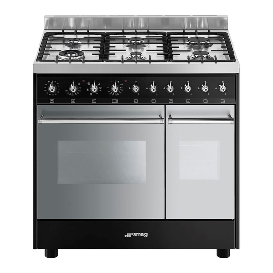
Do you have a question about the C92DBL9 and is the answer not in the manual?
Questions and answers