Table of Contents
Advertisement
Quick Links
We advise you to read this manual carefully, which contains all the instructions for
maintaining the appliance's aesthetic and functional qualities.
For further information on the product: www.smeg.com
Contents
48
48
49
49
49
50
50
50
51
51
52
52
53
54
55
55
56
56
59
60
62
62
64
69
69
69
70
71
71
73
75
77
77
80
85
89
47
Advertisement
Table of Contents

Related Manuals for Smeg C9GMN9


Summary of Contents for Smeg C9GMN9
-
Page 1: Table Of Contents
5.2 Adaptation to different types of gas 5.3 Positioning 5.4 Electrical connection We advise you to read this manual carefully, which contains all the instructions for maintaining the appliance’s aesthetic and functional qualities. For further information on the product: www.smeg.com... -
Page 2: Instructions
Instructions 1 Instructions • Do not insert pointed metal objects (cutlery or utensils) into the 1.1 General safety instructions slots in the appliance. • Do not try to repair the appliance Risk of personal injury yourself or without the intervention •... -
Page 3: Manufacturer Liability
Instructions 1.4 Disposal For this appliance This appliance must be disposed of • Ensure that the appliance is switched off separately from other waste before replacing the bulb. (Directives 2002/95/EC, 2002/ • Do not rest any weight or sit on the open 96/EC, 2003/108/EC). -
Page 4: Identification Plate
Instructions Our appliances are packaged in non- 1.7 How to read the user manual polluting and recyclable materials. This user manual uses the following reading • Deliver the packing materials to the conventions: appropriate recycling centre. Instructions Plastic packaging General information on this user Danger of suffocation manual, on safety and final disposal. -
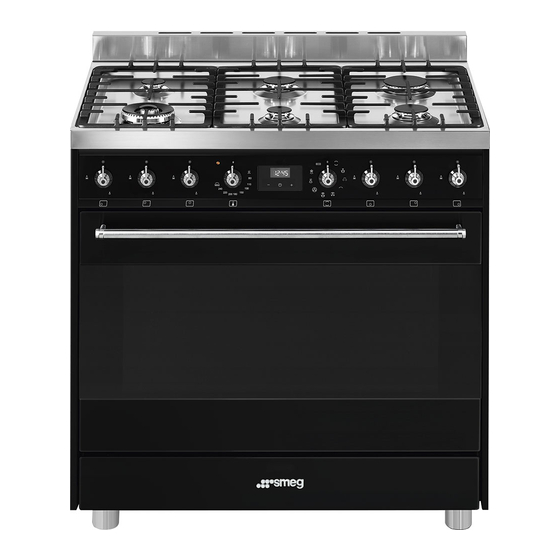
Page 5: Description
Description 2 Description 2.1 General Description 1 Upstand 6 Door 2 Cooking hob 7 Fan 3 Control panel 8 Storage compartment 4 Oven light Rack/tray support frame shelf 5 Seal... -
Page 6: Cooking Hob
Description 2.2 Cooking hob AUX = Auxiliary R = Rapid SR = Semi-rapid UR = Ultra rapid 2.3 Control panel 1 Hob burner knobs Return the knobs to the position to turn Useful for lighting and adjusting the hob off the burners. burners. -
Page 7: Other Parts
Description 3 Temperature knob Cooling fan This knob allows you to select the cooking The fan cools the oven and comes into temperature. operation during cooking. Turn the knob clockwise to the required The fan causes a steady outflow of air that value, between the minimum and maximum exits from the rear of the appliance and setting. -
Page 8: Available Accessories
Description 2.5 Available accessories Deep tray Some models are not provided with all accessories. Ring reducers Useful for collecting fat from foods placed on the rack above. Rotisserie Useful when using small cookware. WOK ring Useful when using a wok. Useful for cooking chicken and all foods which require uniform cooking over their Rack... -
Page 9: Use
3 Use Improper use Risk of damage to surfaces 3.1 Instructions High temperature inside the oven • Do not cover the bottom of the oven during use cavity with aluminium or tin foil sheets. Danger of burns • If you wish to use greaseproof paper, place it so that it will not interfere with the •... -
Page 10: First Use
3.3 Using the accessories High temperature inside the oven during use Ring reducers Danger of fire or explosion The ring reducers have to be placed on the hob grids. Make sure they are placed • Do not spray any spray products near properly. - Page 11 Racks and trays Rotisserie Racks and trays have to be inserted into the 1. Insert the 4 supplied bushings in the 4 side guides until they come to a complete corner holes of the deep tray and screw stop. them onto the ring nuts with a suitable tool (such as a screwdriver).
- Page 12 3. Prepare the rotisserie rod with the food 5. Place the tray on the first runner (see using the clip forks provided. The clip “General Description”). forks can be tightened using the 6. Insert the tip of the rod in the rotisserie fastening screws.
-
Page 13: Using The Hob
3.4 Using the hob 8. When cooking is complete, remove the tray with the rotisserie. All the appliance’s control and monitoring devices are located together on the front 9. Screw on the handle provided so that panel. The burner controlled by each knob you can handle the rotisserie rod more is shown next to the knob. -
Page 14: Using The Oven
Correct positioning of the flame- 3.5 Using the oven spreader crowns and burner caps Switching on the oven Before lighting the hob burners, make sure To switch on the oven: that the flame-spreader crowns are 1. Select the cooking function using the correctly positioned in their housings with function knob. - Page 15 Fan + lower element Fan assisted The combination of the fan with just The operation of the fan, combined the lower heating element allows with traditional cooking, ensures cooking to be completed more consistent cooking even with rapidly. This system is complex recipes.
-
Page 16: Using The Storage Compartment
3.7 Cooking advice Rapid defrost Rapid defrost is helped by the General advice activation of a fan to ensure uniform • Use a fan assisted function to achieve distribution of room temperature air consistent cooking at several levels. inside the oven. Perfect for any type •... - Page 17 • Foods should be seasoned before Advice for defrosting and proving cooking. Foods should also be coated • Place frozen foods without their with oil or melted butter before cooking. packaging in a lidless container on the • Use the oven tray on the first bottom shelf first shelf of the oven.
-
Page 18: Programmer Clock
3.8 Programmer clock Setting the time If the time is not set, the oven will not switch on. On the first use, or after a power failure, the digits will be flashing on the appliance’s display. 1. Hold down the clock key for two seconds. - Page 19 Timed cooking 6. Press the clock key to reset the programmer clock. Timed cooking is the function which allows a cooking operation It is not possible to set a cooking to be started and then ended after time of more than 10 hours. a specific length of time set by the user.
- Page 20 10. Return the function and temperature 4. Use the key to set the knobs to 0. required minutes (for example 1 hour) 11. To turn off the buzzer just press any key 5. Press the menu key . The text of the programmer clock.
- Page 21 Modifying the set data Minute minder timer 1. Press the clock key The minute minder timer does not stop the cooking operation but 2. Use the value increase and value rather informs the user when the set time has run out. decrease keys to set the number of minutes required.
- Page 22 Cooking information table Runner Weight Temperature Food Function position from Time (minutes) (Kg) (°C) the bottom Lasagne 3 - 4 Static 220 - 230 45 - 50 Pasta bake 3 - 4 Static 220 - 230 45 - 50 Roasted veal Turbo/Fan assisted 180 - 190 90 - 100...
-
Page 23: Cleaning And Maintenance
Cleaning and maintenance 4 Cleaning and maintenance Cleaning the hob 1. Pour some non-abrasive detergent on a 4.1 Instructions damp cloth and wipe the surfaces. 2. Rinse thoroughly. Improper use Risk of damage to surfaces 3. Dry with a soft cloth or a microfibre cloth. Cleaning the hob grids, flame-spreader •... -
Page 24: Removing The Door
Cleaning and maintenance Cleaning the igniters and thermocouples For easier cleaning, we recommend removing: • If necessary, clean the igniters and • The door; thermocouples with a damp cloth. • The rack/tray support frames; • If there is any dry residue, remove it with a toothpick or needle. -
Page 25: Cleaning The Door Glazing
Cleaning and maintenance 4.5 Removing the internal glass 2. Grasp the door on both sides with both hands, lift it forming an angle of around panes 30° and remove it. For easier cleaning the internal glass panes of the door can be removed. 1. - Page 26 Cleaning and maintenance 4. Clean the external glass pane and the Removing racks/trays support frames panes removed previously. Use Removing the rack/tray support frames absorbent kitchen roll. In case of enables the sides to be cleaned more stubborn dirt, wash with a damp sponge easily.
-
Page 27: Vapor Clean
Cleaning and maintenance 4.6 Vapor Clean • Pour approximately 40 cc of water into the tray. Make sure it does not overflow Vapor Clean is an assisted out of the cavity. cleaning procedure which facilitates the removal of dirt. Thanks to this process, it is possible to clean the inside of the oven very easily. - Page 28 Cleaning and maintenance Vapor Clean cycle setting End of the Vapor Clean cycle 1. Set a cooking time of 18 minutes using 4. Open the door and wipe away the less the programmer clock. stubborn dirt with a microfibre cloth. 5.
-
Page 29: Extraordinary Maintenance
Cleaning and maintenance 4.7 Extraordinary maintenance 4. Slide out and remove the light bulb. Replacing the internal light bulb Live parts Danger of electrocution • Unplug the appliance. The oven is fitted with a 40W light Do not touch the halogen light bulb. - Page 30 Cleaning and maintenance Installing and removing the seal To remove the seal: • Unhook the clips located in the 4 corners and in the centre, then pull the seal outwards. To refit the seal: • Hook the clips located in the 4 corners and in the centre onto the seal.
-
Page 31: Installation
Installation 5 Installation Connection with a rubber hose Verify that all following conditions are met: 5.1 Gas connection • the hose is fixed to the hose connection with safety clamps; Gas leak • no part of the hose is in contact with hot Danger of explosion walls (max. - Page 32 Installation After having tightened the hose Carefully screw the connector 3 to the gas connector(s), push the gas hose 6 onto the connector 1 of the appliance, placing the hose connector and secure it with the clamp 5 seal 2 between them. that is compliant with the standard in force.
- Page 33 Installation Connection with a steel hose with conical Room ventilation fitting The appliance should be installed in rooms Make the connection to the gas mains that have a permanent air supply in using a continuous wall steel hose whose accordance with the standards in force. The specifications comply with the applicable room where the appliance is installed must standard.
-
Page 34: Adaptation To Different Types Of Gas
Installation When the job is complete, the installer must 5.2 Adaptation to different types of issue a certificate of conformity. In case of operation with other types of gas, the burner nozzles must be changed and the minimum flame adjusted on the gas cocks. - Page 35 Installation Adjusting the minimum setting for natural Adjusting the minimum setting for LPG or town gas Tighten the screw located at the side of the Light the burner and turn it to the minimum tap rod clockwise all the way. position.
- Page 36 Installation Gas types and Countries Gas types IT GB-IE FR-BE DE RU DK 1 Natural Gas G20 • • • • • • • • • 20 mbar G20/25 20/25 mbar • 2 Natural Gas G20 25 mbar • 3 Natural Gas G25 25 mbar •...
- Page 37 Installation Burner and nozzle characteristics tables 1 Natural Gas G20 UR2 (int+ext) Rated heating capacity (kW) Nozzle diameter (1/100 mm) 75+135 Pre-chamber (printed on nozzle) (H9) (H1)+(H3) Reduced flow rate (W) 1900 2 Natural Gas G20 UR2 (int+ext) Rated heating capacity (kW) Nozzle diameter (1/100 mm) 75+127 Pre-chamber (printed on nozzle)
- Page 38 Installation 8 LPG G30/31 UR2 (int+ext) Rated heating capacity (kW) 1.75 Nozzle diameter (1/100 mm) 46+91 Pre-chamber (printed on nozzle) Reduced flow rate (W) 1900 Rated flow rate G30 (g/h) Rated flow rate G31 (g/h) 9 LPG G30/31 UR2 (int+ext) Rated heating capacity (kW) Nozzle diameter (1/100 mm) 46+85...
-
Page 39: Positioning
Installation 5.3 Positioning General information This appliance may be installed next to Heavy appliance walls, one of which must be higher than the Crushing hazard worktop, at a minimum distance of 50 mm from the side of the appliance, as shown in •... - Page 40 Installation Positioning and levelling Heavy appliance Risk of damage to the appliance • Insert the front feet first and then the rear ones. • After making the gas and electrical connections, screw on the four feet supplied with the appliance. B - Class 2 subclass 1 (Built-in appliance) The appliance must sit level on the floor to...
- Page 41 Installation 3. Assemble the fastening bracket. Fastening to the wall The anti-tip devices must be installed in order to prevent the appliance from tipping over. 1. Screw the wall fastening plate to the rear of the appliance. 4. Align the base of the hook on the fastening bracket with the base of the slot on the wall fastening plate.
- Page 42 Installation 5. Align the base of the fastening bracket 7. Move the bracket onto the wall and with the ground and tighten the screws to mark the position of the holes to be fix the measurements. drilled in the wall. 6.
-
Page 43: Electrical Connection
Installation 5.4 Electrical connection Assembling the upstand The upstand provided is an Power voltage integral part of the product. It must Danger of electrocution be fastened to the appliance prior to installation. • Have the electrical connection performed by authorised technical The upstand must always be positioned and personnel. - Page 44 Installation The appliance can work in the following modes: • 220-240 V 1N~ 3 x 1.5 mm² three-core cable. The values indicated above refer to the cross-section of the internal conductor. The aforementioned power cables are sized taking into account the coincidence factor (in compliance with standard EN 60335-2-6).
Need help?
Do you have a question about the C9GMN9 and is the answer not in the manual?
Questions and answers