Table of Contents
Advertisement
Quick Links
Advertisement
Chapters
Table of Contents

Related Manuals for KNF N1200


Summary of Contents for KNF N1200
- Page 1 KNF 308926-308929 02/22 N1200, N1400.1.2 TRANSLATION OF ORIGINAL OPERATING AND INSTALLATION INSTRUCTION ENGLISH DIAPHRAGM PUMP Notice! Before operating the pump and accessories, read and observe the operating and installation instructions as well as the safety information!
-
Page 2: Table Of Contents
Index KNF Neuberger GmbH Alter Weg 3 1 About this document ............ 3 79112 Freiburg 1.1 Using the operating and installation instructions.. 3 Germany 1.2 Exclusion of liability........... 3 Tel. +49 (0)7664/5909-0 1.3 Symbols and markings.......... 4 Fax. +49 (0)7664/5909-99 2 Safety................ 6 2.1 Personnel and target group ........ 6... -
Page 3: About This Document
à In the event of uncertainties with regard to the content of the operating and installation instructions, please contact the manufacturer (contact data: see www.knf.com). Please have the type and serial number of the pump ready. à The individual chapters of these operating and installation instructions make reference to the operating instructions of the motor manufacturer for capacitor and three-phase motors. -
Page 4: Symbols And Markings
An activity to be carried out is specified here (a step). 1. The first step of an activity to be carried out is specified here. Follow other sequentially numbered steps. This symbol indicates important information. Translation of Original operating and installation instruction, English, KNF 308926-308929 02/22... - Page 5 Warning of electrical voltage Warning of poisonous substances Warning of hand injuries through crushing Observe the operating instructions General mandatory sign Wear hearing protection Environmentally conscious disposal Tab.2 Explanations of pictograms Translation of Original operating and installation instruction, English, KNF 308926-308929 02/22...
-
Page 6: Safety
Operating Only operate and install the pump under the operating parameters and op- parameters erating conditions described in Chapters 2.4 Operating conditions and 3 Technical data. Translation of Original operating and installation instruction, English, KNF 308926-308929 02/22... -
Page 7: Working In A Safety Conscious Manner
Make sure that a dangerous situation cannot arise as a result. When pumping hazardous media, observe the safety regulations for the handling of said media. Handling of combustible media Note that the pump is not designed to be explosion-proof. Translation of Original operating and installation instruction, English, KNF 308926-308929 02/22... -
Page 8: Use
This function can be made possible on a project basis following consulta- tion with KNF Customer Service. Pumps with capacitor motor are not intended for operation with a fre- quency converter. Translation of Original operating and installation instruction, English, KNF 308926-308929 02/22... -
Page 9: Directives And Standards
EN 60204-1 2.8 Customer service and repair Customer service and repairs The pump is maintenance-free. However, KNF recommends periodic in- spection of the pump for obvious changes in noise or vibration. Only have repairs to the pumps performed by qualified KNF personnel. -
Page 10: Technical Data
Tab.7 *Bar rel related to 1013 hPa **Liters in standard state (1013 hPa, 20°C) Pneumatic connections Pump type Value N1200 Thread size G 1/2* N1400.1.2 For hose Ø 18 Tab.8 *Acc. to ISO 228 Translation of Original operating and installation instruction, English, KNF 308926-308929 02/22... - Page 11 See operating instructions for motor voltage fluctuations Tab.11 *For further voltage and frequency variants, see type plate **See type plate Weight Pump type Weight [kg] N1200 approx. 57 N1400.1.2 approx. 76.5 Tab.12 Translation of Original operating and installation instruction, English, KNF 308926-308929 02/22...
- Page 12 A leak test can be used to determine whether the original gas tightness is again achieved. ***Values apply for helium leak test Translation of Original operating and installation instruction, English, KNF 308926-308929 02/22...
-
Page 13: Product Description And Function
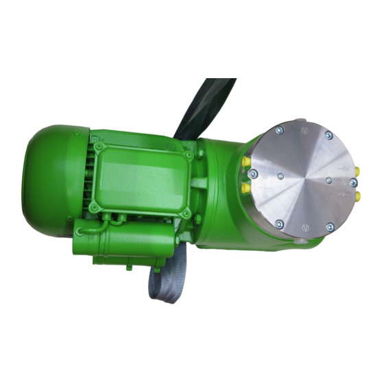
2 Connection for water cool- 3 Pneumatic head connec- tion 4 Pneumatic pump inlet 5 Motor 6 Motor fan cover 7 Electrical terminal box 8 Pneumatic pump outlet Fig.2 Diaphragm pump N1400.1.2 Translation of Original operating and installation instruction, English, KNF 308926-308929 02/22... - Page 14 (2). In the upwards stroke, the diaphragm presses the medium out of the pump head via the outlet valve (1). The transfer chamber (3) is separated from the pump drive by the diaphragm. Translation of Original operating and installation instruction, English, KNF 308926-308929 02/22...
-
Page 15: Transport
Storage temperature [°C] + 5 to + 40 Transport temperature [°C] - 10 to + 60 Permissible humidity (non-condens- 30 to 85 ing) [%] Tab.14 Transport parameter and storage parameter Translation of Original operating and installation instruction, English, KNF 308926-308929 02/22... -
Page 16: Transport With Carrying Strap
(3 Techni- cal data). NOTICE Transport with carrying strap Fig.4 Position of carrying strap (example) 1. Pull the carrying strap under the pump (see Fig. 4). Fig.5 Translation of Original operating and installation instruction, English, KNF 308926-308929 02/22... - Page 17 3. Make certain that the lifting load cannot be transferred from the belt to the pump connection. 4. Lift the pump from the packaging with the help of lifting gear. 5. Lower the pump carefully at the installation location. Translation of Original operating and installation instruction, English, KNF 308926-308929 02/22...
-
Page 18: Installation And Connection
Store the pump at the installation site to allow it to adapt to the ambient temperature before installation (condensation must not be allowed to form). à Mounting dimensions For mounting dimensions, see the following figures: Fig.6 Mounting dimensions pump series N1200 Translation of Original operating and installation instruction, English, KNF 308926-308929 02/22... - Page 19 Chapter 3 Technical data). à Make sure that access to moving parts is prevented. The IP protection class of the pump motor is specified on the type plate. Translation of Original operating and installation instruction, English, KNF 308926-308929 02/22...
-
Page 20: Electrical Connection
– the cables cannot be worn or damaged on sharp corners or edges – no tensile and pressure forces are exerted on the connection point of the cables (strain relief) Translation of Original operating and installation instruction, English, KNF 308926-308929 02/22... -
Page 21: Pneumatic Connection
In this way it is possible to prevent the transfer of possible pump vibrations and noises to the system. Translation of Original operating and installation instruction, English, KNF 308926-308929 02/22... -
Page 22: Connecting Water Cooling (Optional)
The flow direction is allowed in both directions. Mounting dimensions For mounting dimensions, see the following dimensional drawings: The base plate is shown as an additional accessory on the following dimensional drawings. Translation of Original operating and installation instruction, English, KNF 308926-308929 02/22... - Page 23 Diaphragm Pump N1200, N1400.1.2 Installation and connection Fig.8 Mounting dimensions pump series N1200 Translation of Original operating and installation instruction, English, KNF 308926-308929 02/22...
- Page 24 Installation and connection Diaphragm Pump N1200, N1400.1.2 Fig.9 Mounting dimensions pump series N1400.1.2 Translation of Original operating and installation instruction, English, KNF 308926-308929 02/22...
-
Page 25: Operation
à Ensure that the pump outlet is not closed or restricted. Translation of Original operating and installation instruction, English, KNF 308926-308929 02/22... -
Page 26: Information On Switching The Pump On And Off
PTC thermistor sensors and switching off the pump. à Ensure that normal atmospheric pressure is present in the lines when switching on. Translation of Original operating and installation instruction, English, KNF 308926-308929 02/22... - Page 27 à Before recommissioning, observe the applicable standards, guidelines, regulations and technical standards at the electrical connection. à Inspecting the pump Inspect the pump periodically for external damage or leakage. Translation of Original operating and installation instruction, English, KNF 308926-308929 02/22...
-
Page 28: Servicing
(if necessary for safety reasons: with an inert gas) to extend the service life of the diaphragm. à Discharge the media safely. Translation of Original operating and installation instruction, English, KNF 308926-308929 02/22... -
Page 29: Changing Diaphragm And Reed Valves
Depending on the medium being transferred, caustic burns or poisoning is possible. WARNING à Wear protective equipment if necessary, e.g., protective gloves, goggles. à Clean the pump with suitable measures. Translation of Original operating and installation instruction, English, KNF 308926-308929 02/22... - Page 30 KNF accessory, see 10.2 Accessories). Felt-tip pen Hot-air blower Adhesive (Delo ML5249) or comparable product 19 mm open end wrench (only for two-headed pumps) Tab.18 *According to accessory list, Chapter 10.2 Accessories Translation of Original operating and installation instruction, English, KNF 308926-308929 02/22...
- Page 31 Fig.11 Marking of the union nuts 4. Loosen the six hexagon socket head cap screws (1) as well as the two screws (6); remove the head plate (4) and the intermediate plate (14). Translation of Original operating and installation instruction, English, KNF 308926-308929 02/22...
- Page 32 9. Only .13: Insert the new O-ring (12) in the housing (13). 10. Only .13: Insert the new O-ring (11) in the conrod plate (9). Translation of Original operating and installation instruction, English, KNF 308926-308929 02/22...
- Page 33 6. Check the pump for smooth running by turning the fan. 7. For two-headed pumps: Perform steps 1 to 6 for the second pump head. 8. Remount the motor fan cowl ( Fig. 1 and Fig. 2). Translation of Original operating and installation instruction, English, KNF 308926-308929 02/22...
- Page 34 To ensure the required gas tightness of the pump following servic- ing, a leak test is to be performed. 10. Before recommissioning, observe the applicable standards, guidelines, regulations and technical standards at the electrical connection. Translation of Original operating and installation instruction, English, KNF 308926-308929 02/22...
-
Page 35: Troubleshooting
PTC thermistor sensor of the network. motor has tripped. à Let the pump cool down. à Determine the cause of the overheating and elim- inate the cause. Tab.19 Translation of Original operating and installation instruction, English, KNF 308926-308929 02/22... - Page 36 2. Clean the pump (see Chapter 8.2.2 Cleaning the pump). 3. Send the pump together with completed Health and Safety Clearance and Decontamination Form to KNF, stating the nature of the trans- ferred medium. Translation of Original operating and installation instruction, English, KNF 308926-308929 02/22...
-
Page 37: Spare Parts And Accessories
N1400.1.2ST.13E 315485 Tab.23 10.2 Accessories Accessories Order number Water cooling connection: N1200 305998 N1400.1.2 305444 Suction filter G1/4 316662 Base plate with rubber-bonded metal: 304440 N1200 304476 N1400.1.2 Tab.24 Translation of Original operating and installation instruction, English, KNF 308926-308929 02/22... -
Page 38: Returns
Returns KNF shall undertake to repair the pump only under the condition that the customer presents a certificate regarding the medium that is pumped and the cleaning of the pump. Please follow the instructions at knf.com/repairs here. -
Page 39: Appendix
Diaphragm Pump N1200, N1400.1.2 Appendix 12 Appendix For further information, see also § Betriebsanleitung Drehstrommotor.pdf § CE-Erklärung Drehstrommotor.pdf Translation of Original operating and installation instruction, English, KNF 308926-308929 02/22... - Page 40 Operating manual for three-phase motors (IE2 + IE3 in accordance with IEC 60034-30-1) Frame size HEFIE2 / IE3 56L/.. - HEFIE2 / IE3 450L/.. Issue:2.0 - 07/21 © All rights reserved...
- Page 41 EMOD Motoren GmbH Electric motor factory Zur Kuppe 1 36364 Bad Salzschlirf Germany Phone: +49 6648 51-0 Fax: +49 6648 51-143 info@emod-motoren.de www.emod-motoren.de...
- Page 42 Table of contents General information Area of application Explanation of the labels used List of safety and installation notes Limitation of liability Safety Transportation and storage Transportation Storage Installation and commissioning Positioning 3.1.1 Location Mountings for motors Condensation drain holes Balancing Insulation resistance check Electrical connection...
-
Page 43: General Information
General information Note The safety instructions contained in this operating manual must be observed! Special designs and structural variants may differ from the basic type in terms of technical details. If there are any uncertainties, we strongly advise you to contact EMOD Motoren GmbH. -
Page 44: List Of Safety And Installation Notes
List of safety and installation notes Caution Electric motors have dangerous, live and rotating parts. All work during connection, commissioning, maintenance and disposal may only be carried out by qualified professionals. (Observe EN50110-1 and IEC 60364) Before beginning any work, any in particular before opening covers, the drive must be isolated according to regulations. -
Page 45: Safety
The obligations agreed in the supply contract, the general terms and conditions, as well as the manufacturer’s delivery conditions, and the applicable statutory provisions at the time of signing of the contract apply. We reserve the right to make technical changes within the context of the performance characteristics and further development. -
Page 46: Installation And Commissioning
Installation and commissioning Danger Installations and work may only be carried out with the device deenergised (separated from the mains) and the motor shut down. Death, cardiac arrhythmia ► Observe the 5 safety rules, see chapter List of safety and installation notes on page 5 Positioning 3.1.1 Location... -
Page 47: Electrical Connection
insulation resistance at a winding temperature of 25 °C is smaller than 30 MΩ, or smaller than 1 MΩ at a winding temperature of 75 °C, the motor winding should be dried until the required minimum insulation resistance is reached. The winding temperature should not exceed 80 °C in this regard! Loosen the bearing plate, so that an air exchange can be carried out with closed motors. -
Page 48: Maintenance
• Additional devices which are present (e.g. brakes) are functional, • The coolant supply is not restricted, • Measures have been taken to protect against contact with moving and live parts. Maintenance Danger Installations and work may only be carried out with the device deenergised (separated from the mains) and the motor shut down. -
Page 49: Repair
Caution When re-lubricating the bearings, the grease drain screws on the DE side and NDE side bearing plate, where present, must always be opened! Cleaning intervals The regular removal of old grease is necessary in order not to negatively affect the expected service life of the bearings. -
Page 50: Appendix
Appendix Table 1: Lubricants Operating conditions Insulation class Roller bearing grease / area of application High-temperature and long-term lubricant Normal -40 °C to +180 °C High temperatures, High-temperature and long-term lubricant extreme operating conditions -20 °C to +180 °C Low-temperature lubricant Low temperatures -50 °C to +150 °C Table 2: Tightening torques for terminal board connection screw connections... - Page 51 Table 3: Spare parts Part no. Description Housing (IMB3) Housing without feet (IMB5 / IMB14) Motor feet Stator package with winding Rotor with shaft 4.0. Bearing plate AS (IMB3) Flange bearing plate (IMB5) Flange bearing plate (IMB14) Bearing plate BS Bearing cover ASi Bearing cover ASa Bearing cover BSi...
-
Page 53: Declaration Of Conformity
Declaration of conformity EC Declaration of conformity Document no./month/year 1.51.821.010/07.21 Manufacturer EMOD Motoren GmbH Address Zur Kuppe 1 D-36364 Bad Salzschlirf Product description Three-phase motors Type (frame size) HEF IE2 56L/.. - HEF IE2 450L/.. HEF IE3 56L/.. - HEF IE3 450L/.. Three-phase motors in accordance with Directive 2009/125/EG, Regulation (EU) No. -
Page 54: Documents Provided
Documents provided • Circuit diagram... - Page 55 Emod Motoren GmbH Elektromotorenfabrik Anschlussschaltbild(er) Connection diagram(s) Hausanschrift/ address: Zur Kuppe 1 D- 36364 Bad Salzschlirf Tel. 06648 51-0 Fax. 06648 51-143 info@emod-motoren.de www.emod-motoren.de...
- Page 60 KNF worldwide You can find our local KNF partners at: www.knf.com...
Need help?
Do you have a question about the N1200 and is the answer not in the manual?
Questions and answers