KNF N1200.12 Original Operating And Installation Instructions
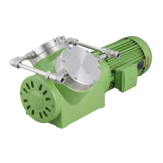
Diaphragm pump
Hide thumbs
Also See for N1200.12:
Table of Contents
Advertisement
Quick Links
Advertisement
Chapters
Table of Contents

Related Manuals for KNF N1200.12


Summary of Contents for KNF N1200.12
- Page 1 KNF 308930-308933 02/22 N1200.12, N1400.1.2.12 TRANSLATION OF ORIGINAL OPERATING AND INSTALLATION INSTRUCTION ENGLISH DIAPHRAGM PUMP Notice! Before operating the pump and accessories, read and observe the operating and installation instructions as well as the safety information!
-
Page 2: Table Of Contents
Index KNF Neuberger GmbH Alter Weg 3 1 About this document ............ 3 79112 Freiburg 1.1 Using the operating and installation instructions.. 3 Germany 1.2 Exclusion of liability........... 3 Tel. +49 (0)7664/5909-0 1.3 Symbols and markings.......... 4 Fax. +49 (0)7664/5909-99 2 Safety................ 6 2.1 Personnel and target group ........ 6... -
Page 3: About This Document
à In the event of uncertainties with regard to the content of the operating and installation instructions, please contact the manufacturer (contact data: see www.knf.com). Please have the type and serial number of the pump ready. à The individual chapters of these operating and installation instructions make reference to the operating instructions of the motor manufacturer for capacitor and three-phase motors. -
Page 4: Symbols And Markings
An activity to be carried out is specified here (a step). 1. The first step of an activity to be carried out is specified here. Follow other sequentially numbered steps. This symbol indicates important information. Translation of Original operating and installation instruction, English, KNF 308930-308933 02/22... - Page 5 Warning of electrical voltage Warning of poisonous substances Warning of hand injuries through crushing Observe the operating instructions General mandatory sign Wear hearing protection Environmentally conscious disposal Tab.2 Explanations of pictograms Translation of Original operating and installation instruction, English, KNF 308930-308933 02/22...
-
Page 6: Safety
Operating Only operate and install the pump under the operating parameters and op- parameters erating conditions described in Chapters 2.4 Operating conditions and 3 Technical data. Translation of Original operating and installation instruction, English, KNF 308930-308933 02/22... -
Page 7: Working In A Safety Conscious Manner
Before using a medium, check the compatibility of the media-contacting components (see 3 Technical data) with the medium. Only transfer gases that remain stable under the pressures and tempera- tures that arise in the pump. Translation of Original operating and installation instruction, English, KNF 308930-308933 02/22... -
Page 8: Use
The pumps must not be operated in explosive atmospheres. The pumps are not suitable for transferring the following: § Dusts § Liquids § Aerosols § Biological and microbiological substances Translation of Original operating and installation instruction, English, KNF 308930-308933 02/22... -
Page 9: Directives And Standards
EN 60034-30-1 (only pumps with three-phase motor) 2.8 Customer service and repair Customer service and repairs The pump is maintenance-free. However, KNF recommends periodic in- spection of the pump for obvious changes in noise or vibration. Only have repairs to the pumps performed by qualified KNF personnel. -
Page 10: Technical Data
Tab.7 *Acc. to ISO 228 Connection for water cooling Pump type Value N1200.12 Thread size G 1/4* N1400.1.2.12 Thread size G 1/4* Tab.8 *Acc. to ISO 228 Translation of Original operating and installation instruction, English, KNF 308930-308933 02/22... - Page 11 See operating instructions for motor voltage fluctuations Tab.10 *For further voltage and frequency variants, see type plate **See type plate Weight Pump type Weight [kg] N1200.12 approx. 60 N1400.1.2.12 approx. 82 Tab.11 Translation of Original operating and installation instruction, English, KNF 308930-308933 02/22...
- Page 12 For explanation on the task and principle, see Chapter 4 Product de- scription and function. à For information on installation and connection, see Chapter 6 Installa- tion and connection. à For information operation, see Chapter 7.1 General. Translation of Original operating and installation instruction, English, KNF 308930-308933 02/22...
-
Page 13: Product Description And Function
6 Motor fan cover 7 Electrical terminal box 8 Screw plug of the hole for pressure monitoring of the diaphragm innerspace (2x per head) 9 Pneumatic pump outlet Fig.2 Diaphragm pump N1400.1.2.12 Translation of Original operating and installation instruction, English, KNF 308930-308933 02/22... - Page 14 The closed innerspace (5) between the two diaphragms can be monitored for pressure change with the help of the hole(s) (6) provided for this purpose. Damage to the working diaphragm and safety diaphragm can thereby be de- tected immediately. Translation of Original operating and installation instruction, English, KNF 308930-308933 02/22...
-
Page 15: Transport
Storage temperature [°C] + 5 to + 40 Transport temperature [°C] - 10 to + 60 Permissible humidity (non-condens- 30 to 85 ing) [%] Tab.13 Transport parameter and storage parameter Translation of Original operating and installation instruction, English, KNF 308930-308933 02/22... -
Page 16: Transport With Carrying Strap
(3 Techni- cal data). NOTICE Transport with carrying strap Fig.4 Position of carrying strap (example) 1. Pull the carrying strap under the pump (see Fig. 4). Fig.5 Translation of Original operating and installation instruction, English, KNF 308930-308933 02/22... - Page 17 3. Make certain that the lifting load cannot be transferred from the belt to the pump connection. 4. Lift the pump from the packaging with the help of lifting gear. 5. Lower the pump carefully at the installation location. Translation of Original operating and installation instruction, English, KNF 308930-308933 02/22...
-
Page 18: Installation And Connection
Store the pump at the installation site to allow it to adapt to the ambient temperature before installation (condensation must not be allowed to form). à Mounting dimensions For mounting dimensions, see the following figures: Fig.6 Mounting dimensions pump series N1200.12 Translation of Original operating and installation instruction, English, KNF 308930-308933 02/22... - Page 19 Chapter 3 Technical data). à Make sure that access to moving parts is prevented. The IP protection class of the pump motor is specified on the type plate. Translation of Original operating and installation instruction, English, KNF 308930-308933 02/22...
-
Page 20: Electrical Connection
– the cables cannot be worn or damaged on sharp corners or edges – no tensile and pressure forces are exerted on the connection point of the cables (strain relief) Translation of Original operating and installation instruction, English, KNF 308930-308933 02/22... -
Page 21: Pneumatic Connection
In this way it is possible to prevent the transfer of possible pump vibrations and noises to the system. Translation of Original operating and installation instruction, English, KNF 308930-308933 02/22... -
Page 22: Installing Monitoring Device And Monitoring Diaphragm Innerspace
à Immediately stop the pump if the working di- aphragm breaks. Replace the working di- aphragm and safety diaphragm prior to further operation (see Chapter 8 Servicing). Translation of Original operating and installation instruction, English, KNF 308930-308933 02/22... -
Page 23: Connecting Water Cooling (Optional)
Mounting dimensions For mounting dimensions, see the following dimensional drawings: The base plate is shown as an additional accessory on the following dimensional drawings. Fig.9 Mounting dimensions pump series N1200.12 Translation of Original operating and installation instruction, English, KNF 308930-308933 02/22... - Page 24 Installation and connection Diaphragm Pump N1200.12, N1400.1.2.12 Fig.10 Mounting dimensions pump series N1400.1.2.12 Translation of Original operating and installation instruction, English, KNF 308930-308933 02/22...
-
Page 25: Operation
The pumps are built-in devices. Before they are commissioned, it must be ensured that the machines or systems into which the pumps are in- stalled comply with the relevant provisions. Translation of Original operating and installation instruction, English, KNF 308930-308933 02/22... - Page 26 When the pump is at a standstill, establish normal atmospheric pres- sure in the lines. Vapors as medium The service life of the diaphragm can be extended, if no condensate forms in the pump. Therefore: Translation of Original operating and installation instruction, English, KNF 308930-308933 02/22...
-
Page 27: Information On Switching The Pump On And Off
Recommissioning Before recommissioning, observe the applicable standards, guidelines, regulations and technical standards at the electrical connection. à Inspecting the pump Inspect the pump periodically for external damage or leakage. Translation of Original operating and installation instruction, English, KNF 308930-308933 02/22... -
Page 28: Servicing
(working diaphragm is broken). à Replace if the pressure or flow rate of the pump changes for no apparent reason. à At the latest, replace when the pump flow rate decreases. Tab.15 Translation of Original operating and installation instruction, English, KNF 308930-308933 02/22... -
Page 29: Cleaning
Allow the pump and the motor to cool. à Clean the pump and free the pump of hazardous materials. à Remove the hoses/pipes from the pneumatic pump inlet and outlet. Translation of Original operating and installation instruction, English, KNF 308930-308933 02/22... - Page 30 2 (per pump head) Reed valve 2 (per pump head) Valve limiter 2 (per pump head) Tab.16 * According to spare parts list, Chapter 10.1 Spare parts Fig. 11 ** According to Translation of Original operating and installation instruction, English, KNF 308930-308933 02/22...
- Page 31 26 Screw plug Removing the pump head 1. Accessing the fan blades: Loosen the fastening screws of the motor fan cowl (see Fig. 1 and Fig. 2) and remove the cowl. Translation of Original operating and installation instruction, English, KNF 308930-308933 02/22...
- Page 32 When remounting, use the exact same number of shim ring(s). 6. Loosen the three hexagon socket head cap screws (9); remove the in- termediate ring (22). Translation of Original operating and installation instruction, English, KNF 308930-308933 02/22...
- Page 33 Perform steps 1 to 21 for the second pump head. Changing reed valves 1. Loosen the two screws (2) and remove the valve limiters (3) and reed valves (5) from the intermediate plate (24). Translation of Original operating and installation instruction, English, KNF 308930-308933 02/22...
- Page 34 9. For two-headed pumps: Remount the pneumatic connection between the pump heads. In doing so, retighten the union nuts to the original position (as marked during disassembly, see Fig. 12). Translation of Original operating and installation instruction, English, KNF 308930-308933 02/22...
-
Page 35: Troubleshooting
Install the pump at the highest location in the sys- tem. à Working diaphragm, safety di- Replace the working diaphragm, safety di- aphragm or valves are worn or de- aphragm and valves (see Chapter 8 Servicing). fective. Tab.18 Translation of Original operating and installation instruction, English, KNF 308930-308933 02/22... - Page 36 Pump exhibiting changed running noises and vibrations. Cause Fault remedy à Pump bearing worn or defective. Determine the cause. à Contact KNF Customer Service. à Drive worn or defective. See operating instructions for drive. Tab.20 Translation of Original operating and installation instruction, English, KNF 308930-308933 02/22...
- Page 37 2. Clean the pump (see Chapter 8.2.2 Cleaning the pump). 3. Send the pump together with completed Health and Safety Clearance and Decontamination Form to KNF, stating the nature of the trans- ferred medium. Translation of Original operating and installation instruction, English, KNF 308930-308933 02/22...
-
Page 38: Spare Parts And Accessories
N1400.1.2SP.12E 315483 Tab.22 10.2 Accessories Accessories Order number Water cooling connection: N1200.12 305998 N1400.1.2.12 305445 Suction filter G1/4 316662 Base plate with rubber-bonded metal: 304440 N1200.12 304476 N1400.1.2.12 Tab.23 Translation of Original operating and installation instruction, English, KNF 308930-308933 02/22... -
Page 39: Returns
Returns KNF shall undertake to repair the pump only under the condition that the customer presents a certificate regarding the medium that is pumped and the cleaning of the pump. Please follow the instructions at knf.com/repairs here. -
Page 40: Appendix
Appendix Diaphragm Pump N1200.12, N1400.1.2.12 12 Appendix For further information, see also § Betriebsanleitung Drehstrommotor.pdf § CE-Erklärung Drehstrommotor.pdf Translation of Original operating and installation instruction, English, KNF 308930-308933 02/22... - Page 41 Operating manual for three-phase motors (IE2 + IE3 in accordance with IEC 60034-30-1) Frame size HEFIE2 / IE3 56L/.. - HEFIE2 / IE3 450L/.. Issue:2.0 - 07/21 © All rights reserved...
- Page 42 EMOD Motoren GmbH Electric motor factory Zur Kuppe 1 36364 Bad Salzschlirf Germany Phone: +49 6648 51-0 Fax: +49 6648 51-143 info@emod-motoren.de www.emod-motoren.de...
- Page 43 Table of contents General information Area of application Explanation of the labels used List of safety and installation notes Limitation of liability Safety Transportation and storage Transportation Storage Installation and commissioning Positioning 3.1.1 Location Mountings for motors Condensation drain holes Balancing Insulation resistance check Electrical connection...
-
Page 44: General Information
General information Note The safety instructions contained in this operating manual must be observed! Special designs and structural variants may differ from the basic type in terms of technical details. If there are any uncertainties, we strongly advise you to contact EMOD Motoren GmbH. -
Page 45: List Of Safety And Installation Notes
List of safety and installation notes Caution Electric motors have dangerous, live and rotating parts. All work during connection, commissioning, maintenance and disposal may only be carried out by qualified professionals. (Observe EN50110-1 and IEC 60364) Before beginning any work, any in particular before opening covers, the drive must be isolated according to regulations. -
Page 46: Safety
The obligations agreed in the supply contract, the general terms and conditions, as well as the manufacturer’s delivery conditions, and the applicable statutory provisions at the time of signing of the contract apply. We reserve the right to make technical changes within the context of the performance characteristics and further development. -
Page 47: Installation And Commissioning
Installation and commissioning Danger Installations and work may only be carried out with the device deenergised (separated from the mains) and the motor shut down. Death, cardiac arrhythmia ► Observe the 5 safety rules, see chapter List of safety and installation notes on page 5 Positioning 3.1.1 Location... -
Page 48: Electrical Connection
insulation resistance at a winding temperature of 25 °C is smaller than 30 MΩ, or smaller than 1 MΩ at a winding temperature of 75 °C, the motor winding should be dried until the required minimum insulation resistance is reached. The winding temperature should not exceed 80 °C in this regard! Loosen the bearing plate, so that an air exchange can be carried out with closed motors. -
Page 49: Maintenance
• Additional devices which are present (e.g. brakes) are functional, • The coolant supply is not restricted, • Measures have been taken to protect against contact with moving and live parts. Maintenance Danger Installations and work may only be carried out with the device deenergised (separated from the mains) and the motor shut down. -
Page 50: Repair
Caution When re-lubricating the bearings, the grease drain screws on the DE side and NDE side bearing plate, where present, must always be opened! Cleaning intervals The regular removal of old grease is necessary in order not to negatively affect the expected service life of the bearings. -
Page 51: Appendix
Appendix Table 1: Lubricants Operating conditions Insulation class Roller bearing grease / area of application High-temperature and long-term lubricant Normal -40 °C to +180 °C High temperatures, High-temperature and long-term lubricant extreme operating conditions -20 °C to +180 °C Low-temperature lubricant Low temperatures -50 °C to +150 °C Table 2: Tightening torques for terminal board connection screw connections... - Page 52 Table 3: Spare parts Part no. Description Housing (IMB3) Housing without feet (IMB5 / IMB14) Motor feet Stator package with winding Rotor with shaft 4.0. Bearing plate AS (IMB3) Flange bearing plate (IMB5) Flange bearing plate (IMB14) Bearing plate BS Bearing cover ASi Bearing cover ASa Bearing cover BSi...
-
Page 54: Declaration Of Conformity
Declaration of conformity EC Declaration of conformity Document no./month/year 1.51.821.010/07.21 Manufacturer EMOD Motoren GmbH Address Zur Kuppe 1 D-36364 Bad Salzschlirf Product description Three-phase motors Type (frame size) HEF IE2 56L/.. - HEF IE2 450L/.. HEF IE3 56L/.. - HEF IE3 450L/.. Three-phase motors in accordance with Directive 2009/125/EG, Regulation (EU) No. -
Page 55: Documents Provided
Documents provided • Circuit diagram... - Page 56 Emod Motoren GmbH Elektromotorenfabrik Anschlussschaltbild(er) Connection diagram(s) Hausanschrift/ address: Zur Kuppe 1 D- 36364 Bad Salzschlirf Tel. 06648 51-0 Fax. 06648 51-143 info@emod-motoren.de www.emod-motoren.de...
- Page 60 KNF worldwide You can find our local KNF partners at: www.knf.com...
Need help?
Do you have a question about the N1200.12 and is the answer not in the manual?
Questions and answers