Table of Contents
Advertisement
Quick Links
Advertisement
Table of Contents

Related Manuals for KNF N 813


Summary of Contents for KNF N 813
- Page 1 KNF 347376-347567 09/23 N813_DC-B (MBL) TRANSLATION OF ORIGINAL OPERATING AND INSTALLATION INSTRUCTION ENGLISH DIAPHRAGM PUMP Notice! Before operating the pump and accessories, read and observe the operat- ing and installation instructions as well as the safety information!
-
Page 2: Table Of Contents
Contents 1 About this document ................ 3 1.1 Using the operating and installation instructions...... 3 1.2 Exclusion of liability............... 3 1.3 Symbols and markings.............. 4 2 Safety .................... 6 2.1 Personnel and target group ............ 6 2.2 Responsibility of the operator ............ 7 2.3 Working in a safety conscious manner ......... -
Page 3: About This Document
The manufacturer assumes no liability for damages and mal- functions resulting from impermissible spare parts and acces- sories. Translation of Original Operating and Installation Instruction, KNF 347376-347567 09/23... -
Page 4: Symbols And Markings
An activity to be carried out is specified here (a step). 1. The first step of an activity to be carried out is specified here. Other sequentially numbered steps follow. This symbol indicates important information. Translation of Original Operating and Installation Instruction, KNF 347376-347567 09/23... - Page 5 General warning symbol Warning of hot surface Warning of electrical voltage Warning of poisonous substances Warning of hand injuries through crushing Observe the operating instructions General mandatory sign Tab.2: Explanation of pictograms Translation of Original Operating and Installation Instruction, KNF 347376-347567 09/23...
-
Page 6: Safety
Tab.3: Target group Who-does-what Lifecycle phase User Specialized per- matrix sonnel Transport Mounting Connection Commissioning Operation Servicing Troubleshooting Disposal Tab.4: Who-does-what matrix Translation of Original Operating and Installation Instruction, KNF 347376-347567 09/23... -
Page 7: Responsibility Of The Operator
Make sure that an EMC-compliant installation of the pump is ensured at all times to prevent the occurrence of dangerous situations. Translation of Original Operating and Installation Instruction, KNF 347376-347567 09/23... -
Page 8: Operating Conditions
Make sure that a dangerous situation cannot arise as a result. When pumping hazardous media, observe the safety regula- tions for the handling of said media. Translation of Original Operating and Installation Instruction, KNF 347376-347567 09/23... -
Page 9: Use
2.6.2 Foreseeable misuse The pumps must not be operated in explosive atmospheres. The pumps are not suitable for transferring the following: § Dusts § Liquids § Aerosols § Biological and microbiological substances Translation of Original Operating and Installation Instruction, KNF 347376-347567 09/23... -
Page 10: Directives And Standards
§ Directive 2011/65/EU on the restriction of the use of cer- tain hazardous substances in electrical and electronic equipment (Annex II changed by delegated Directive (EU) 2015/863 of the Commission) Translation of Original Operating and Installation Instruction, KNF 347376-347567 09/23... -
Page 11: Customer Service And Repair
Alternatively, KNF products (old devices) may also be returned to KNF for a fee (see chapter 11 Re- turns [} 55]). Translation of Original Operating and Installation Instruction, KNF 347376-347567... -
Page 12: Technical Data
**Liters in the standard state (based on ISO 8778 and ISO 21360-1/2) (1013 hPa, 20°C) Pneumatic connections Parameter Value Inlet Thread size G1/8 Outlet Thread size G1/8 Tab.7: Pneumatic connections Translation of Original Operating and Installation Instruction, KNF 347376-347567 09/23... - Page 13 Max. permissible supply volt- ± 10% age fluctuations Motor protection class (DIN IP20 EN 60529 / IEC 60529) Overcurrent limit of motor electronics [A] Tab.8: Electrical performance *Further voltage variants on request Translation of Original Operating and Installation Instruction, KNF 347376-347567 09/23...
- Page 14 Highest permissible relative 80% for temperatures up to air humidity of the environ- 31°C, decreasing linearly to ment 50% at 40°C. Maximum installation altitude 2000 [m above sea level] Tab.10: Other parameters Translation of Original Operating and Installation Instruction, KNF 347376-347567 09/23...
-
Page 15: Product Description
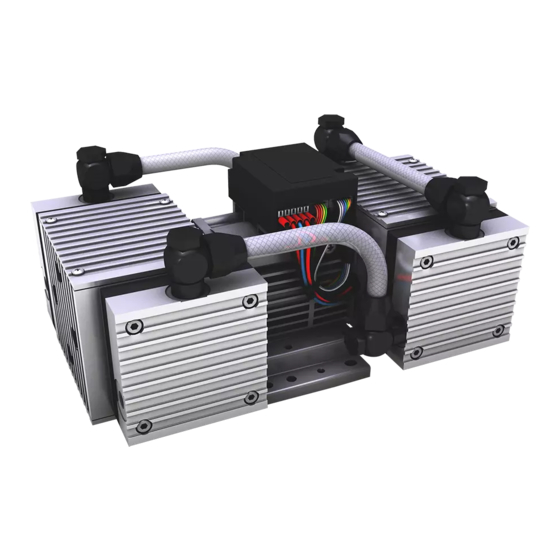
Product description Diaphragm pump N813_DC-B (MBL) 4 Product description Design 1 Pneumatic pump inlet 2 Pneumatic pump outlet 3 Pneumatic head connec- tion 4 Motor Fig.1: Design N813.3_DC-B Translation of Original Operating and Installation Instruction, KNF 347376-347567 09/23... - Page 16 Product description Diaphragm pump N813_DC-B (MBL) 1 Pneumatic pump inlet 2 Pneumatic pump outlet 3 Pneumatic head connec- tion 4 Motor Fig.2: Design N813.4_DC-B Translation of Original Operating and Installation Instruction, KNF 347376-347567 09/23...
- Page 17 (2). In the upwards stroke, the diaphragm presses the medium out of the pump head via the outlet valve (1). The transfer chamber (3) is separated from the pump drive by the di- aphragm. Translation of Original Operating and Installation Instruction, KNF 347376-347567 09/23...
-
Page 18: Transport
There is a risk of injury from cutting on the sharp edges when grabbing cor- CAUTION ners or when opening the packaging. à Where appropriate, wear suitable personal protective equipment (e.g., safety shoes, safety gloves). Translation of Original Operating and Installation Instruction, KNF 347376-347567 09/23... - Page 19 Permissible humidity (non- 30 to 85 condensing) [%] Tab.11: Transport parameters and storage parameters Prior to commissioning, make sure that the pump has reached the ambient temperature (3 Technical data [} 12]). NOTICE Translation of Original Operating and Installation Instruction, KNF 347376-347567 09/23...
-
Page 20: Installation And Connection
Store the pump at the installation site to allow it to adapt to the ambient temperature before installation (condensa- tion must not be allowed to form). à Mounting dimen- For mounting dimensions, see the following illustrations: sions Translation of Original Operating and Installation Instruction, KNF 347376-347567 09/23... - Page 21 Installation and connection Diaphragm pump N813_DC-B (MBL) Fig.4: Mounting dimensions N813.3_DC-B Translation of Original Operating and Installation Instruction, KNF 347376-347567 09/23...
- Page 22 (head, motor). à Installation loca- Make sure that the installation location is dry and that the tion pump is protected from rain, spray water, splash water, dripping water and other contaminants. Translation of Original Operating and Installation Instruction, KNF 347376-347567 09/23...
-
Page 23: Electrical Connection
Install a device for separating the pump motor from the electrical grid in the electrical installation (e.g. in accor- dance with EN 60335-1). Refer to the type plate for the maximum current con- sumption of the pump. Translation of Original Operating and Installation Instruction, KNF 347376-347567 09/23... - Page 24 NOTICE electronics. Control voltage may only be applied if the drive controller is supplied with an operating voltage. The drive controller may otherwise be damaged. NOTICE Translation of Original Operating and Installation Instruction, KNF 347376-347567 09/23...
- Page 25 Leads connections Function Wire lead Signal name Size color + Supply voltage AWG 18 - Supply voltage (0 V) Black / GND AWG 18 Tab.12: Connection diagram for drive controller Translation of Original Operating and Installation Instruction, KNF 347376-347567 09/23...
- Page 26 Installation and connection Diaphragm pump N813_DC-B (MBL) Fig.7: Connection diagram for drive controller Translation of Original Operating and Installation Instruction, KNF 347376-347567 09/23...
- Page 27 Control voltage description: Min. Max. min. → Min. pump flow rate max. → Max. pump flow rate PWM signal PWM frequency range [Hz] [50 … 150] Duty cycle range 0 … 100 Translation of Original Operating and Installation Instruction, KNF 347376-347567 09/23...
-
Page 28: Pneumatic Connection
In this way it is possible to prevent the transfer of possible pump vibrations and noises to the sys- tem. Translation of Original Operating and Installation Instruction, KNF 347376-347567 09/23... - Page 29 4. Lay the suction line and pressure line with a descent so that no condensate can run into the pump. Pneumatic noises can be reduced or dissipated by using a silencer. Translation of Original Operating and Installation Instruction, KNF 347376-347567 09/23...
-
Page 30: Operation
The pumps are built-in devices. Before they are commis- sioned, it must be ensured that the machines or systems into which the pumps are installed comply with the rele- vant provisions. Translation of Original Operating and Installation Instruction, KNF 347376-347567 09/23... - Page 31 NOTICE of the pump. Further information is available from KNF Customer Service (contact data: see www.knf.com). Translation of Original Operating and Installation Instruction, KNF 347376-347567 09/23...
- Page 32 à KNF recommends: When pumping corrosive media, flush the pump before switching off (see Chapter 8.2.1 Flushing the pump [} 41]) to extend the service life of the di- aphragm. Translation of Original Operating and Installation Instruction, KNF 347376-347567 09/23...
-
Page 33: Information On Switching The Pump On And Off
Speed range The speed range from n to n is derived by scaling to the control voltage U Ctrl à : 0.1 V Ctrl min à : 5.0 V Ctrl max Translation of Original Operating and Installation Instruction, KNF 347376-347567 09/23... - Page 34 à Changing the control voltage values U and U Ctrl min Ctrl max à If the control voltage is lower than U , the motor is ON. Ctrl min Translation of Original Operating and Installation Instruction, KNF 347376-347567 09/23...
- Page 35 The drive controller generates a speed-synchronous pulse width modulation signal. Fig.10: Analog speed output (standard) Optional speed output The drive controller generates a speed-synchronous square wave frequency with 5V TTL level. Translation of Original Operating and Installation Instruction, KNF 347376-347567 09/23...
- Page 36 Pin 1 – Do not connect Pin 2 – Do not connect Pin 3 – GND Pin 4 – 5V (max. 50 mA) Pin 5 – TX MBLC Pin 6 – RX MBLC Translation of Original Operating and Installation Instruction, KNF 347376-347567 09/23...
- Page 37 RS232 interface. It is managed accordingly in the operating system as an additional COM connection and can be addressed with conventional terminal software. Interface configuration à Baud rate: 57600 bits/s à Data bits: 8 à Parity: none Translation of Original Operating and Installation Instruction, KNF 347376-347567 09/23...
- Page 38 Target motor speed gS ns ; E Minimum possible nl ; E Motor speed Maximum possible nh ; E Motor speed Software version V ; E number Tab.15: Read commands Translation of Original Operating and Installation Instruction, KNF 347376-347567 09/23...
- Page 39 7.3.5 Exter- nal digital actuation [.29 version] [} 36]. Parameter Value Rx KNF MBLC Low: 0V…0.9V High: 4.2V…5.2V Tx KNF MBLC Low: 0V…0.6V High: 4.5V…5.2V Translation of Original Operating and Installation Instruction, KNF 347376-347567 09/23...
-
Page 40: Servicing
Servicing may only be performed according to the legal regulations (e.g. work safety, environmental protection) and provisions. à Servicing may only be performed by specialized personnel or trained and instructed personnel. Translation of Original Operating and Installation Instruction, KNF 347376-347567 09/23... -
Page 41: Servicing Schedule
8.2.1 Flushing the pump When transferring dangerous and environmentally hazardous media, KNF recommends flushing the pump with air at atmo- spheric pressure for a few minutes prior to switch-off (if nec- essary for safety reasons: with an inert gas) to extend the ser- vice life of the diaphragm. -
Page 42: Replacing Diaphragm And Valves
(ensure resistance of the material). à If compressed air is available, blow out the components. 8.3 Replacing diaphragm and valves à Requirements Disconnect the drive from the mains and ensure that it is deenergized. Translation of Original Operating and Installation Instruction, KNF 347376-347567 09/23... - Page 43 Always replace the diaphragm and valves together so as to maintain the performance and safety of the pump. Spare parts Parts Item number* Quantity per head Valves Sealing ring Diaphragm Tab.18: Spare parts Translation of Original Operating and Installation Instruction, KNF 347376-347567 09/23...
- Page 44 3 Head plate 4 Hexagon socket screw 5 Cover 6 Valve 7 Sealing ring 8 Diaphragm 9 Shim(s) 10 Connecting 11 Counter- weight Fig.13: Pump head (exploded view, symbolic) Translation of Original Operating and Installation Instruction, KNF 347376-347567 09/23...
- Page 45 Servicing Diaphragm pump N813_DC-B (MBL) 12 Pneumatic connection 14 Pneumatic connection Fig.14: Pneumatic connections (diagrammatic figure) Translation of Original Operating and Installation Instruction, KNF 347376-347567 09/23...
- Page 46 Removing the pump head (for each head separately) 1. Mark the head plate (3), intermediate plate (2) and hous- ing (1) with a continuous felt-tip pen line (M). This helps to avoid incorrect assembly later. Translation of Original Operating and Installation Instruction, KNF 347376-347567 09/23...
- Page 47 6. Insert the sealing rings into the intermediate plate. f) Mounting the pump head 1. Move the diaphragm (8) to top dead center via the coun- terweight (11). Translation of Original Operating and Installation Instruction, KNF 347376-347567 09/23...
- Page 48 Fitting the connection 1. Reassemble the pneumatic head connection(s). If you have questions with regard to maintenance, please con- tact your KNF technical adviser (telephone number: see last page). Translation of Original Operating and Installation Instruction, KNF 347376-347567 09/23...
-
Page 49: Spare Parts And Accessories
Spare parts and accessories Diaphragm pump N813_DC-B (MBL) 9 Spare parts and accessories To order spare parts and accessories, please contact your KNF sales partner or KNF Customer Service (con- tact data: see www.knf.com). 9.1 Spare parts Spare part set... -
Page 50: Troubleshooting
à Check and ensure that no voltage is present. à Allow the pump to cool before troubleshooting. à Check the pump (see following tables). Translation of Original Operating and Installation Instruction, KNF 347376-347567 09/23... - Page 51 Ensure correct polarity of the connection leads and connect the pump. à Diaphragm and valves Replace diaphragm and valves (see Chapter 8 Ser- are worn or defective. vicing [} 40]). Tab.23: Translation of Original Operating and Installation Instruction, KNF 347376-347567 09/23...
- Page 52 Replace diaphragm and valves (see Chapter 8 Ser- are worn or defective. vicing [} 40]). à Replaced diaphragms Ensure that shim rings were fitted on the diaphragm and valve plates. thread. Translation of Original Operating and Installation Instruction, KNF 347376-347567 09/23...
- Page 53 If desired, the drive controller can be programmed so that the voltage of the fault output has the same characteristic as the LED. The manufacturer only provides for logic 1 or 0 via a voltage at the fault output. Translation of Original Operating and Installation Instruction, KNF 347376-347567 09/23...
- Page 54 Fault cannot be rectified If you are unable to identify any of the specified causes, send the pump to KNF Customer Service (contact data: see www.knf.com). 1. Flush the pump with air for a few minutes (if necessary for...
-
Page 55: Returns
If necessary, request original packaging for a fee. Returns KNF shall undertake to repair the pump only under the condi- tion that the customer presents a certificate regarding the medium that is pumped and the cleaning of the pump. In this case too, old devices can be returned. - Page 56 KNF Neuberger GmbH Alter Weg 3 79112 Freiburg Germany Tel. +49 (0)7664/5909-0 E-mail: info.de@knf.com www.knf.com KNF worldwide You can find our local KNF partners at: www.knf.com...
Need help?
Do you have a question about the N 813 and is the answer not in the manual?
Questions and answers