Table of Contents
Advertisement
Quick Links
Advertisement
Table of Contents

Related Manuals for AMGO PRO-18A


Summary of Contents for AMGO PRO-18A
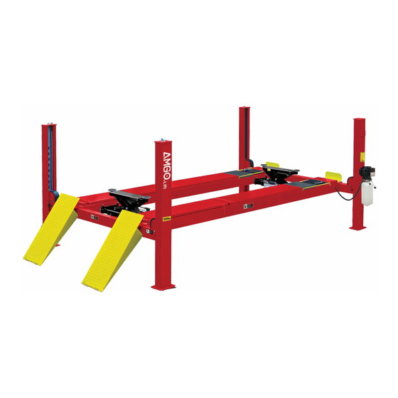
- Page 1 FOUR POST LIFT Model: PRO-18A...
-
Page 2: Table Of Contents
CONTENTS Product Features and Specifications ............. 1 Installation Requirement ……………………………………………………………………………… 2 Steps of Installation …................ 3 Exploded View ..................23 Test Run ……….................. 26 Operation Instruction ............... 27 Maintenance ................... 28 Trouble Shooting ................29 Parts List ..................30... -
Page 3: Product Features And Specifications
I. PRODUCT FEATURES AND SPECIFICATIONS ALIGNMENT MODEL PRO-18A FEATURES · Manual control air-operated system. · Mechanical self-lock and air-drive safety release. · Manual hydraulic power system, cable-drive. · Strengthen and Non-skid diamond platforms. · Multiple turn plate pockets fit with different wheel base. -
Page 4: Installation Requirement
II. INSTALLATION REQUIREMEN A. TOOLS REQUIRED Rotary Hammer Drill (Φ19) Carpenter’s Chalk Hammer Screw Sets Level Bar Tape Measure (7.5m) English Spanner (12") Pliers Wrench Set Lock Wrench , 12 , 13 , 14 , 17... -
Page 5: Steps Of Installation
B. SPECIFICATIONS OF CONCRETE (See Fig. 3) Specifications of concrete must be adhered to the specification as following. Failure to do so may result in lift and/or vehicle falling. 1. Concrete must be thickness 100 mm minimum and without reinforcing steel bars, and must be dried completely before the installation. - Page 6 2. Open the outer packing carefully (See Fig. 5) Parts box Drive-in Ramp Cross Beam Column Offside Platform Power side Platform Shipment Parts List Fig. 5 3. Take off the Drive-in Ramps and Columns (See Fig. 6) Fig. 6 4. Loose the screws of the upper package stand, take off the offside platform, take out the parts inside the power side platform, than remove the package stand.
- Page 7 6. Open the carton of parts and check the parts according to the parts box list (See Fig. 8) Fig. 8 7. Check the parts of the parts bag according to the parts bag list (See Fig. 9) Parts bag 1 Parts bag 2 Fig.
- Page 8 Make sure the size is right and base is flat (see Fig. 10). Note: Reserve space before and behind the installation site. 、 Car in Use a carpenter’s chalk line to establish Direction installation layout Fig. 10 Model PRO-18A 229-1/2” 137” 267-1/4” - 6 -...
- Page 9 D. Install cross beams (See Fig. 11, Fig. 12) Hole towards inside Fig. 11 Fig. 12 - 7 -...
- Page 10 E. Fix the anchor bolts 1. Prepare the anchor bolts (See Fig. 13). Spring washer Washer Fig. 13 2. Using the prescribed rotary hammer drill, and drill all the anchor holes and install the anchor bolts, do not tighten the anchor bolts first (See Fig.
- Page 11 2. Install safety ladders (See Fig. 16). This height should be the same for four safety ladders Safety ladder pass through the hole of the top plate, then tighten the two nuts Fig. 16 G. Put the Cross Beams at the same height (See Fig.
- Page 12 H. Install power side platform. 1. Put the power side platform upon the cross beams by fork lift or manual, offset the cross beams to the outside till the pulleys of both platforms can set up into the cross beam , Install the power side platform and screw up the bolts (See Fig.18) (See Fig.19)
- Page 13 I. Assembly offside platform and slider block, check the vertical of columns with Level bar, adjusting with the shims if not, and then tighten the anchor bolts (See Fig. 20). 3-15 3-16 Note: Torque of Anchors is 150N.m. Using the ratchet spanner with socket to tighten the bolts 3-14 Install the slider block...
- Page 14 J. Install cables 1. Pass through the cables from the platform to the columns according to the number of the cables (See Fig. 21). Fig. 21 ○ ○ ○ ○ Cable Length 177-1/8” 471-5/8” 249-3/4” 398-1/4” (inc. connecting fitting) Fig. 21 - 12 -...
- Page 15 2. The cable pass through the cross beam to top plate of columns and be screwed with cable nuts (See Fig. 22). Cable pass through top plate and be screwed Cable pass through with cable nuts. between the big pulley and tension pulley Cable Pulle...
- Page 16 3. Illustration for platform cables (See Fig. 23). Limit Slider cable ④ cable ② cable ② cable ④ cable ① cable ③ cable ④ cable ④ cable ③ cable ② cable ② cable ① cable ② cable ④ M10*150 Hex Bolt Fig.
- Page 17 J. Install oil-water separator, manual control air valve and power unit (See Fig. 24). Air inlet Air outlet Fig. 24 Air direction of oil-water separator The side marking “P” on the air valve is Air Input. direction Fig. 24 - 15 -...
- Page 18 L. Install hydraulic system (See Fig. 25). Note: Oil hoses and oil return pipe connected to oil cylinder must be passed above the cable and cylinder inlet port must swing upward to avoid the oil hose and oil return pipe scratched by cable. Cylinder inlet port swings upward Retainer Protective Ring...
- Page 19 6*4 3. Connecting air solenoid valve using black air line (See Fig. 27) Air cylinder fitting Air cylinder fitting Rear Cross Beam Front Cross Beam retainer Power side platform Cut air line between two clips ,and connect to T- fitting retainer Fig.26 Air cylinder fitting...
- Page 20 4. Connecting Oil hose and Air lines (See Fig. 28) Oil hose of optional Optional air line Jack pass through this through this hole hole Connecting Black air line ¢6×¢4 to Manual control air valve Oil returned hose pass through this hole Fig.
- Page 21 6. Connecting air inlet (Air supply pressure 5 kg/cm - 8 kg/cm ), adjusting the air pressure of Oil-water separator to 0.4 - 0.6MPa. (See Fig. 30) Connecting air inlet Clockwise to increase the air pressure Counter-clockwise to reduce the air pressure Adjusting the air pressure to 0.4~0.6MPa Fig.
- Page 22 N. Install Electrical System Connect the power source on the data plate of Motor. Note: 1. For the safety of operators, the power wiring must contact the floor well. 2. Pay attention to the direction of rotations when using 380V, three phase motors.
- Page 23 P. Install spring and safety cover of cross beam (See Fig. 32) Fig. 32 - 21 -...
- Page 24 Q. Install Drive-in ramp, Tire stop plate, Platform lock plates, Steel ball set (See Fig. 33) Install Tire stop plate Install Drive-in ramp Fig. 33 - 22 -...
-
Page 25: Exploded View
IV. EXPLODED VIEW Model PRO-18A When using turn plates, need to put a #1 adjustable block for turn plate with 35mm on each side. Fig. 34 - 23 -... - Page 26 CROSS BEAM Fig. 35 CYLINDERS Fig. 36 - 24 -...
- Page 27 MANUAL POWER UNIT Manual 220V 60Hz 1PH Fig. 37 - 25 -...
-
Page 28: Test Run
Illustration of Hydraulic Valve for power unit 220V,60Hz,Single phase manual power unit See Fig.38 Protective ring Oil return port Relief valve Release valve Throttle valve Oil Outlet Handle of Release valve Check valve Fig.38 V. TEST RUN 1. Fill the reservoir with approximately 14L Hydraulic Oil (Note: In consideration of Power Unit’s durability,please use Hydraulic Oil 46#). -
Page 29: Operation Instruction
Circuit Diagram of Hydraulic System 1. Filter 2. Gear pump 3. Cushion valve 4. Relief valve 5. Motor 6. Throttle valve 7. Release valve 8. Check valve 9. Cylinder for four post lift Fig. 39 VI. OPERATION INSTRUCTIONS To lift vehicle 1. -
Page 30: Maintenance
VII. MAINTENANCE SCHEDULE Monthly: 1. Re-torque the anchor bolts to 150 Nm; 2. Lubricate cable with lubricant; 3. Check all cable connection, bolts and pins to insure proper mounting; 4. Make a visual inspection of all hydraulic hoses/lines for possible wear or leakage; 5. -
Page 31: Trouble Shooting
VIII. TROUBLE SHOOTING TROUBLE CAUSE REMEDY 1. Button does not work 1.Replace button 2.Wiring connections are not in good 2.Repair all wiring connections condition Motor does 3. Motor burned out 3.Repair or replace motor not run 4. AC contactor burned out 4.Replace AC contactor 5. -
Page 32: Parts List
IX. PARTS LIST FOR PRO-18A Item Part# Description QTY. Note 460021 Power side Column 460020 Offside Column 476017 Cross Beam Assy. 476016 Slider block 209059 Anchor Bolt 16 set 410022 Safety Ladder 476014 Hex Nut 477001 Power side Platform 476010 Pulley Shaft Assy. - Page 33 Item Part# Description QTY. Note 420031 Tire stop plate 201005 Split pin 620065/ Shim 20 each 201090 209056 Self locking Nut 420217 Cable limit pin Plate for Adjustable Turn plate 477005 430006 Pin For Slip Plate 477003 Slip Plate 420157 Steel Ball Set Platform Lock Plate 420137...
- Page 34 - 32 -...
- Page 35 Parts For Cross Beam 460064 Cross Beam 460043 Cross beam Safety Cover 209009 Cup Head Bolt 420044 Limit Plate 420138 Socket Bolt 420038 420037 Snap Ring 420033 Spring 209021 Hex Nut 3-10 420049 Split Pin 3-11 420048 Air Cylinder 3-12 420047 Fitting for Air Cylinder 3-13...
- Page 36 81400290 Filter net 81400143 Steel cover motor 10420070 Push button 41030055 AC connector 81400287 Cover of Motor Terminal Box 71111105 AMGO Name plate 81400296 81400459 Throttle valve body 10209069 O ring 81400266 Relief valve 81400284 Iron plug 10720118 Shaft pin...
- Page 37 - 35 -...
Need help?
Do you have a question about the PRO-18A and is the answer not in the manual?
Questions and answers