Table of Contents
Advertisement
Quick Links
Advertisement
Table of Contents

Related Manuals for SportsArt Fitness N961


Summary of Contents for SportsArt Fitness N961
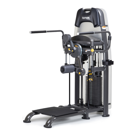
- Page 1 S961 Total Hip Owner’s Manual...
-
Page 2: Table Of Contents
S961 OWNER’S MANUAL CONTENTS 1. INTRODUCTION ................2 2. SAFETY PRECAUTIONS ..............3. LIST OF PARTS ................. 4. ASSEMBLE THE PRODUCT ............. STEP 1 Install the Rear Covers.............. STEP 2 Install the Main Frame .............. STEP 3 Install the Handles ..............STEP 4 Install the Leg Cushion ............. -
Page 3: Introduction
1. INTRODUCTION Congratulations on the purchase of a high quality SportsArt product, the S961 Total Hip machine. Constructed of high quality materials and designed for years of reliable performance, this product was made for full commercial use. Before this product is assembled or operated, we recommend that you familiarize yourself with this manual. -
Page 4: Safety Precautions
2. SAFETY PRECAUTIONS This product was designed and built for optimum safety. However certain precautions apply during the use of this product. Please note the following safety precautions: • Please read the entire manual before assembly and operation. Make sure the product is installed and operated as instructed in this manual. •... -
Page 5: List Of Parts
3. LIST OF PARTS Assembly Parts Name Qty. No. Name Qty. Weight Stack Frame A4 Left Handle A1a Rear Cover, Top A5 Right Handle A1b Rear Cover, Bottom A6 118 Oval Foot Cover A Support Frame A7 118 Oval Foot Cover B Leg Cushion A8 Storage Tray... - Page 6 Components in the Hardware Kit Name Qty. Specification Notes Cover cap D23*t8.8 Push revits L-shaped Allen wrench L-shaped Allen wrench Double open-end wrench 8*17 Double open-end wrench 8*10 Double open-end wrench 13.2*15.2 Double open-end wrench 17*23 Components on the Product Name Specification Notes...
-
Page 7: Assemble The Product
4. ASSEMBLE THE PRODUCT Follow instructions below to assemble this product. Note that in this manual the words “left” and “right” are used to refer to the product and its parts. As such, these designations correspond to the “left” and “right” sides of a person in position to exercise on this product. -
Page 8: Step 2 Install The Main Frame
STEP 2 Install the Main Frame When assembling the main frames, please have at least three people to assemble due to safety reasons. (a). Please remove screws (20) from the weight stack frame (A1) and the support frame (A2). (b). With one person holding the weight stack frame up, connect the support frame (A2) to the weight stack frame (A1), and use screws (20) to secure the assembly. -
Page 9: Step 3 Install The Handles
STEP 3 Install the Handles (a). Remove screws (21) from the weight stack frame (A1). (b). Attach the both left and right handles (A4)(A5) onto the weight stack frame (A1), then use screws (21) to secure the assembly. -
Page 10: Step 4 Install The Leg Cushion
STEP 4 Install the Leg Cushion (a). Remove the screws (22) from the leg cushion (A3). (b). Shown below, connect the rotational connector of the leg cushion (A3 to the weight stack frame (A1). Use screws (22) to secure the assembly and then cover it with cork cover (10). -
Page 11: Step 5 Install The Foot Covers
STEP 5 Install the Foot Covers (a). Attach the oval foot covers (A6)(A7) onto the weight stack frame (A1) and the support frame (A2). Align the ends before using the push rivets (10) to secure the foot covers together. Note: While installing the weight stack covers, if it can not be put together due to the Interference of the machine, please swap the direction of the covers. -
Page 12: Step 6 Install The Storage Tray Holder
STEP 6 Install the Storage Tray Holder Please follow the instructions (a) through (b) to install the storage tray (a). Locate the position where the storage tray (A8) attaches to the weight stack frame (A1), then remove the screws (23) from the weight stack frame. (b). -
Page 13: Step 7 Minor Weight Stack Instructions
STEP 7 Minor Weight Stack Instructions To adjust the minor weight stack, insert the upper pin to add 3.5Lbs/1.5kgs or the lower pin to add 6.5Lbs/3kgs. When the minor weights are not in use, pull the pin to release the weight. -
Page 14: Step 8 Belt Tension Adjustment Instructions
STEP 8 Belt Tension Adjustment Instructions 1. After the installation and the final positioning of the machine, make the appropriate adjustments to ensure that the machine is working. 2. If the belt is too tight or too loose, first loosen nut A as shown then adjust nut B. -
Page 15: Operate The Product
5. OPERATE THE PRODUCT OPERATION Operate the Product (a). The rotator adjusting pin is used for adjusting the rotator to the proper initial position for the user. Shown in area (A). (b). The rotator adjusting pin is used for user to adjust the plate to the proper position. -
Page 16: Maintenance
6. MAINTENANCE This section covers maintenance topics and includes a maintenance schedule, task list, and log. MAINTENANCE Machine Maintenance 1. Please clean and lubricate the guide rod once a week. (a). Use a clean, lint-free towel to apply the lubricant onto the guide rods. (b). - Page 17 MAINTENANCE Machine Maintenance IMPORTANT NOTE 1. Once the machine belt reaches the warranty period, it is recommended to replace the belt. 2. Belt safety check, after a year in use, check belt weekly. Depend on the use conditions, increase the frequency of inspections. (As shown: (A) a belt, (B) the belt extension) During inspection, if found cracks in the belt or the belt is exposed to other unusual circumstances, please immediately stop using the machine and...
-
Page 18: Maintenance Schedule
MAINTENANCE Schedule Area Week Month Quarter Year Notes Exterior Clean. Screws Inspect for looseness and secure if necessary. Testing To confirm that the machine is working properly Glide Rail Wipe dirt off with a cloth. Belt Check for damage or wear. -
Page 19: Maintenance Task List
MAINTENANCE Task List Like cars, fitness products require maintenance. Regular maintenance ex- tends product life, and failure to maintain products can void the manufac- turer’s warranty. Copy the maintenance log sheet, and record maintenance work for each fitness product. Daily tasks 1. -
Page 20: Maintenance One-Year Maintenance Log
MAINTENANCE One-Year Maintenance Log Facility:_______________________ Supervisor:____________________ Product model number:__________ Serial number:_________________ Start date: ____________________ End date:_____________________ Daily Tasks Weeks 1-7 Weeks 8-14 Weeks 15-21 Week 22-28 Completed Daily Tasks Week 29-35 Week 36-42 Week 43-49 Week 50-52 Completed Weekly Tasks Weeks 1-7 Weeks 8-14 Weeks 15-21 Weeks 22-28... -
Page 21: Consignes De Sécurité Importantes
7. CONSIGNES DE SÉCURITÉ IMPORTANTES Le produit SportsArt a été conçu et fabriqué afin d’assurer une sécurité optimale. Cependant certaines précautions s’appliquent chaque fois que vous utilisez votre produit. • Lisez entièrement le manuel avant l’assemblage et l’utilisation. Veuillez aussi noter les consignes de sécurité...
Need help?
Do you have a question about the N961 and is the answer not in the manual?
Questions and answers