Table of Contents
Advertisement
Quick Links
© 2009-2010, Moog Videolarm, Inc. All Rights Reserved
R H W 7 5 C 1 2 N
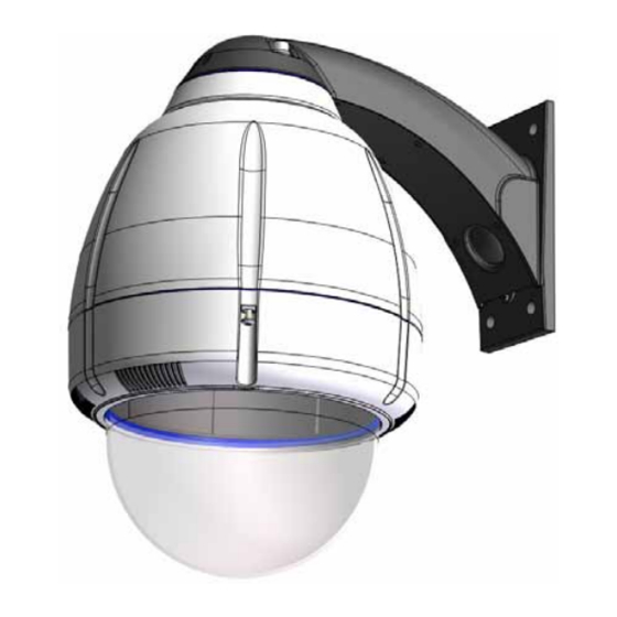
Vandal-Resistant Rugged (Outdoor Dome Housing)
Installation and Operation Instructions for the following models:
RHW75C12N
IP Network Ready 7" Vandal-Resistant Outdoor dome housing with wall mount,
clear dome polycarbonate, 12VDC input (ideal for solar and battery powered
applications), heater/blower, 42vA, for an IP Network PTZ camera.
Before attempting to connect or operate this product, please read these instructions completely.
www.videolarm.com
CERTIFIED
81-IN5318
08-16-2010
Advertisement
Table of Contents

Related Manuals for Moog Videolarm RHW75T12N


Summary of Contents for Moog Videolarm RHW75T12N
- Page 1 © 2009-2010, Moog Videolarm, Inc. All Rights Reserved R H W 7 5 C 1 2 N Vandal-Resistant Rugged (Outdoor Dome Housing) www.videolarm.com Installation and Operation Instructions for the following models: RHW75C12N IP Network Ready 7” Vandal-Resistant Outdoor dome housing with wall mount, clear dome polycarbonate, 12VDC input (ideal for solar and battery powered applications), heater/blower, 42vA, for an IP Network PTZ camera.
- Page 2 IMPORTANT SAFEGUARDS SAFETY PRECAUTIONS Read these instructions. Keep these instructions. CAUTION Heed all warnings RISK OF ELECTRIC SHOCK DO NOT OPEN Follow all instructions. Do not use this apparatus near water. CAUTION: TO REDUCE THE RISK OF Clean only with damp cloth. ELECTRIC SHOCK, DO NOT REMOVE Do not block any of the ventilation openings.
-
Page 3: Limited Warranty
LIMITED WARRANTY FOR VIDEOLARM INC. PRODUCTS VIDEOLARM INC. warrants this Product to be free from defects in material or workmanship,as follows: PRODUCTCATEGORY PARTS LABOR All Enclosuresand Electronics Five (5) Years Five (5) Years Pan/Tilts Three (3) Years **6 months if used in autoscan Three (3) Years **6 months if used in autoscan /tour operation /tour operation... -
Page 4: Electrical Specifications
Electrical Specifications Contents of Box RHW75 Power 12VDC 12 VDC 49 Watts Accessories: Heater: 20 Watts, Blower: 2 Watt Camera Power: (See Camera Specifications): 27 Watts Max Tools Required: .100” Flat Head Screwdriver Phillips Head Screwdriver English 12 VDC 49 Vatios De Accesorios: Calentador: 20 Watts, Blower: 2 Vatio Energía De la Cámara fotográfica De : (Véase Las Especificaciones De la Cámara fotográfica): 27 Vatios... - Page 5 WALL MOUNTING 4”-5” Trim incoming control & power wires to 4”- 5”, Bracket is designed for 45° conduit tting (If using the for either wall or pendent bracket conduit). Run wire into bracket secure to wall. • El soporte se diseña para la guarnición del conducto 45° (si usa el •...
- Page 6 WALL MOUNTING Important Gasket Must be in place 26 Watts COAX (coax wire not supplied) Wiring the dome can be completed by Align large arrows referring to the diagram. • Atar con alambre la bóveda puede ser terminada • Con seguridad soporte del montaje a emparedar. Tire del cableado refiriendo al diagrama.
- Page 7 FOR PENDENT/ WALL MOUNTING 4”-5” Trim incoming control and power wires to 4-5 for Secure lanyard to lanyard clip either wall or pendent bracket • La tapa segura de la cubierta SM5 con mercancías duras • Con seguridad soporte del montaje a emparedar. Tire del cableado a través del soporte y del ojal de la posición según lo demostrado.
- Page 8 Important Gasket Must be in place Align large arrows To lock turn clockwise • Alinee las flechas grandes • Alinee las flechas grandes • Alignez les grandes flèches • Alignez les grandes flèches • Richten Sie große Pfeile aus • Richten Sie große Pfeile aus •...
- Page 9 POWER Power and Control Inputs (Outside of Housing) RJ45 Camera Power (+ 12 VDC) 24VAC Camera Power (- 12 VDC) Orange POWER Camera Max 40 Watts Accessory Power (+12 VDC) Yellow Camera Orange Heater/Blower Yellow Accessory Power (-12 VDC) Green 52 Watts Heater/Blower Green...
- Page 10 Captive Axis 213 (3) #8x3/8” Screw Mounting Plate ½" 1" 2" MOUNTING HOLE MOUNTING HOLE Install the camera to the mounting plate with (2) #10 screws and lock washers provided. Place (3) #8x3/8” screws on the spacers and align the mounting slots. Slide on plate and camera then secure. •...
- Page 11 Axis 215 (3) #8x3/8” Mounting Plate 1" 1" 2" MOUNTING HOLE MOUNTING HOLE Install the camera to the mounting plate using (4) #8 bolts and lock washers. Place (3) #8x3/8” screws on the spacers and line up the mounting slots. Slide plate in and secure. •...
- Page 12 CANON - VB-C10 Captive Screw Mounting Plate (3) #8x3/8” 1" 2" MOUNTING HOLE MOUNTING HOLE Install the camera to the mounting plate with (2) #10 screws and lock washers provided. Place (3) #8x3/8” screws on the spacers and align the mounting slots. Slide on plate and camera then secure. •...
- Page 13 ELMO 400/401 Captive (4) #8x3/8” Screw Mounting Plate 1" 1" 2" MOUNTING HOLE MOUNTING HOLE Attach camera to mounting plate using (4) #8 screws, star washer, and nuts. Complete assembly as shown, then secure camera to the quick release plate. •...
-
Page 14: Jvc-Vn-C655U
JVC-VN625U Captive (4) #8x3/8” Screw Mounting Plate ½" 1" MOUNTING HOLE Attach quick release bracket to mounting plate using (4) #8 screws and star washer. Complete assembly as shown, then secure camera to the quick release adapter. • Una el soporte rápido del lanzamiento a la placa de montaje usando (4) los tornillos #8 y la arandela de la estrella. Termine a asamblea como cámara fotográfica demostrada, después segura a la placa rápida del lanzamiento. - Page 15 Panasonic KX-HCM180 Captive (3) #8x3/8” Screw Mounting Plate ½" 1" 2" MOUNTING HOLE Attach camera bracket to mounting plate using (1) ¼” x 20 bolt, lock washer, and washer. Complete assembly as shown, then secure camera to the quick release plate. •...
- Page 16 Sony RX550 Captive (3) #8x3/8” Screw Mounting Plate ½" No bolt used here MOUNTING HOLE Attach camera to mounting plate using (4) M3 bolts and lock washer. Complete assembly as shown, then secure camera to the quick release plate. • Ate la cámara a la pletina usando (4) los pernos M3 y arandela de cerradura. Termine a la asamblea como se muestra, entonces cámara segura a la placa del lanzamiento rápido.
- Page 17 Sony RZ30 Captive (3) #8x3/8” Screw Mounting Plate ½" 2" MOUNTING HOLE Attach camera to mounting plate using (1) ¼” x 20 bolt, washer, and lock washer. Complete assembly as shown, then secure camera to the quick release plate. • Ate la cámara a la pletina usando (1) perno de x 20 del ¼”, arandela, y arandela de cerradura. Termine a la asamblea como se muestra, entonces cámara segura a la placa del lanzamiento rápido.
-
Page 18: Toshiba Ik-Wb21A
TOA 2564 Captive (4) #8x3/8” Screw Mounting Plate MOUNTING HOLE Attach camera to mounting plate using (4) #8 screws and star washer. Complete assembly as shown, then secure camera to the quick release plate. • Ate la cámara a la pletina usando (4) los tornillos #8 y arandela de la estrella. Termine a la asamblea como se muestra, entonces cámara segura a la placa del lanzamiento rápido. - Page 19 Pixord 261/263 Captive (3) #8x3/8” Screw Mounting Plate ½" 1" MOUNTING HOLE Attach camera bracket to mounting plate using (3) #8 x ⅜” bolts, washer, and nuts. Complete assembly as shown, then secure camera to the quick release plate. • Ate el soporte de la cámara a la pletina usando (3) pernos, arandela, y las tuercas del ⅜ de #8 x los”. Termine a la asamblea como se muestra, entonces cámara segura a la placa del lanzamiento rápido.
- Page 20 Align the arrows on the outside of the dome Connect Lanyard to trim ring assembly. and lock. • Alinee las flechas en el exterior de la bóveda y • Conecte el acollador con el montaje del anillo del trábese.
-
Page 21: Replacement Parts List
Replacement Parts List RHW75 IRHW75 PART NUMBER DESCRIPTION RC7C CLEAR REPLACEMENT CAPSULE 1A RC7T TINTED REPLACEMENT CAPSULE RPRH752 LOWER TRIM RING RPRH7503 DOME CLAMPING RING RPNET02 NETWORK HGS POWER SUPPLY RPFD072 24V HEATER 5A RPFD072/12 12V HEATER (12VDC MODELS ONLY) RPFD080 BLOWER RP40PCMD01... -
Page 22: Product Registration/Warranty
Product Registration/Warranty Thank you for choosing Videolarm. We value your patronage and are solely committed to providing you with only the highest quality products available with unmatched customer service levels that are second- to-none in the security industry. Should a problem arise, rest assure that Videolarm stands behind its products by offering some of the most impressive warranty plans available: 3 Years on all Housings, Poles, Power Supplies, and Accessories and 5 Years on all camera systems (SView, QView, Warriors), and InfraRed Illuminators.
Need help?
Do you have a question about the RHW75T12N and is the answer not in the manual?
Questions and answers