
Related Manuals for Cypress CY3684


Summary of Contents for Cypress CY3684
- Page 1 CY3674/CY3684 ® EZ-USB Development Kit User Guide Doc. # 001-66390 Rev. *D Cypress Semiconductor 198 Champion Court San Jose, CA 95134-1709 Phone (USA): 800.858.1810 Phone (Intnl): 408.943.2600 www.cypress.com...
- Page 2 Cypress Source Code and derivative works for the sole purpose of creating custom soft- ware and or firmware in support of licensee product to be used only in conjunction with a Cypress integrated circuit as speci- fied in the applicable agreement.
-
Page 3: Table Of Contents
Contents 1. Introduction Introduction ........................7 Kit Contents .........................7 1.2.1 Hardware......................7 1.2.2 Software on CD-ROM ..................7 1.2.3 Required Tools Not Included ................8 1.2.4 Other Suggested Tools..................8 Document Revision History ..................8 Documentation Conventions ..................8 2. Getting Started Kit Installation ......................9 Install Hardware......................17 3. - Page 4 5.4.2.6 I2C Routines ..................42 6. Cypress USB Drivers for EZ-USB Kits Cypress USB Signed Driver Package for EZ-USB Devices ........43 Drivers for Firmware Examples and Default EZ-USB Configuration ......44 6.2.1 Binding Cypress USB Driver to EZ-USB Development Board.......45 Drivers for Firmware and Keil Monitor Automatic Download using Script Files..
- Page 5 8.2.2 Method to Download Firmware Image to EZ-USB Internal RAM Memory ..69 8.2.3 Method to Download Firmware Image to External I2C EEPROM....69 8.2.4 Binding Cypress USB Driver for the Downloaded Firmware Image....70 8.2.5 Testing the hid_kb Firmware Example Functionality ........70 IBN Firmware Example ....................71...
- Page 6 Reference Designs ....................105 9.2.1 CY4611B - USB 2.0 to ATA Reference Design ..........105 9.2.2 CY4651 v1.3 - Cypress and AuthenTec Reference Design for Biometric Secu- rity in External USB Hard Disk Drives106 9.2.3 CY3686 NX2LP-FLEX USB 2.0-to-NAND Reference Design Kit ....106 Application Notes.....................106...
-
Page 7: Introduction
1.2.2 Software on CD-ROM EZ-USB firmware library and firmware frameworks ■ Firmware sample code ■ Microsoft-certified signed Cypress generic USB driver (3.4.5.000) for Windows XP, Vista, and 7 ■ OS platforms. Cypress USB class library (CyApi) ■ Cypress USB console ■... -
Page 8: Required Tools Not Included
05/09/2011 NMMA Update to section 2.2 Schematic Summary 06/06/2012 NMMA The document has to be updated with the OOB review comments. Minor text edits. Updated correct path “Start->All programs->Cypress- 06/29/2012 NMMA >Cypress Suite USB 3.4.7-->CyConsole” in the document. 09/27/2013 DBIR Removed Section 7.2.4, Bulkloop Application. -
Page 9: Getting Started
Getting Started This chapter describes the installation of the CY3684 EZ-USB FX2LP DVK software. The process is similar for the CY3674 EZ-USB FX1 DVK. Kit Installation To install the kit software, follow these steps: 1. Insert the kit CD/DVD into the CD/DVD drive of your PC. The CD/DVD is designed to auto-run and the kit installer startup screen appears. - Page 10 Getting Started Figure 2-2. InstallShield Wizard 4. On the Product Installation Overview screen, select the installation type that best suits your requirement. The drop-down menu has three options - Typical, Complete, and Custom, as shown in Figure 2-3. In the current installer, all three installation types result in the same set of software getting installed.
- Page 11 Getting Started 5. When the installation begins, all packages are listed on the Installation page. A green check mark appears adjacent to every package that is downloaded and installed, as shown in Figure 2-4. Wait until all the packages are downloaded and installed successfully. Figure 2-4.
- Page 12 Getting Started Figure 2-5. Keil Welcome Screen 7. Enter the user name and company name credentials, as shown in Figure 2-6, to proceed with the installation. Figure 2-6. Keil User Information lnput Window 8. The Keil software proceeds with the installation and copies the necessary packages at the default directory C:\Keil.
- Page 13 Getting Started Figure 2-7. Keil User Information lnput Window 9. The GPIF designer software is triggered after Keil installation.This software is used to create State machine waveforms to communicate between the EZ-USB device and devices such as FPGA, image sensors, FIFO, and so on. If the software is already installed in the PC, then the installer will not trigger the installation.
- Page 14 If the software is already installed in the PC, then the installer will not trigger the installation. If the PC does not contain the software, then the SuiteUSB welcome screen appears, as shown Figure 2-10. Click Next and accept the Cypress Software license agreement, as shown in Figure 2-11.
- Page 15 Figure 2-12. Click Next. The default directory of the SuiteUSB is C:\Cypress\Cypress Suite USB 3.4.7. The default directory can be changed at this stage. Click Next after selecting the directory. Click the Install button in the subsequent window. The SuiteUSB package installation progress is shown in the next window.
- Page 16 Getting Started Figure 2-12. SuiteUSB User Login Window 13.The CY3684 EZ-USB FX2LP development Kit Finish window appears after installing the kit con- tent, Keil software, GPIF Designer, and the SuiteUSB 3.4.7 package. EZ-USB Development Kit User Guide, Doc. # 001-66390 Rev. *D...
-
Page 17: Install Hardware
Getting Started Figure 2-13. CY3684 Finish Window Note The procedure to install the CY3674 installer is similar to CY3684. Install Hardware No hardware installation is required for this kit. EZ-USB Development Kit User Guide, Doc. # 001-66390 Rev. *D... - Page 18 Getting Started EZ-USB Development Kit User Guide, Doc. # 001-66390 Rev. *D...
-
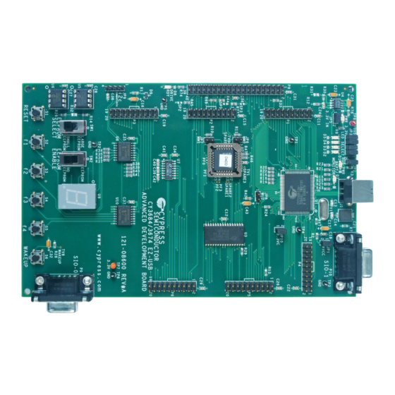
Page 19: Advanced Development Board
USB designs. All ICs on the board operate at 3.3 V. The board can be powered from the USB connector. The EZ-USB Advanced Development Board is supplied as part of the Cypress EZ-USB DVK, which includes an evaluation version of Cypress-customized software development tools from Keil Software Inc. -
Page 20: Jumpers
Advanced Development Board Jumpers Table 3-1. EZ-USB Development Board Jumpers Jumper Function Default Notes Connects 3.3 V power to JP1, JP10 IN (1-2) the EZ-USB chip. Powers the on-board 3.3 V To operate the board in self-powered mode, remove regulator from USB Vbus IN (1-2) JP2 and supply 4 V to 5 V to JP2-1, and GND to a ground pin (TP1 is a convenient GND point). - Page 21 EZ-USB in a manner (using internal VID/PID) that binds the development system board to the Cypress debug tools, such as the Control Panel and Keil. When running, SW2 can be switched to the ON position to allow 8051 access, for example, to reprogram the EEPROM.
-
Page 22: Interface Connectors
Advanced Development Board Note If an EEPROM is connected to the SCL and SDA lines, but does not contain 0xC0 or 0xC2 as its first byte, the loader reverts to the ‘generic’ case. In other words, the bootloader operates as though no EEPROM is connected. - Page 23 Advanced Development Board Table 3-4. Pin Designation (P1) Alternate Default Default Alternate 3.3V PSEN# FD[15] FD[14] FD[13] FD[12] FD[11] FD[10] FD[9] FD[8] FD[7] FD[6] FD[5] FD[4] FD[3] FD[2] FD[1] FD[0] Table 3-5. Pin Designation (P2) Alternate Default Default Alternate 3.3V RDY1 SLWR SLRD...
- Page 24 Advanced Development Board Table 3-7. Pin Designation (P4) Alternate Default Default Alternate 3.3 V CLKOUT PLD2 PLD1 N.C. Table 3-8. Pin Designation (P5) Alternate Default Default Alternate 3.3 V IFCLK Table 3-9. Pin Designation (P6) Alternate Default Default Alternate 3.3 V INT5# INT4 WAKEUP#...
-
Page 25: Ata Connector P8
Advanced Development Board ATA Connector P8 Table 3-10 shows the pinout for P8, a 40-pin connector that interfaces with a standard ATA cable. This is for ATA use only. SP1, 2, and 3 should be bridged with the solder to connect the appropriate pull-up and pull-down resistors required for ATA. -
Page 26: Memory Maps
Advanced Development Board Memory Maps Figure 3-1. Four EZ-USB Development Board Memory Maps Note The GAL sets EA=1 for the Ext Flash configuration only, enabling external code memory. The factory default is to have both MM1 and MM0 jumpers removed. This setting should be used for all development work using the Keil software tools. -
Page 27: I2C Expanders
Advanced Development Board C Expanders U8 and U10 are Philips PCF8574 I/O expanders. They connect to the I C bus SCL and SDA pins, and provide eight GPIO pins. U8 provides eight output bits, connected to the 7-segment readout U9. U10 provides eight input bits: four connect to push buttons S2–S5 and four are uncommitted. -
Page 28: General-Purpose Indicators
Advanced Development Board 3.11 General-Purpose Indicators A portion of the GAL (U2) decodes 8051 reads to certain external memory addresses to turn the four general-purpose indicators D2–D5 on and off. The following figure shows the positions of the four indicator LEDs and a table of the external 8051 addresses, which are read to turn them on and off. The four jumpers above the LEDS must be installed to use this feature. -
Page 29: Development Kit Contents
Windows directory tree as shown in Figure 4-1. The default directory for the CY3674 kit is C:\Cypress\USB\CY3674_EZ-USB_FX1_DVK\ and for the CY3684 kit, it is C:\Cypress\USB\CY3684_EZ-USB_FX2LP_DVK\. In further sections, the default installation directory is referred to as <Installed_directory>, which refers to the default directory of the respective EZ-USB kits. -
Page 30: Documentation
Documentation This directory contains documentation, which describes the EZ-USB DVK. The following table lists the summary of the documents in the CY3674 and CY3684 EZ-USB development kits. Table 4-1. Documents Summary for EZ-USB FX1 and FX2LP Development Kits Kit Specific/ S.No... -
Page 31: Firmware
Development Kit Contents forms. Table 4-2 has the detailed list of drivers. Table 4-2. USB Drivers in EZ-USB Development Kits Driver Package S.No Description Folder This directory contains the generic cyusb.sys driver information file, cyusbfx1_fx2lp.inf, and the Microsoft caltalog file (cyusbfx1_fx2lp.cat) files cyusbfx1_fx2lp required to enumerate the EZ-USB devices.They .INF file contains default Fuse ROM and firmware example VID/PIDs. -
Page 32: Gpif_Designer
EZ-USB development board SuiteUSB This folder contains the SuiteUSB 3.4.7 installer package and a sample Cypress Software License agreement document. The software is installed as part of the EZ-USB Kit installer and the contents are, by default, located at C:\Cypress\Cypress Suite USB 3.4.7.The package contains C++... -
Page 33: Target
Development Kit Contents and C# .NET application tools to communicate with the EZ-USB device. In addition, it contains Cypress generic USB drivers (3.4.7). These are unsigned drivers. Target This directory contains the EZ-USB register definition header files, Keil debug monitor, and so on. - Page 34 Development Kit Contents EZ-USB Development Kit User Guide, Doc. # 001-66390 Rev. *D...
-
Page 35: Ez-Usb Firmware Frameworks
EZ-USB Firmware Frameworks The firmware frameworks simplify and accelerate USB peripheral development using the EZ-USB chip. The frameworks implement the 8051 code for EZ-USB chip initialization, USB standard device request handling, and USB suspend power management services. The user provides a USB descriptor table and code to implement the peripheral function to complete a fully compliant USB device. - Page 36 EZ-USB Firmware Frameworks Figure 5-1. Firmware Frameworks Flowchart EZ-USB Development Kit User Guide, Doc. # 001-66390 Rev. *D...
-
Page 37: Building Frameworks
EZ-USB Firmware Frameworks Building FrameWorks The framework is written using the Keil uVision2 Compiler. It is tested only with these tools. Because the source uses several Keil C extensions, compatibility with other compilers is not guaranteed. For your custom device firmware, you can either start with one of the firmware examples or start with the "clean"... -
Page 38: Function Hooks
EZ-USB Firmware Frameworks Function Hooks The frameworks provides function hooks to simplify the addition of user code. The functions are divided into three categories: those called by the task dispatcher, the standard device request parser, and the USB interrupt handler. The following sections contain a complete list of functions and their descriptions. -
Page 39: Dr_Getinterface()
EZ-USB Firmware Frameworks 5.3.2.2 DR_GetInterface() BOOL DR_GetInterface() This function is called before the frameworks implement the Get Interface device request. The regis- ter array SETUPDAT contains the current eight byte setup command. If TRUE is returned, the frame- works will implement the command. If FALSE is returned, it will do nothing. 5.3.2.3 DR_SetInterface() BOOL DR_SetInterface() -
Page 40: Dr_Vendorcmnd()
EZ-USB Firmware Frameworks 5.3.2.9 DR_VendorCmnd() void DR_VendorCmnd() This function is called when the frameworks determine a vendor specific command has been issued. The register array, SETUPDAT, contains the current eight-byte setup command. This function has no return value. The frameworks does not implement any vendor-specific commands. However, the EZ- USB serial interface engine (SIE) uses vendor-specific command, 0xA0, to implement software uploads and downloads. -
Page 41: Ez-Usb Library
EZ-USB Firmware Frameworks descriptor in response to a get configuration descriptor request and must return its full-speed config- uration descriptor in response to a get other-speed descriptor request. EZ-USB Library The EZ-USB library is an 8051 .LIB file that implements functions that are common to many firmware projects. -
Page 42: Ezusb_Susp()
EZ-USB Firmware Frameworks 5.4.2.4 EZUSB_Susp() void EZUSB_Susp(void) This function suspends the processor in response to a USB suspend event. This function will not return until the suspend is cleared by a USB bus resume or a wake-up event on the EZUSB wake-up pin. -
Page 43: Cypress Usb Drivers For Ez-Usb Kits
EZ-USB (FX1/FX2LP) kits. It also includes the SuiteUSB installer, which supports a collection of USB Host application tools designed in C++ and C# .NET framework. These tools are useful to communicate with any Cypress USB 2.0 device. -
Page 44: Drivers For Firmware Examples And Default Ez-Usb Configuration
Cyxxx.cat - These are Windows catalog files, which contain digital signature. This file indicates ■ that this driver-cyusb.sys passed the Microsoft driver certification process (WHQL). Cyusb.sys - This is the Cypress-provided generic USB driver for all USB 2.0 products.The driver ■ version 3.4.5 is used in the driver certification process Cyxx.INF - This file contains information about the .cat file and .sys file entries. -
Page 45: Binding Cypress Usb Driver To Ez-Usb Development Board
The EZ-USB (FX1/FX2LP) development board supplied with the kit is used to bind the signed Cypress USB driver. Following are the steps to bind the driver: 1. Disconnect the USB A-to-B cable between the J1 connector and the PC USB Host port, if con- nected previously. - Page 46 Cypress USB Drivers for EZ-USB Kits Figure 6-4. Windows Hardware Wizard for Driver Update 7. Select Yes, This time only and click Next. Select Install from a specific location and click Next. 8. In the subsequent window, select Don't search. I will choose driver to install and select Next.
-
Page 47: Drivers For Firmware And Keil Monitor Automatic Download Using Script Files
12.Observe the EZ-USB device in the list of USB device controllers. Following are the strings for the default Fuse ROM VID/PID of EZ-USB devices. a. EZ-USB FX1:“Cypress EZ-USB FX1 No EEPROM(3.4.5.000)” b. EZ-USB FX2LP:“Cypress EZ-USB FX2LP No EEPROM(3.4.5.000)” This completes the entire binding process for the EZ-USB device. The process is similar for any USB device with its own proprietary drivers. -
Page 48: Script File Generation And Play Using Cyconsole
Open the Cyconsole tool located at C:\Cypress\Cypress Suite USB 3.4.7\CyConsole. Click on C:\Cypress\Cypress Suite USB 3.4.7\CyConsole. Alternately, the tool can be accessed at Windows Start > All Programs > Cypress > Cypress SuiteUSB 3.4.7. Follow these steps to generate and play the script. -
Page 49: Script Generation And Play Using Cycontrolcenter
C:\Cypress\Cypress Suite USB 3.4.7\CyConsole. Alternately, the tool can be accessed at Windows Start > All Programs > Cypress >Cypress Suite USB 3.4.7 > CyConsole. Follow these steps to generate and play the script. Figure 6-6. CyControlCenter Script Button Options ... - Page 50 1. CyLoad.cat: These are Windows Catalog files which indicates that the USB driver cyusb.sys passed Microsoft driver certification (WHQL) process. 2. Cyusb.sys: This is the cypress provided generic USB driver for all USB 2.0 products. The driver version 3.4.5 was used in the driver certification process 3.
- Page 51 Cypress USB Drivers for EZ-USB Kits [Device.NTx86] ;%VID_XXXX&PID_XXXX.DeviceDesc%=CyLoad, USB\VID_XXXX&PID_XXXX %VID_04B4&PID_0084.DeviceDesc%=CyLoad, USB\VID_04B4&PID_0084 ;for x64 platforms [Device.NTamd64] ;%VID_XXXX&PID_XXXX.DeviceDesc%=CyLoad, USB\VID_XXXX&PID_XXXX %VID_04B4&PID_0084.DeviceDesc%=CyLoad, USB\VID_04B4&PID_0084 …… [CyLoad] CopyFiles=CyLoadFW.Files AddReg=CyLoad.AddReg [CyLoad.HW] AddReg=CyLoad.AddReg.Guid [CYLoad.Services] Addservice = CyLoad, 2,CyLoad.AddService [CyLoad.NT] CopyFiles=CyLoadFW.Files AddReg=CyLoad.AddReg [CyLoad.NT.HW] AddReg=CyLoad.AddReg.Guid [CyLoad.NT.Services] Addservice = CyLoad,2,CyLoad.AddService ..
-
Page 52: How To Test Cyload Driver Package
[DestinationDirs] section. ■ The Cypress generic USB driver (ver 3.4.5) is also copied in a similar manner to Windows OS System folders defined under [DestinationDirs] section. The VID/PID-0x04B4/0x0084, which is part of the .INF file is linked to Cyload.spt The windows ■... -
Page 53: Keil Debug Monitor Download Using Script And Cymonfx1_Fx2Lp Driver Pack
Suite USB 3.4.7. The Cypress generic USB drivers are located in the Driver\bin folder. The Cypress generic USB drivers (ver 3.4.7) are located in this directory for different Windows OS plat- forms. These are unsigned drivers. For testing the applications provided with SuiteUSB, the Signed... - Page 54 Cypress USB Drivers for EZ-USB Kits EZ-USB Development Kit User Guide, Doc. # 001-66390 Rev. *D...
-
Page 55: Usb Pc Host Utilities And Suiteusb Applications
Utility”. SuiteUSB Applications SuiteUSB tools can be used to communicate with any Cypress USB 2.0 device. The USB driver packages provided are generic Cypress USB drivers (cyusb.sys and cyusbinf). The Suite USB 3.4.7 installer executable is provided in the CD/DVD under the SuiteUSB folder with respect to the CD/ DVD root directory. -
Page 56: Cyconsole Utility
FxEEPROM -NA- programming can also be done using CyConsole or CyControlCenter The C++ applications use CyAPI.lib to communicate with the Cypress USB device.The C# .NET framework applications use CyUSB.dll to communicate with the hardware. 7.2.1 Cyconsole Utility The Cyconsole performs tasks, such as firmware download to EZ-USB RAM, Small EEPROM (16 bytes, and Large EEPROM (32 KB). - Page 57 Figure 7-1. CyConsole Main Window Snapshot Figure 7-1 displays the connected Cypress USB 2.0 device (FX2LP, in this case) and its attributes, such as USB class, and the list of endpoints it supports. Prior to firmware download, the Record Script button on the top left corner is used to record the entire download process, including the firmware binary embedded inside it.
- Page 58 Vend_ax Example on page 91 Iso Trans: This button is used to transfer data over Isochronous IN/OUT endpoints. After the ■ Cystream firmware example is downloaded (CYStream.hex) from C:\Cypress\Cypress Suite USB 3.4.7\Firmware\CyStreamer, this button is used to send data over Isochro- nous IN/OUT endpoints...
-
Page 59: Cycontrolcenter Utility
OUT endpoints using the Bulk Trans button. A sample demonstration is provided in the section Bulkloop Example on page 77. For more details on Cyconsole, refer to CyConsole.chm and CyConsole.pdf at C:\Cypress\Cypress Suite USB 3.4.7\CyConsole. A sample demon- stration of this utility, while using firmware examples, is provided in the section EZ-USB Develop- ment Kit Firmware Examples chapter on page FileTrans: This button is used to download raw packet data to the EZ-USB device.The sample... -
Page 60: Streamer Utility
Script Generation and Play using CyControlCenter on page Data transfers: Using the tool, the USB packet data can be transferred over an endpoint. The ■ procedure is explained in the CyControlCenter.pdf file located at C:\Cypress\Cypress Suite USB 3.4.7\CyUSB.NET\. 7.2.3 Streamer Utility The Streamer utilities are available in both C++ and C#.NET framework versions. - Page 61 Queue parameters and verify the throughput for different Bulk and Isochronous endpoints across dif- ferent alternate interfaces. 2.Streamer using C# .NET CYUSB.dll: The throughput can also be measured using this utility available at C:\Cypress\Cypress Suite USB 3.4.7\CyUSB.NET\examples\Streamer\bin\Release. EZ-USB Development Kit User Guide, Doc. # 001-66390 Rev. *D...
-
Page 62: Cydesc Utility
Note The maximum data allowed per transfer is 64 KB for Bulk and Isochronous transfers. 7.2.4 Cydesc Utility The utlity is used to view the USB device descriptor of Cypress USB 2.0 devices. The following fig- ure shows the EZ-USB FX2LP device’s default device descriptor. Figure 7-6. Cydesc Display of EZ-USB FX2LP Device Descriptor... -
Page 63: Fxeeprom Utility
USB PC Host Utilities and SuiteUSB Applications 7.2.5 FxEEPROM Utility The utlity is used to program the .iic file to either small EEPROM-U6 or Large4 EEPROM-U5 on the EZ-USB development board. Figure 7-7. FXEEPROM Utility Display The EZ-USB development board is connected to the Windows PC Host in the NO EEPROM mode (SW2 to NO EEPROM side). - Page 64 USB PC Host Utilities and SuiteUSB Applications EZ-USB Development Kit User Guide, Doc. # 001-66390 Rev. *D...
-
Page 65: Ez-Usb Development Kit Firmware Examples
Keil uVision2 IDE. Table 8-1 lists the firmware examples pro- vided with the kit, along with their brief description. Table 8-1. List of Firmware Example in EZ-USB Development Kits (CY3674/CY3684) S.No Firmware Example Description... -
Page 66: Method To Verify The Firmware Example Functionality
EZ-USB Development Kit Firmware Examples Method to Verify the Firmware Example Functionality The firmware examples provided with the kit can be verified using the EZ-USB development board provided with the kit. There are different types of firmware download mechanisms for the EZ-USB devices. -
Page 67: Building Firmware Example Code For Ez-Usb Internal Ram And External Ee
EZ-USB Development Kit Firmware Examples lowing table summarizes the mapping of Push buttons on the FX2LP development board to key- board buttons. Table 8-2. Function Mapping of Development Board Buttons EZ-USB Development Board Function Push Button Shift Send ‘a’ Send ‘b’ Send ‘c’... - Page 68 EZ-USB Development Kit Firmware Examples Figure 8-2. Build Window Snapshot of hid_kb Project Note Observe that the total Code bytes of the hid_kb project is less than the 4-k code limit of Keil uVision2 IDE provided along with the kit. Firmware for EZ-USB RAM memory: The output of the Build Target is hid_kb.hex.
-
Page 69: Method To Download Firmware Image To Ez-Usb Internal Ram Memory
<Installed_directory>\<Version>\Firm- ware\hid_kb 6. After download, the image does not require a Cypress USB driver for testing the 4-button virtual keyboard functionality. The complete functionality is handled by the Microsoft Windows OS native HID drivers. -
Page 70: Binding Cypress Usb Driver For The Downloaded Firmware Image
Binding Cypress USB Driver for the Downloaded Firmware Image The hib_kb project contains firmware for a HID-class keyboard device (Interface class: HID = 03 and subclass = 00) and uses the Microsoft native HID driver, instead of Cypress generic USB driver. 8.2.5 Testing the hid_kb Firmware Example Functionality The EZ-USB development board enumerates as a human interface device (HID). -
Page 71: Ibn Firmware Example
EZ-USB Development Kit Firmware Examples IBN Firmware Example 8.3.1 Description This example illustrates the configuration of EZ-USB to accept bulk data from the host and loop it back to the host using an IN-BULK-NAK interrupt. Click on the ibn.Uv2 project file at <Installed_directory>\<Version>\Firmware\ibn. - Page 72 EZ-USB Development Kit Firmware Examples and 4 are armed to accept data from the host. This data is transferred to endpoint 6 and endpoint 8 respectively. To implement this, endpoint 2 is first checked to see if it has data. This is done by read- ing the endpoint 2 empty bit in the endpoint status register (EP2468STAT).
-
Page 73: Building Firmware Example Code For Ez-Usb Ram And Eeprom
Binding Cypress USB Driver for the Downloaded Firmware Image The IBN project uses vendor-class (0xFF) with VID/PID-0x04B4/1004.This example should bind with the Cypress generic USB driver, cyusb.sys, and the driver information file, cyusbfx1_fx2lp.inf, which contains the relevant VID/PID of this example. Follow the procedure outlined in... -
Page 74: Pingnak Firmware Example
EZ-USB Development Kit Firmware Examples 3. On sending a packet to these endpoints when both the buffers are full, the endpoints NAK the transfer because there is no space available. If an IN transfer is requested on either EP6 or EP8, the corresponding In-Bulk-NAK interrupt is asserted and data is transferred from EP2 to EP6 or from EP4 to EP8. - Page 75 EZ-USB Development Kit Firmware Examples interrupts and enables the PING-NAK interrupt for EP2 and EP4. The loopback is implemented in the TD_Poll() function that is called repeatedly when the device is idle. Endpoints 2 and 4 are armed to accept data from the host. This data is transferred to endpoint 6 and endpoint 8 respectively. To implement this, endpoint 2 is first checked to see if it has data.
-
Page 76: Building Firmware Example Code For Ez-Usb Ram And Eeprom
Binding Cypress USB Driver for the Downloaded Firmware Image The pingnak project uses vendor-class (0xFF) with VID/PID-0x04B4/1004. This example should bind with the Cypress generic USB driver, cyusb.sys, and the driver information file, cyusbfx1_fx2lp.inf, which contains the relevant VID/PID of this example. Follow the procedure out-... -
Page 77: Bulkloop Example
EZ-USB Development Kit Firmware Examples near Bulk Trans button of EZ-USB interface window, enter the length as 512 and HexBytes as 5, and then press the Bulk Trans button. 2. This data can be read back from Endpoint 6 using CyConsole. For example, select Endpoint 6 IN in the pipe, enter the length as 512, and then press the Bulk Trans button. - Page 78 EZ-USB Development Kit Firmware Examples EP4BCL = 0x80;// arm EP4OUT by writing byte count w/skip. SYNCDELAY; EP4BCL = 0x80; The above lines arm the two OUT endpoints by skipping two packets of data making the buffers available to receive OUT data. AUTOPTRSETUP |= 0x01;...
-
Page 79: Building Bulkloop Firmware Example Code For Ez-Usb Ram And Eeprom
EZ-USB Development Kit Firmware Examples After the data is transferred, endpoint 2 has to be 'rearmed' to accept a new packet from the host. Endpoint 6 has to be 'committed', that is, make the FIFO buffers available to the host for reading data from endpoint 6. -
Page 80: Binding Cypress Usb Driver For The Downloaded Firmware Image
Binding Cypress USB Driver for the Downloaded Firmware Image The Bulkloop firmware uses vendor class (0xFF) with VID/PID-0x04B4/1004. This example should bind with Cypress generic USB driver cyusb.sys and driver information file cyusbfx1_fx2lp.inf, which contains the relevant VID/PID of this example. Follow the procedure outlined in section... -
Page 81: Test Using Cybulk Application
The Bulkloop firmware can be tested using this C++ application. For 32-bit Windows OS the CyBulk can be accessed at C:\Cypress\Cypress Suite USB 3.4.7\CyAPI\examples\cybulk\x86\Release. The 64-bit version of Cybulk application is located at C:\Cypress\Cypress Suite USB 3.4.7\CyAPI\examples\cybulk\x64\Release. Select EZ-USB device in the drop down menu and also select anyone the Bulk Endpoint pairs- EP2/EP6 or EP4/EP8. -
Page 82: Testing Bulkloop Example Using Bulkloop C# .Net Application
The Bulkloop firmware can be tested using the Bulkloop C# .NET application, which is located at Start > All Programs > Cypress > Cypress SuiteUSB 3.4.7 > Bulkloop. Select the Bulkloop OUT and Bulkloop IN endpoint pairs EP2 and EP6, or EP4 or EP8. Click Start and observe the number of successful Bulk IN and Bulk OUT Transfers Figure 8-8. -
Page 83: Bulksrc Firmware Example
EZ-USB Development Kit Firmware Examples Bulksrc Firmware Example 8.6.1 Description This project illustrates the configuration of EZ-USB device to accept bulk data from the host and loop it back to the host. Click on bulksrc.Uv2 located at <Installed_directory>\<Ver- sion>\Firmware\Bulksrc and observe the code. Five endpoints are configured in the TD_init() function of bulksrc.c to handle bulk transfer: Two OUT (EP2/EP4) endpoints and two IN (EP6/EP8) endpoints are double-buffered pairs. - Page 84 EZ-USB Development Kit Firmware Examples SYNCDELAY; EP2BCL = 0x80; Endpoint EP6 is re-armed with an incremental pattern of data starting with 0x2. // if EP6 IN is available, re-arm it If(!(EP2468STAT & bmEP6FULL)) SYNCDELAY; EP6BCH = 0x02; SYNCDELAY; EP6BCL = 0x00; The contents received from the EP4 OUT endpoint are copied to a temporary buffer, myBuffer[], and re-armed.
-
Page 85: Building Bulksrc Firmware Example Code For Ez-Usb Ram Memory And Ee- Prom85
Testing the Bulksrc Firmware Functionality The Bulksrc firmware functionality can be tested using the CyConsole utility. Following are the steps Open the CyConsole PC application from Start > All Programs > Cypress > Cypress Suit- ■ eUSB 3.4.7 > CyConsole. -
Page 86: Bulkext Firwmare Example
EZ-USB Development Kit Firmware Examples Figure 8-9. Bulk IN Data Transfer on EP6 Endpoint Select the EP4 and EP8 pairs and repeat the same procedure as mentioned above. Observe that ■ the data transferred on EP4 is exactly looped back to EP8. Internally, the loopback is performed through a temporary buffer (myBuffer [512]). -
Page 87: Building Bulkext Firmware Example Code For Ez-Usb Ram Memory And Ee- Prom87
EZ-USB Development Kit Firmware Examples AUTOPTRL2 = 0x00; count = (EP2BCH << 8) + EP2BCL; for( i = 0x0000; i < count; i++ ) EXTAUTODAT2 = EXTAUTODAT1; // Source is external RAM APTR1H = 0x28; APTR1L = 0x00; // Destination is EP6IN AUTOPTRH2 = MSB( &EP6FIFOBUF );... -
Page 88: Method To Download Firmware Image To Ez-Usb Internal Ram And Eeprom
Binding Cypress USB Driver for the Downloaded Firmware Image The Bulkext firmware uses vendor-class (0xFF) with VID/PID-0x04B4/1004. This example should bind with the Cypress-generic USB driver, cyusb.sys, and driver information file, cyusbfx1_fx2lp.inf which contains the relevant VID/PID of this example. Follow the procedure outlined in... -
Page 89: Testing The Ep_Interrupts Firmware Functionality
EZ-USB Development Kit Firmware Examples 8.8.5 Testing the EP_Interrupts Firmware Functionality The example firmware should be tested in a similar manner as the Bulkloop example.The Bulk data transfers on EP1 are tested with a length of 64 bytes and 512 bytes for the EP2, EP4, EP6, and EP8. The process is similar to the one outlined in Testing the Bulkloop Firmware Functionality on page iMemtest Firmware Example... -
Page 90: Extr_Intr Firmware Example
EZ-USB Development Kit Firmware Examples 8.12 extr_intr Firmware Example This example is used to demonstrate the use of external interrupts INT0, INT1, INT4, INT5, and INT6. The relevant interrupt service routines (ISR) for each of these external interrupts were pro- vided in isr.c. -
Page 91: Testing The Example
INT1/ INT4/ INT5/ INT6, PC.1 and D3/ PC.4 and D4/ PC.5 and D5/ PC.6 are toggled. Port C pin toggling can be checked by connecting those pins to the DSO. Table 8-4. Port Pins and External Interrupt Mapping Port/Jumper name on Pin Name CY3684/CY3674 Port C LEDs INT0 P2.19 INT1 P2.18... -
Page 92: Testing The Vend_Ax Example
EZ-USB Development Kit Firmware Examples Located at <Installed_directory>\<version\Firmware/vend_ax and observe the vendor commands implemented in the C routine - DR_VendorCmnd (void). Following are the vendor com- mands defined in the vend_ax.c file: Table 8-5. Vendor Command Definitions in vend_ax Example Vendor Command/Macro S.No Function... - Page 93 EZ-USB Development Kit Firmware Examples Figure 8-11. A2 Vendor Command Write Operation using Cyconsole b. Test using CyControlCenter To read the contents of small EEPROM, select Direction = In, Req Type = vendor, Target = Device, Bytes to Transfer = 8 bytes (data to read), and Req Code = 0xA2 for reading the data on control endpoint.
- Page 94 EZ-USB Development Kit Firmware Examples 2. 0xA3 command-Download data to RAM memory This command is used to download data to either the EZ-USB internal (0x0000-0x3FFFF) RAM or the external RAM memory. a. Test using CyControlCenter To write the contents to RAM memory, select Direction = OUT, Req Type = vendor, Target = Device, Bytes to Transfer = 8 bytes (data to read), and Req Code = 0xA3, and enter data to send as C2 B4 04 84 00 01 00 11 in the Data to send box.
- Page 95 Figure 8-16. A6 Vendor Command using CyControlCenter 4. 0xA8 command-EZ-USB This command is used to disconnect and re-connect the EZ-USB IC using the CPUCS register. The EZ-USB re-enumerates. Observe the Cypress device disappearing from the CyControlCen- ter window and re-appearing in the same window. Figure 8-17 summarizes the command trigger using CyControlCenter.
- Page 96 EZ-USB Development Kit Firmware Examples Figure 8-18. A9 Vendor Command Operation using CyControlCenter 6. 0xAA/0xAB-Setting I2C interface frequency Using this command, the I2C interface frequency can be set to 100 kHz or 400 kHz. Figure 8-19 summarizes the command trigger using CyControlCenter. Figure 8-19.
-
Page 97: Debugging Using Keil Monitor Program
3. Connect the USB A-to-B cable between the J1 connector and Windows PC Host controller. Con- nect a UART cable between SIO-1 and Windows PC. 4. Follow the process outlined in Binding Cypress USB Driver to EZ-USB Development Board on page 45 to bind the CyMonfx1_fx2lp driver package at <Installed_directory>\<Ver- sion>\Drivers\CyMonfx1_fx2lp.The driver files for the relevant Windows OS can be cho-... - Page 98 EZ-USB Development Kit Firmware Examples e. mon-int-sio0.hex/ mon-int-sio1.hex: This Keil debug monitor file resides in internal EZ-USB RAM memory for corresponding SIO-0 and SIO-1 UART ports. f. mon-int-sio0.spt/mon-int-sio1.spt: This Keil debug monitor script file resides in internal EZ- USB RAM memory for corresponding SIO-0 and SIO-1 UART ports. The debug monitor script file mon-ext-sio1-c0.spt is renamed as mon.spt and used as the default debug monitor script file.
- Page 99 EZ-USB Development Kit Firmware Examples Figure 8-22. Serial Ports List in Device Manager Window 10.Click on Project > Options for Target 'Target1’ in Keil µVision2 IDE and select the Debug Tab in the new pop-up window as shown in Figure 8-23 Figure 8-24.
- Page 100 EZ-USB Development Kit Firmware Examples Figure 8-24. Fig 7-24: Debug Tab window in Project options 11. Select the settings under Keil Monitor-51 Driver and select the relevant COM port for the UART cable connected to SIO-1 port as shown in Figure 8-25 Figure 8-26.
- Page 101 EZ-USB Development Kit Firmware Examples Figure 8-27. Debug Session Trigger in Keil uVision2 IDE 14.The IDE switches to the Debug mode; a yellow arrow indicates the Program Counter location in the Disassembly window of dev_io project. Figure 8-28. Disassembly View of dev_io.c file in Keil uVision2 IDE ...
- Page 102 EZ-USB Development Kit Firmware Examples Figure 8-30. Enabling Debug Toolbar View in Keil 18.Set a breakpoint by selecting the first line in the "case KEY_F2" section (which is in file dev_io.c). To set or remove a breakpoint, double-click the line or right-click on the line as and select Insert/Remove Breakpoint shown in Figure 8-31.
- Page 103 EZ-USB Development Kit Firmware Examples 19.A red breakpoint indication is seen in the margin next to the new breakpoint as shown in Figure 8-32. Press the RUN button as shown in Figure 8-33. Figure 8-32. Breakpoint Indicator in Keil uVision2 IDE ...
- Page 104 EZ-USB Development Kit Firmware Examples EZ-USB Development Kit User Guide, Doc. # 001-66390 Rev. *D...
-
Page 105: Resources
Resources Hardware Resources The CY3674/CY3684 development kit has several hardware resources that guide you in designing your own custom board. The documents in the hardware directory of the DVK kit software are: CY3674_PCBA_BOM.xls/CY3684_PCBA_BOM.xls: This document lists all the vendor hard- ■... -
Page 106: Cy4651 V1.3 - Cypress And Authentec Reference Design For Biometric Secu
AN1168 - High-speed USB PCB Layout Recommendations This application note details guidelines for designing, controlled-impedance; high-speed USB printed circuit boards to comply with the USB specification. This note is applicable to all Cypress high-speed USB solutions. Some Cypress high-speed USB chips have separate application... - Page 107 ■ AN57322 - Interfacing SRAM with FX2LP over GPIF This application note discusses how to connect Cypress SRAM CY7C1399B to FX2LP over the General Programmable Interface (GPIF). It describes how to create read and write waveforms using the GPIF Designer. This application note is also useful as a reference to connect FX2LP to other SRAMs.
- Page 108 8051 concept. When this program is run, you should be able to light the seven-seg- ment LED on the FX2LP Development Board (CY3684) with a 0-9 count, and control the step rate (1s - 5s) using BULK OUT endpoint transfers from the EZ-USB Control Panel.
- Page 109 Vendor commands are used to issue commands to a device, by which tasks unique to an applica- tion are accomplished. This application note demonstrates how you can quickly design USB ven- dor commands to perform specific features of products. In addition, using the Cypress CyConsole utility to issue vendor commands is also explained.
- Page 110 Resources EZ-USB Development Kit User Guide, Doc. # 001-66390 Rev. *D...
-
Page 111: Appendix
Appendix U2 (GAL) code (file is 'FX2LP.ABL') MODULE fx2lp " Swapped dipswitch settings 00 and 10 on 4-3-98 to allow the all-switchon default x,c,z = .X.,.C.,.Z.; "Inputs A12,A13,A14,A15 pin 11,12,13,16; A11 pin 4; nRD,nPSEN,CLKOUT pin 6,5,2; mm1,mm0 pin 9,7; "Outputs EA,nRAMOE,nRAMCE pin 21,25,27;... - Page 112 ELSE WHEN(modesw == 11) THEN" Ext P&D mem at 0000 and 8000 !nRAMCE = 1; !nRAMOE= !nRD # !nPSEN; EA = 0; ELSE WHEN(modesw == 10) THEN" All program mem external !nRAMCE = 1; !nRAMOE =!nRD # !nPSEN; EA = 1; test_vectors ([mm1,mm0,A15,nRD,nPSEN] ->...
-
Page 113: Board Layout
Board Layout EZ-USB Development Kit User Guide, Doc. # 001-66390 Rev. *D... -
Page 114: Schematic
0805 0805 The only difference between the CY3674 and CY3684 kits is the Cypress EZ-USB part. While the development board of the CY3674 kit includes FX1 (128-pin package), the CY3684 kit has FX2LP. All other components and layout are similar to the CY3684 kit board. -
Page 115: Frequently Asked Questions
A1: Make sure the hardware works well enough to run the tutorial. After software installation, plug in a development board; go through the DVK tutorial. The tutorial is located in the EZ-USB DVK User Guide, which is found in the Start menu under Cypress > USB > Help. The tutorial is short and worthwhile. - Page 116 Q12: Please provide details about the environment setup. A12: If you install into the default directory, <Installed_directory>\<Version> then you can build and debug examples with the Keil uV2 project files provided. The project files have hard-coded paths in them; installing to a different, non-default directory location breaks these project files. Also, there are build.bat files for the projects in the Example folders.
- Page 117 Mouser Electronics Authorized Distributor Click to View Pricing, Inventory, Delivery & Lifecycle Information: Cypress Semiconductor CY3674...
Need help?
Do you have a question about the CY3684 and is the answer not in the manual?
Questions and answers