
Related Manuals for Cypress CY4531 EZ-PD CCG3 EVK


Summary of Contents for Cypress CY4531 EZ-PD CCG3 EVK
- Page 1 CY4531 EZ-PD™ CCG3 Evaluation Kit Guide Doc. No. 002-10218 Rev. *C Cypress Semiconductor 198 Champion Court San Jose, CA 95134-1709 www.cypress.com...
- Page 2 Cypress is not liable, in whole or in part, and you shall and hereby do release Cypress from any claim, damage, or other liability arising from or related to all Unintended Uses of Cypress products.
-
Page 3: Table Of Contents
1.3.1 Recommended Cables and Adapters ....................... 8 Acronyms................................8 Kit Installation ................................10 CY4531 EZ-PD CCG3 EVK Kit Software Installation ..................10 CY4531 EZ-PD CCG3 EVK Hardware Details ......................14 CCG EVK Base Board ............................15 3.1.1 Block Diagram ............................15 3.1.2... - Page 4 Contents Appendix ..................................35 Terminology ................................. 35 CCG3 EVK Base Board ............................36 6.2.1 Schematics ............................. 36 6.2.2 Gerber Files ............................41 6.2.3 Bill of Materials ............................47 CCG3 EVK Daughter Card ..........................52 6.3.1 Schematics ............................. 52 6.3.2 Gerber Files ............................55 6.3.3 Bill of Materials ............................
- Page 5 If such interference is detected, suitable mitigating measures must be taken. The CY4531 EZ-PD CCG3 EVK as shipped from the factory has been verified to meet with requirements of CE as a Class A product.
- Page 6 General Safety Instructions ESD Protection ESD can damage boards and associated components. Cypress recommends that the user perform procedures only at an ESD workstation. If an ESD workstation is not available, use appropriate ESD protection by wearing an antistatic wrist strap attached to the chassis ground (any unpainted metal surface) on the board when handling parts.
-
Page 7: Introduction
USB 2.0 Type-A to Mini-B Cable Quick Start Guide 1.1.1 Hardware Not Included With Kit The CY4531 EZ-PD CCG3 EVK does not come with all of the hardware needed to perform the demonstrations documented in sections SuperSpeed USB Demo,... -
Page 8: Getting Started
CCG3 EVK. Depending on the display monitor you have, use item 3, 4 or 5 in Table 1-1 to connect from the USB Type-C port of the CY4531 EZ-PD CCG3 EVK to the display monitor itself. Use item 6 to run the Dead Battery Demo. - Page 9 Introduction Acronym Definition integrated circuit inter-integrated circuit integrated development environment light-emitting diode ® Programmable Systems-on-Chip PSoC pulse-width modulation quad flat no-lead (package) serial wire debug UART universal asynchronous receiver transmitter upstream facing port Universal Serial Bus USB PD Universal Serial Bus Power Delivery XRES External Reset I/O Pin CY4531 EZ-PD™...
-
Page 10: Kit Installation
To install the kit software, follow these steps: Download the latest kit software setup file “CY4531 EZ-PD CCG3 EVK Complete Setup” from the kit’s website: www.cypress.com/CY4531. This package contains the kit hardware files and the kit documentation (User Guide, Quick Start Guide, and Release Notes). - Page 11 Installation Figure 2-2. Installation Wizard Accept the license agreement for the software components and click Next (Figure 2-3). Figure 2-3. License Agreement CY4531 EZ-PD™ CCG3 Evaluation Kit Guide, Doc. No. 002-10218 Rev. *C...
- Page 12 Installation Figure 2-4 shows the installation progress. Figure 2-4. Installation Progress Click Finish when complete (Figure 2-5). Figure 2-5. Software Installation Complete CY4531 EZ-PD™ CCG3 Evaluation Kit Guide, Doc. No. 002-10218 Rev. *C...
- Page 13 Click the Check for updates button at the bottom of the window. If “No Updates” appears adjacent to the CY4531 EZ-PD CCG3 EVK, click the Exit button. If there are updates, click the Update button to download and install the latest kit package.
-
Page 14: Cy4531 Ez-Pd Ccg3 Evk Hardware Details
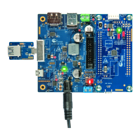
Details The CY4531 EZ-PD CCG3 EVK consists of a base board and a daughter card. The CCG3 device is mounted on the daughter card, which is connected to the base board to evaluate the CCG3 device’s Type-C port functionality as shown in Figure 3-1. -
Page 15: Ccg Evk Base Board
CCG3 EVK Hardware Details CY4531 EZ-PD 3.1 CCG EVK Base Board The CCG EVK base board is an evaluation board equipped with a Type-C port, a SuperSpeed USB Type-B port, and a Display Port interface. It is primarily intended as a demonstration board for notebook designs that house a Type-C connector. -
Page 16: Connectors And Jumper Settings
CCG3 EVK Hardware Details CY4531 EZ-PD 3.1.3 Connectors and Jumper Settings Figure 3-3 shows the CCG EVK base board connectors and default settings of the jumpers. Table 3-2 contains the detailed description of the connectors and jumper settings. Figure 3-3: CCG EVK Base Board Connectors SuperSpeed Consumer DisplayPort... - Page 17 CCG3 EVK Hardware Details CY4531 EZ-PD Connector/Jumper Description Default Pin 3,4: Power from VBUS of Type-C Connector (Type-C_VBUS) Pin 5,6: Regulated output power to 20-Vdc terminal (J7) from USB_C_PWR pin of CCG3 daughter card Pin 7: GND Pin 8: GND Pin 9: I2C_SCL Pin 10: VBUS_DISCHRG Pin 11: I2C_SDA...
-
Page 18: Cy4531 Ccg3 Daughter Card
USB 2.0 Mini-B receptacle connected to USB-to-Serial device C interface C pins and interrupt output pin for connecting to an Embedded Controller (EC) Programming SWD pins to debug/program CCG3 using Cypress MiniProg3 CY4531 EZ-PD™ CCG3 Evaluation Kit Guide, Doc. No. 002-10218 Rev. *C... -
Page 19: Connectors And Jumper Settings
CCG3 EVK Hardware Details CY4531 EZ-PD Feature Description 5 V from USB 2.0 Mini (Connector J7 of CCG3 daughter card) 5 V from MiniProg3 (Connector J1 of CCG3 daughter card) Power 5 V to 20 V from Type-C connector (Connector J3 of CCG base board) 24V DC from DC Power Supply Connector (Connector J1 of CCG base board) 3.2.3 Connectors and Jumper Settings Figure 3-5... -
Page 20: Powering The Cy4531 Ez-Pd Ccg3 Evk Setup
3.3 Powering the CY4531 EZ-PD CCG3 EVK Setup The CY4531 EZ-PD CCG3 EVK can be powered by connecting the 24-V DC power adapter to connector J1 of the CCG EVK base board. LED1 on both the boards glow green and LED2 on the base board blinks orange continuously, to indicate a successful power connection. -
Page 21: Programming The Ccg3 Device On Cy4531 Ccg3 Evk
(SDK) (version 2.2 or later) along with PSoC allows users to harness the capabilities of Cypress’s CCG families of Type-C Controllers. It provides a Type-C and USB-PD specification compliant firmware stack along with the necessary drivers and software interfaces required to implement applications using CCG controllers. - Page 22 Launch the EZ-PD Configuration Utility as shown in . After the installation, the EZ-PD Configuration Utility is available at the following location by default: Windows > Start > All Programs > Cypress > EZ-PD Configuration Utility > EZ-PD Configuration Utility Figure 4-2: EZ-PD Configuration Utility Select Tools >...
- Page 23 CCG3 EVK Programming the CCG3 Device on CY4531 Figure 4-3: Upgrading CCG3 Firmware CCG3’s internal device flash contains two copies of firmware that can mutually update each other. These copies are called FW1 and FW2, and are designed to be placed at different flash locations. If the CCG3 device is currently running FW1, only FW2 can be updated and vice-versa.
- Page 24 CCG3 EVK Programming the CCG3 Device on CY4531 Table 4-1. Possible “Firmware Update” options based on CCG3 device status and user selection Firmware Update with “Bootloader Firmware Update with Firmware Status Flashing” unchecked “Bootloader Flashing” checked FW1 and FW2 Invalid Can update FW1, FW2 or both* Only FW1 valid Can update FW2 only...
- Page 25 A MiniProg3 device (not provided with the kit) is required to perform SWD programming. The MiniProg3 device can be purchased on the Cypress website (click here). Warning: Do not disconnect the EVK from the PC while the firmware update is in progress.
-
Page 26: Kit Operation
The SuperSpeed USB demonstration provides details about connecting a host (PC) to a client (USB flash drive) through the CY4531 EZ-PD CCG3 EVK boards, also referred to as the “SuperSpeed USB Demo” in this kit guide. The DisplayPort demonstration provides details about connecting a host (PC) to a client (display monitor) through the CY4531 EZ-PD CCG3 EVK boards, also referred to as the “DisplayPort Demo”... - Page 27 2-3 positions respectively. Mount the CCG3 daughter card on the CCG base board of the CY4531 EZ-PD CCG3 EVK if not already mounted. Use the SuperSpeed USB Type-A to Type-B cable to connect the CCG base board to the PC.
-
Page 28: Explanation Of Functionality
Operation Connect the 24-V DC power adapter provided with the kit to the CY4531 EZ-PD CCG3 EVK base board power jack J1. Observe LED1 on the CCG3 daughter card and CCG base board glow green to indicate power is ON, and LED2 on CCG base board blinks orange to indicate the CCG firmware is executing. -
Page 29: Displayport Demo
Mount the CCG3 daughter card on the CCG base board of the CY4531 EZ-PD CCG3 EVK if not already mounted. Connect the 24-V DC power adapter provided with the kit to the CY4531 EZ-PD CCG3 EVK base board power jack J1. -
Page 30: Common Problems And Troubleshooting
If the demo is not functional, follow these guidelines to troubleshoot: Ensure that the CY4531 EZ-PD CCG3 EVK’s base board and daughter card are powered by verifying that LED1 on both boards is glowing green and LED2 on the CCG base board is blinking. If LED2 on CCG base board is not blinking, CCG3 device is not active. -
Page 31: Boards, Cables, And Accessories Needed
Mount the CCG3 daughter card on the CCG base board of the CY4531 EZ-PD CCG3 EVK if not already mounted. Do not connect the 24V DC power adapter provided with the kit to the power jack J1 of the CCG base board. -
Page 32: Power Supply Connections
Type-C port can be charged from the dead battery condition. 5.3.3 Power Supply Connections A PC with a USB 3.0 port and a DisplayPort, along with the CY4531 EZ-PD CCG3 EVK, is equivalent to a PD-enabled Type-C port Notebook as shown in Figure 5-6. -
Page 33: Common Problems And Troubleshooting
Type-C power adapter is connected to the Type-C port. In a CY4531 EZ-PD CCG3 EVK enabled Type-C PC design, the entire EVK can be powered using the following methods: Method 1: A DC power adapter is connected to the DC power jack (J1) on CCG base board. In this scenario, the CCG3 device turns on the power provider control circuitry and power is available on the power input headers. - Page 34 Operation Ensure that the CY4531 EZ-PD CCG3 EVK’s base board and daughter card are powered by verifying that LED1 on both boards is glowing green and LED2 on the CCG base board is blinking. If LED2 on CCG base board is not blinking, CCG3 device is not active.
-
Page 35: Appendix
6. Appendix 6.1 Terminology This guide assumes that the user of the CCG3 board is familiar with the fundamentals of Type-C connectivity and the USB Power Delivery protocol. A brief description of Type-C terms is provided here for reference. Alternate Modes: A feature of a USB Type-C system whereby one or both of the SuperSpeed lanes may be repurposed for use with a different serial protocol, such as a DisplayPort, eSATA, or Thunderbolt. -
Page 36: Ccg3 Evk Base Board
Appendix 6.2 CCG3 EVK Base Board 6.2.1 Schematics CY4531 EZ-PD™ CCG3 Evaluation Kit Guide, Doc. No. 002-10218 Rev. *C... - Page 37 Appendix CY4531 EZ-PD™ CCG3 Evaluation Kit Guide, Doc. No. 002-10218 Rev. *C...
- Page 38 Appendix CY4531 EZ-PD™ CCG3 Evaluation Kit Guide, Doc. No. 002-10218 Rev. *C...
- Page 39 Appendix CY4531 EZ-PD™ CCG3 Evaluation Kit Guide, Doc. No. 002-10218 Rev. *C...
- Page 40 Appendix CY4531 EZ-PD™ CCG3 Evaluation Kit Guide, Doc. No. 002-10218 Rev. *C...
-
Page 41: Gerber Files
Appendix 6.2.2 Gerber Files CY4531 EZ-PD™ CCG3 Evaluation Kit Guide, Doc. No. 002-10218 Rev. *C... - Page 42 Appendix CY4531 EZ-PD™ CCG3 Evaluation Kit Guide, Doc. No. 002-10218 Rev. *C...
- Page 43 Appendix CY4531 EZ-PD™ CCG3 Evaluation Kit Guide, Doc. No. 002-10218 Rev. *C...
- Page 44 Appendix CY4531 EZ-PD™ CCG3 Evaluation Kit Guide, Doc. No. 002-10218 Rev. *C...
- Page 45 Appendix CY4531 EZ-PD™ CCG3 Evaluation Kit Guide, Doc. No. 002-10218 Rev. *C...
- Page 46 Appendix CY4531 EZ-PD™ CCG3 Evaluation Kit Guide, Doc. No. 002-10218 Rev. *C...
-
Page 47: Bill Of Materials
6.2.3 Bill of Materials Item Qty Reference Value Description Manufacturer Mfr Part Number 600- PCB,3.18X3.71" CAF resistant Cypress 600-60271-01 60271-01 High Tg ENIG finish,6 layer, Color Approved = BLUE, Silk = WHITE. Manufacturer C25,C26 0.01uF CAP CER 10000PF 25V 10% X7R... - Page 48 Appendix Item Qty Reference Value Description Manufacturer Mfr Part Number SMBJ24A TVS DIODE 24VWM 50VC STMicroelectroni SMBJ24A-TR DO214AA D11,D12,D13,D14,D16,D ESD105B TVS DIODE 5.5VWM 14VC Infineon ESD105B102ELE 102EL TSLP2-2 Technologies 6327XTMA1 SMBJ24C TVS DIODE 24VWM 38.9VC SMB Vishay SMBJ24CA- A-E3/52 Semiconductor E3/52 Diodes Division MMSZ47...
- Page 49 Appendix Item Qty Reference Value Description Manufacturer Mfr Part Number MMBT39 TRANS NPN 40V 0.2A SOT23 MMBT3904LT1G 04LT1 Semiconductor NTMFS5 MOSFET N-CH 40V 13A SO-8FL NTMFS5834NLT 834NL Semiconductor NTTFS58 MOSFET N-CH 60V 8A 8-WDFN NTTFS5826NLTA 26NL Semiconductor R111,R124,R166,R168 RES SMD 0.0OHM JUMPER Panasonic ERJ-3GEY0R00V 1/10W 0603...
- Page 50 CD74HC238PWR 238PWR TSSOP Instruments PS8740B USB Type-C Redriving Switch for Parade PS8740B USB Host / DisplayPort Source Technologies CY7C652 IC USB TO UART BRIDGE DUAL Cypress CY7C65215- 32QFN Semiconductor 32LTXI USBLC6- TVS DIODE 5.25VWM 17VC STMicroelectroni USBLC6-2P6 SOT666 RT8299A IC REG BUCK ADJ 3A SYNC...
- Page 51 SCREW, Pan Head, machined screws, M2 x 5mm Jumper Plug 2.54MM JUMPER PLUG WITH Wurth 609002115121 TEST POINT Electronics Label LBL, PCA Identification Label, Cypress Vendor Code, Datecode, Serial Semiconductor Number(YYWWVVXXXX) No load components PMEG30 DIODE SCHOTTKY 30V 5A PMEG3050BEP,1 50BEP,11 SOD128...
-
Page 52: Ccg3 Evk Daughter Card
Appendix 6.3 CCG3 EVK Daughter Card 6.3.1 Schematics CY4531 EZ-PD™ CCG3 Evaluation Kit Guide, Doc. No. 002-10218 Rev. *C... - Page 53 Appendix CY4531 EZ-PD™ CCG3 Evaluation Kit Guide, Doc. No. 002-10218 Rev. *C...
- Page 54 Appendix CY4531 EZ-PD™ CCG3 Evaluation Kit Guide, Doc. No. 002-10218 Rev. *C...
-
Page 55: Gerber Files
Appendix 6.3.2 Gerber Files CY4531 EZ-PD™ CCG3 Evaluation Kit Guide, Doc. No. 002-10218 Rev. *C... - Page 56 Appendix CY4531 EZ-PD™ CCG3 Evaluation Kit Guide, Doc. No. 002-10218 Rev. *C...
- Page 57 Appendix CY4531 EZ-PD™ CCG3 Evaluation Kit Guide, Doc. No. 002-10218 Rev. *C...
- Page 58 Appendix CY4531 EZ-PD™ CCG3 Evaluation Kit Guide, Doc. No. 002-10218 Rev. *C...
- Page 59 Appendix CY4531 EZ-PD™ CCG3 Evaluation Kit Guide, Doc. No. 002-10218 Rev. *C...
- Page 60 Appendix CY4531 EZ-PD™ CCG3 Evaluation Kit Guide, Doc. No. 002-10218 Rev. *C...
-
Page 61: Bill Of Materials
6.3.3 Bill of Materials Item Qty Reference Value Description Manufacturer Mfr Part Number 600-60327- PCB,3.56X1.66" CAF resistant Cypress Approved 600-60327-01 High Tg ENIG finish,6 layer, Manufacturer Color = BLUE, Silk = WHITE. 10uF CAP CER 10UF 50V X7R 1210 Murata Electronics GRM32ER71H10... - Page 62 EVQ-PE105K PE105K 0.05A 12V Electronic Components TYPE-C_VBUS_P1 TEST POINT PC MINI .040"D Keystone 5000 Electronics CYPD3125- EZ-PD CCG3 - USB Type-C Cypress CYPD3125- 40LQXIT Port Controller Semiconductor 40LQXIT AP2822AK IC USB POWER SWITCH Diodes Incorporated AP2822AKATR- ATR-G1 SOT25 CY7C65215 IC USB TO UART BRIDGE...
-
Page 63: Revision History
Revision History Document Revision History Document Title: CY4531 EZ-PD™ CCG3 Evaluation Kit Guide Document Number: 002-10218 Revision Issue Date Origin of Description of Change Change 02/19/2016 New EVK user guide. 06/23/2016 Added schematics, gerber layouts, & bill of materials for the CCG3 base board and daughter card.
Need help?
Do you have a question about the CY4531 EZ-PD CCG3 EVK and is the answer not in the manual?
Questions and answers