
Related Manuals for GORMAN-RUPP PUMPS PA6H60-4045H FT4-ESP


Summary of Contents for GORMAN-RUPP PUMPS PA6H60-4045H FT4-ESP
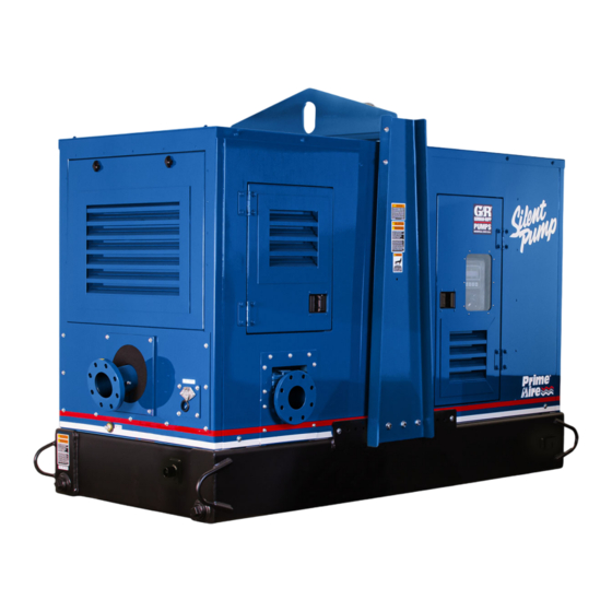
- Page 1 OM-07149-01 December 29, 2017 INSTALLATION, OPERATION, AND MAINTENANCE MANUAL WITH PARTS LIST PA SERIES PUMP MODEL PA6H60‐4045H FT4‐ESP GORMAN‐RUPP PUMPS www.grpumps.com 2017 Gorman‐Rupp Pumps Printed in U.S.A.
- Page 2 Register your new Gorman‐Rupp pump online at www.grpumps.com Valid serial number and e‐mail address required. The engine exhaust from this product contains chemicals known to the State of California to cause cancer, birth defects or other reproductive harm. RECORD YOUR PUMP MODEL AND SERIAL NUMBER Please record your pump model and serial number in the spaces provided below.
-
Page 3: Table Of Contents
TABLE OF CONTENTS INTRODUCTION ..........PAGE I - 1 SAFETY ‐... - Page 4 TABLE OF CONTENTS (continued) PERIODIC CHECKS ............PAGE C - 4 Seal Cavity And Bearing Lubrication .
-
Page 5: Introduction
PA SERIES OM-07149 INTRODUCTION Thank You for purchasing a Gorman‐Rupp pump. HAZARD AND INSTRUCTION Read this manual carefully to learn how to safely DEFINITIONS install and operate your pump. Failure to do so could result in personal injury or damage to the The following are used to alert maintenance per... -
Page 6: Safety - Section A
PA SERIES OM-07149 SAFETY ‐ SECTION A This information applies to Prime Aire cable before performing any mainte Series pumps. Refer to the manual ac nance. Failure to do so may result in se companying the engine before attempt rious personal injury. ing to begin operation. - Page 7 OM-07149 PA SERIES certain that the pump and all piping or hose connections are tight, properly supported and secure before operation. Do not operate the pump without guards in place over the rotating parts. Ex posed rotating parts can catch clothing, fingers or tools, causing severe injury to personnel.
-
Page 8: Installation - Section B
127.93 69.71 [ 3249,4 ] APPROX APPROX [ 1770,7 ] Figure 1. Pump Model PA6H60-4045H FT4-ESP PREINSTALLATION INSPECTION a. Inspect the pump for cracks, dents, damaged threads, and other obvious damage. The pump assembly was inspected and tested be b. Check for and tighten loose attaching hard... -
Page 9: Battery Installation
OM-07149 PA SERIES c. Carefully read all tags, decals, and markings good working condition and of suffi on the pump assembly, and perform all duties cient capacity and that they are posi indicated. Note that the pump shaft rotates in tioned so that loads will be balanced the required direction. -
Page 10: Suction And Discharge Piping
PA SERIES OM-07149 only; however, the engine manufacturer should be pump performance. Seal the gauge threads with consulted for continuous operation at angles pipe dope to ensure an airtight seal. Follow the greater than 15 sealant manufacturer's recommendations when selecting and applying the pipe dope. The pipe dope should be compatible with the liquid being SUCTION AND DISCHARGE PIPING pumped. -
Page 11: Sealing
OM-07149 PA SERIES ommendations when selecting and applying the of one or both pumps. To avoid this, position the pipe dope. The pipe dope should be compatible suction inlets so that they are separated by a dis with the liquid being pumped. tance equal to at least 3 times the diameter of the suction pipe. -
Page 12: Discharge Lines
PA SERIES OM-07149 Refer to the information which follows for installa DISCHARGE LINES tion details for the liquid level sensing system pro vided with your pump. Siphoning Float Switch Installation Do not terminate the discharge line at a level lower than that of the liquid being pumped unless a si... -
Page 13: Float Switch Installation
OM-07149 PA SERIES ENGINE (0.9) CONTROL (.76) (Emptying) (0.6) (Filling) (.46) OPERATING (0.3) RANGE CABLE (See Table Below) TETHER (.15) POINT (Emptying) (0.3) (0.6) (0.9) (1.2) APPROXIMATE FREE CORD LENGTH IN FT. (M) 1.25” Pipe (Filling) (Not Furnished) Figure 3. Float Switch Data COLD WEATHER INSTALLATION from the line that runs between the top of the prim... - Page 14 OM-07149 PA SERIES OPERATION - SECTION C Review all SAFETY information in Section A. cated (see LUBRICATION in MAINTENANCE AND REPAIR). Follow the instructions on all tags, labels and The pump will begin to prime upon startup. The air decals attached to the pump. in the suction line will be discharged from the educ...
-
Page 15: Operation - Section C
OM-07149 PA SERIES AL'. After the engine starts and the unit is fully Adjust the engine speed to achieve the desired primed, adjust the engine RPM until the desired output. Do not exceed the factory set engine speed flow rate is achieved. and system operating pressure. -
Page 16: Automatic Starting
OM-07149 PA SERIES connections or fittings. Keep all line connections Strainer Check and fittings tight to maintain maximum pump effi ciency. Check the strainer regularly, and clean it as neces sary. The strainer should also be checked if pump flow rate begins to drop. Monitor and record the vacuum suction gauge readings regularly to detect Pump Vacuum Check strainer blockage. -
Page 17: Strainer Check
OM-07149 PA SERIES Safety Shutdown System PERIODIC CHECKS Seal Cavity And Bearing Lubrication The unit is equipped with a safety system to auto matically shut down the engine under certain con Both the seal and bearing cavities were fully lubri ditions. -
Page 18: Troubleshooting - Section D
OM-07149 PA SERIES the drain port and preventing the pump from com COLD WEATHER PRESERVATION pletely draining, insert a rod or stiff wire in the drain port, and agitate the liquid during the draining If the pump will be idle for an extended period of process. - Page 19 OM-07149 PA SERIES TROUBLESHOOTING - SECTION D Review all SAFETY information in Section A. 5. Close the suction and discharge valves. 6. Vent the pump slowly and cau tiously. 7. Drain the pump. Before attempting to open or service the pump: 1.
-
Page 20: Preventive Maintenance
OM-07149 PA SERIES TROUBLE POSSIBLE CAUSE PROBABLE REMEDY Check strainer and clean if neces Strainer clogged. PUMP STOPS OR FAILS TO DELIVER sary. RATED FLOW OR Check and clean check valve. Discharge check valve clogged. PRESSURE (cont.) Suction intake not submerged at Check installation and correct proper level or sump too small. - Page 21 OM-07149 PA SERIES TROUBLE POSSIBLE CAUSE PROBABLE REMEDY BEARINGS RUN Bearing temperature is high, but Check bearing temperature regu TOO HOT within limits. larly to monitor any increase. Low or incorrect lubricant. Check for proper type and level of lubricant. Suction and discharge lines not prop...
- Page 22 OM-07149 PA SERIES Preventive Maintenance Schedule Service Interval* Item Daily Weekly Monthly Semi‐ Annually Annually General Condition (Temperature, Unusual Noises or Vibrations, Cracks, Leaks, Loose Hardware, Etc.) Pump Performance (Gauges, Speed, Flow) Bearing Lubrication Seal Lubrication (And Packing Adjustment, If So Equipped) V‐Belts (If So Equipped) Air Release Valve Plunger Rod (If So Equipped) Front Impeller Clearance (Wear Plate)
- Page 23 OM-07149 PA SERIES PUMP MAINTENANCE AND REPAIR - SECTION E MAINTENANCE AND REPAIR OF THE WEARING PARTS OF THE PUMP WILL MAINTAIN PEAK OPERATING PERFORMANCE. STANDARD PERFORMANCE FOR PUMP MODEL PA6H60‐4045H FT4‐ESP Based on 70_F (21_C) clear water at sea level with minimum suction lift.
- Page 24 OM-07149 PA SERIES PARTS PAGE ILLUSTRATION 12 16 11 16 30 11 16 Figure 1. Pump Model PA6H60-4045H FT4-ESP PAGE E - 2 MAINTENANCE & REPAIR...
- Page 25 OM-07149 PA SERIES Pump Model PA6H60-4045H FT4-ESP PARTS LIST (From S/N 1681776 Up) ITEM PART NAME PART ITEM PART NAME PART NUMBER NUMBER PUMP END ASSY 46133-370 BULKHEAD FITTING 26381-295 HARD FIBER FLAT WSHR 21163-201 JD PWR UNIT 4045H FT4...
- Page 26 PA SERIES ILLUSTRATION GREEN WIRE GREEN WIRE BLACK WIRE BLACK WIRE RED WIRE SILVER PIN SOCKET RED WIRE WHITE WIRE WIRING DETAIL SILVER PIN SOCKET WHITE WIRE Figure 2. Pump Model PA6H60-4045H FT4-ESP (cont'd) PAGE E - 4 MAINTENANCE & REPAIR...
- Page 27 OM-07149 PA SERIES Pump Model PA6H60-4045H FT4-ESP PARTS LIST (From S/N 1681776 Up) ITEM PART NAME PART ITEM PART NAME PART NUMBER NUMBER PUMP END ASSY 46133-370 BULKHEAD FITTING 26381-295 HARD FIBER FLAT WSHR 21163-201 JD PWR UNIT 4045H FT4...
- Page 28 OM-07149 PA SERIES ILLUSTRATION Figure 3. Pump End Assembly PAGE E - 6 MAINTENANCE & REPAIR...
- Page 29 OM-07149 PA SERIES Pump End Assembly PARTS LIST ITEM PART PART NAME NUMBER PUMP SUB ASSEMBLY 46133-408 CHECK VALVE KIT 6" 48274-015 -CHECK VALVE 26642-134 -FLAPPER 26688-001 -GASKET 26688-002 -O‐RING 25152-377 PRIMING CHAMBER KIT 48275-005 PUMP SUPPORT BRACKET 34266-047 15080 HEX HEAD CAP SCREW B1206 15991 LOCK WASHER...
- Page 30 OM-07149 PA SERIES ILLUSTRATION Figure 4. Pump Sub Assembly PAGE E - 8 MAINTENANCE & REPAIR...
- Page 31 OM-07149 PA SERIES PARTS LIST Pump Sub Assembly ITEM PART PART NAME NUMBER REPAIR PUMP CASING ASSY SEE NOTE BELOW ROTATING ASSEMBLY 44163-502 HEX HEAD CAP SCREW B0604-1/2 17000 LOCK WASHER J06 17090 WEAR PLATE 38691-864 11010 O‐RING 25152-453 PIPE PLUG P08 15079 VENTED PIPE PLUG 4823A 15079...
- Page 32 OM-07149 PA SERIES ILLUSTRATION SEAL AREA DETAIL Figure 5. Repair Rotating Assembly PAGE E - 10 MAINTENANCE & REPAIR...
- Page 33 OM-07149 PA SERIES PARTS LIST Repair Rotating Assembly ITEM PART PART NAME NUMBER IMPELLER 38615-095 11010 2.25 DIA. SEAL ASSEMBLY 46512-149 BALL BEARING 23422-019 BEARING HOUSING 38251-513 10000 VENTED PIPE PLUG 4823A 15079 AIR VENT S1530 REDUCER PIPE BUSHING AP0802 15079 BALL BEARING 23422-414 DRIVE FLANGE...
- Page 34 OM-07149 PA SERIES ILLUSTRATION Figure 6. Priming Chamber Kit PARTS LIST ITEM PART PART NAME NUMBER PRIMING CHAMBER ASSY 46112-709 PIPE BUSHING AP1608 15070 STREET ELBOW RS08 11999 BALL VALVE 26631-052 STUD C0809 15991 HEX NUT D08 15991 LOCK WASHER J08 15991 GASKET 38687-053 19060...
- Page 35 OM-07149 PA SERIES ILLUSTRATION Figure 7. Priming Chamber Assembly PARTS LIST ITEM PART PART NAME NUMBER PRIMING VALVE 26664-007 -ORIFICE BUTTON 26688-021 HEX HD CAPSCREW B0806 15991 LOCKWASHER J08 15991 PRIMING VALVE GASKET 38683-657 19060 PRIMING CHAMBER 38343-020 10000 STRAINER ASSY 46641-222 17000 INDICATES PARTS RECOMMENDED FOR STOCK MAINTENANCE &...
- Page 36 OM-07149 PA SERIES ILLUSTRATION Figure 8. Drive Assembly PARTS LIST ITEM PART PART NAME NUMBER COUPLING ASSEMBLY 44165-016 BUSHING 24131-498 24113-603 DRIVE FLANGE 38545-004 10000 LOCKWASHER 21171-536 SOC HD CAPSCREW BD0606 1/2 15991 SOC HD CAPSCREW 22644-220 HEX HD CAPSCREW B0605 15991 HEX HD CAPSCREW 22645-164...
- Page 37 OM-07149 PA SERIES PUMP AND SEAL DISASSEMBLY the owner/maintenance personnel to ensure that only safe, established main AND REASSEMBLY tenance procedures are used, and that any procedures not addressed in this Review all SAFETY information in Section A. manual are performed only after estab Follow the instructions on all tags, label and de...
- Page 38 OM-07149 PA SERIES Discharge Check Valve Removal and NOTE Disassembly When appropriate recycling facilities are available, the user should recycle components and fluids (Figure 3) when doing any routine maintenance / repairs and also at the end of the pump’s useful life. All other Remove the hardware (not shown) securing the components and fluids shall be disposed of ac...
- Page 39 OM-07149 PA SERIES gine. Disconnect the discharge piping from the Install the shaft key (10) in the shaft keyway. Install pump casing. a lathe dog on the drive end of the shaft (11) with the “V” notch positioned over the shaft key. Remove the hardware (7 and 8) securing the drive With the impeller rotation still blocked, see Figure 9 flange (4) to the engine bellhousing.
- Page 40 OM-07149 PA SERIES dowel or other suitable tool to press on the back charge hoses and piping must be re side of the stationary seat until the seat and O‐ring moved from the pump before lifting. Lift can be removed. the pump or component only as high as necessary and keep personnel away Remove the seal plate O‐ring (34).
- Page 41 OM-07149 PA SERIES Shaft and Bearing Reassembly and Installation be replaced any time the shaft and bear ings are removed. (Figure 5) Clean the bearing housing, shaft and all compo Inspect the shaft for distortion, nicks or scratches, nent parts (except the bearings) with a soft cloth or for thread damage on the impeller end.
- Page 42 OM-07149 PA SERIES movement has occurred, use a suitably sized Lubricate the bearings as indicated in LUBRICA sleeve and a press to reposition the bearings TION at the end of this section. against the shaft shoulders. Securing Bearing Housing And Drive If heating the bearings is not practical, use a suit...
- Page 43 OM-07149 PA SERIES 242' or equivalent to the threads of the hardware (7 Clean the seal cavity and shaft with a cloth soaked and 8), and secure the outer ring of the coupling to in fresh cleaning solvent. Inspect the stationary the engine flywheel by torquing the hardware to 45 seat bore in the seal plate for dirt, nicks and burrs, ft.
- Page 44 OM-07149 PA SERIES RETAINER SEAL PLATE SPRING O‐RINGS IMPELLER SLEEVE O‐RING IMPELLER SHIMS IMPELLER SHAFT INTEGRAL SHAFT ROTATING SLEEVE ELEMENT BELLOWS SPRING CENTERING WASHER STATIONARY SEAT DRIVE BAND Figure 10. Seal Assembly clean as required before proceeding with seal installation. Lubricate the shaft sleeve (29) with a small amount This seal is not designed for operation at of light oil and slide the rotating subassembly (con...
- Page 45 OM-07149 PA SERIES Lubricate the O‐rings (6 and 13) with light grease and install them in the grooves in the wear plate and back cover. The shaft and impeller threads must be Clearance between the impeller and wear plate is adjusted using the four back cover nuts (18) and completely clean before reinstalling the im...
- Page 46 OM-07149 PA SERIES adjusting screws so the holes in the collars for the Install the cover O‐ring and secure the cover with locking screws align approximately with the holes the previously removed hardware. in the cover plate. Apply a small amount of light grease to the gasket Loosen the back cover nuts used to press the back to hold it in place and position it against the pump cover into the pump casing one full turn.
- Page 47 OM-07149 PA SERIES cation can cause the bearings to over‐heat, result LUBRICATION ing in premature bearing failure. (Figure 5) Under normal conditions, drain the bearing hous Seal Assembly ing once each year and refill with clean oil. Change the oil more frequently if the pump is operated con Fill the seal cavity through the hole for the vented tinuously or installed in an environment with rapid plug (5) with SAE No.
- Page 48 For Warranty Information, Please Visit www.grpumps.com/warranty or call: U.S.: 419-755-1280 Canada: 519-631-2870 International: +1-419-755-1352 GORMAN‐RUPP PUMPS...
Need help?
Do you have a question about the PA6H60-4045H FT4-ESP and is the answer not in the manual?
Questions and answers