GORMAN-RUPP PUMPS PA Series Installation, Operation And Maintenance Manual
Hide thumbs
Also See for PA Series:
Table of Contents
Advertisement
Quick Links
U
OM−05360−OE02
May 28, 2004
Rev. A 05-21-07
INSTALLATION, OPERATION,
AND MAINTENANCE MANUAL
WITH PARTS LIST
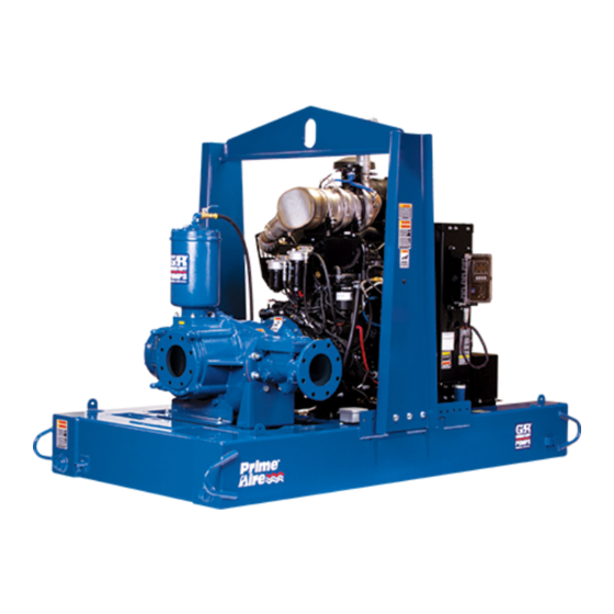
PA SERIES PUMP
MODEL
PA12A60−B−6068T /S1
THE GORMAN-RUPP COMPANY D MANSFIELD, OHIO
D
GORMAN-RUPP OF CANADA LIMITED
ST. THOMAS, ONTARIO, CANADA
Printed in U.S.A
www.grpumps.com.
E
Copyright by the Gorman-Rupp Company
Advertisement
Table of Contents

Subscribe to Our Youtube Channel
Related Manuals for GORMAN-RUPP PUMPS PA Series


Summary of Contents for GORMAN-RUPP PUMPS PA Series
- Page 1 OM−05360−OE02 May 28, 2004 Rev. A 05-21-07 INSTALLATION, OPERATION, AND MAINTENANCE MANUAL WITH PARTS LIST PA SERIES PUMP MODEL PA12A60−B−6068T /S1 THE GORMAN-RUPP COMPANY D MANSFIELD, OHIO GORMAN-RUPP OF CANADA LIMITED ST. THOMAS, ONTARIO, CANADA Printed in U.S.A www.grpumps.com. Copyright by the Gorman-Rupp Company...
- Page 2 Register your new Gorman-Rupp pump online at www.grpumps.com Valid serial number and e-mail address required. The engine exhaust from this product contains chemicals known to the State of California to cause cancer, birth defects or other reproductive harm. RECORD YOUR PUMP MODEL AND SERIAL NUMBER Please record your pump model and serial number in the spaces provided below.
-
Page 3: Table Of Contents
TABLE OF CONTENTS INTRODUCTION ..........PAGE I −... - Page 4 TABLE OF CONTENTS (continued) PARTS LIST: Pump Model ............PAGE E −...
-
Page 5: Introduction
Gor- man-Rupp pump. This pump is a PA Series, priming-assisted centrif- ugal model. The unit is designed for handling non- Immediate hazards which WILL result in volatile, non-flammable liquids containing speci- fied entrained solids. -
Page 6: Safety - Section A
PA SERIES OM−05360 SAFETY - SECTION A This information applies to Prime Aire damage the pump or endanger person- Series pumps. Refer to the manual ac- nel as a result of pump failure. companying the engine or power source before attempting to begin oper- ation. - Page 7 OM−05360 PA SERIES heated pump. Vapor pressure within the pump can cause parts being disen- gaged to be ejected with great force. Al- low the pump to cool completely before Do not operate an internal combustion servicing. engine in an explosive atmosphere.
-
Page 8: Installation − Section Bpage B
PA SERIES OM−05360 INSTALLATION − SECTION B Review all SAFETY information in Section A. configuration, and priming must be tailored to the specific application. Since the pressure supplied Since pump installations are seldom identical, this to the pump is critical to performance and safety,... -
Page 9: Battery Installation
OM−05360 PA SERIES c. Carefully read all tags, decals, and markings POSITIONING PUMP on the pump assembly, and perform all duties indicated. Note that the pump shaft rotates in the required direction. Use lifting and moving equipment in good repair and with adequate capacity to prevent injuries to personnel or dam- age to equipment. -
Page 10: Suction And Discharge Piping
PA SERIES OM−05360 the brake and blocking the wheels before attempt- lines are used, they should have adequate support ing to operate the pump. to secure them when filled with liquid and under pressure. Gauges The pump is drilled and tapped for installing dis- If the pump has been mounted on a mov- charge pressure and vacuum suction gauges. -
Page 11: Sealing
OM−05360 PA SERIES Sealing air to escape from the liquid before it is drawn into the suction inlet. Since even a slight leak will affect priming, head, If two suction lines are installed in a single sump, and capacity, especially when operating with a... -
Page 12: Discharge Lines
PA SERIES OM−05360 Figure 2. Recommended Minimum Suction Line Submergence vs. Velocity DISCHARGE LINES Siphoning If the application involves a high discharge head, gradually close the discharge Do not terminate the discharge line at a level lower than that of the liquid being pumped unless a si- throttling valve before stopping the pump. -
Page 13: Float Switch Installation
OM−05360 PA SERIES Float Switch Installation pipe is available, attach the float switch cable to the standpipe in the sump at the approxi- The Float Switch autostart system employs either a mate desired liquid level. single or double float switch, where a bulb raises or lowers (floats) with the liquid level, thus activating b. -
Page 14: Operation − Section C
OM−05360 PA SERIES OPERATION − SECTION C Review all SAFETY information in Section A. cated (see LUBRICATION in MAINTENANCE AND REPAIR). Follow the instructions on all tags, labels and The pump will begin to prime upon startup. The air decals attached to the pump. -
Page 15: Automatic Starting
OM−05360 PA SERIES AL’. After the engine starts and the unit is fully Liquid Temperature And Overheating primed, adjust the engine RPM until the desired The maximum liquid temperature for this pump is flow rate is achieved. 160_ F (71_C). Do not apply it at a higher operating temperature. -
Page 16: Stopping
OM−05360 PA SERIES vacuum suction gauge readings regularly to detect normal for bearings, and they can operate safely to strainer blockage. at least 180_F (82_C). Checking bearing temperatures by hand is inaccu- Never introduce air or steam pressure into the rate. -
Page 17: Troubleshooting − Section D
OM−05360 PA SERIES TROUBLESHOOTING − SECTION D Review all SAFETY information in Section A. Before attempting to open or service the pump: 1. Familiarize yourself with this manual. 2. Shut down the engine and discon- nect the positive battery cable to en- sure that the pump will remain inop- erative. - Page 18 OM−05360 PA SERIES TROUBLE POSSIBLE CAUSE PROBABLE REMEDY Check strainer and clean if neces- Strainer clogged. PUMP STOPS OR FAILS TO DELIVER sary. RATED FLOW OR Check and clean check valve. Discharge check valve clogged. PRESSURE (cont.) Suction intake not submerged at Check installation and correct proper level or sump too small.
-
Page 19: Preventive Maintenance
OM−05360 PA SERIES TROUBLE POSSIBLE CAUSE PROBABLE REMEDY BEARINGS RUN Bearing temperature is high, but Check bearing temperature regu- TOO HOT within limits. larly to monitor any increase. Low or incorrect lubricant. Check for proper type and level of lubricant. - Page 20 OM−05360 PA SERIES Preventive Maintenance Schedule Service Interval* Item Daily Weekly Monthly Semi- Annually Annually General Condition (Temperature, Unusual Noises or Vibrations, Cracks, Leaks, Loose Hardware, Etc.) Pump Performance (Gauges, Speed, Flow) Bearing Lubrication Seal Lubrication (And Packing Adjustment, If So Equipped)
-
Page 21: Pump Maintenance And Repair - Section E
OM−05360 PA SERIES PUMP MAINTENANCE AND REPAIR − SECTION E MAINTENANCE AND REPAIR OF THE WEARING PARTS OF THE PUMP WILL MAINTAIN PEAK OPERATING PERFORMANCE. STANDARD PERFORMANCE FOR PUMP MODEL PA12A60−B−6068T /S1 Based on 70_F (21_C) clear water at sea level Contact the Gorman-Rupp Company to verify per- formance or part numbers. - Page 22 OM−05360 PA SERIES PARTS PAGE SECTION DRAWING Figure 1. Pump Model PA12A60−B−6068T /S1 PAGE E − 2 MAINTENANCE & REPAIR...
- Page 23 OM−05360 PA SERIES PARTS LIST Pump Model PA12A60−B−6068T /S1 (From S/N 1365606 up) If your pump serial number is followed by an N", your pump is NOT a standard production model. Contact the Gorman-Rupp Company to verify part numbers. ITEM...
- Page 24 OM−05360 PA SERIES SECTION DRAWING Figure 2. Pump Sub-Assembly PAGE E − 4 MAINTENANCE & REPAIR...
- Page 25 OM−05360 PA SERIES PARTS LIST Pump Sub-Assembly ITEM PART NAME PART MAT’L ITEM PART NAME PART MAT’L NUMBER CODE NUMBER CODE PUMP ASSEMBLY PA12A60−B /S1 HOSE CLAMP 26518−641 −−− STREET ELBOW RS16 11999 MALE CONNECTOR 26523−463 −−− BALL VALVE 26631−054 −−−...
- Page 26 OM−05360 PA SERIES SECTION DRAWING Figure 3. Pump Sub-Assembly PAGE E − 6 MAINTENANCE & REPAIR...
- Page 27 OM−05360 PA SERIES PARTS LIST Pump Sub-Assembly ITEM PART MAT’L PART NAME NUMBER CODE TOP GUARD 34263−009 15120SP FLANGED HD CAPSCREW 21634−505 −−− THREAD INSERT 21769−156 −−− HEX HD CAPSCREW B0709 15991 LOCK WASHER 15991 DISTRIBUTION BLOCK 38346−616 10000 GASKET 26813−908...
- Page 28 OM−05360 PA SERIES SECTION DRAWING Figure 4. Pump Model Assembly PAGE E − 8 MAINTENANCE & REPAIR...
- Page 29 OM−05360 PA SERIES PARTS LIST Pump Model Assembly ITEM PART MAT’L PART NAME NUMBER CODE PUMP ASSMEBLY 612M60−B /S1 −−− PRIMING CHAMBER ASSY 46112−707 −−− FLANGE GASKET 4991G 18000 HEX HD CAPSCREW B1413 15991 LOCKWASHER 15991 HEX NUT 15991 12" CHECK VALVE 26642−128...
- Page 30 OM−05360 PA SERIES SECTION DRAWING DRIVE END VIEW Figure 5. 612M60−B /S1 Pump Model Assembly PAGE E − 10 MAINTENANCE & REPAIR...
- Page 31 OM−05360 PA SERIES PARTS LIST 612M60−B /S1 Pump Model Assembly ITEM PART NAME PART MAT’L ITEM PART NAME PART MAT’L NUMBER CODE NUMBER CODE PUMP CASING 38219−305 10010 IMPELLER WASHER 31167−022 15030 SOC HD CAPSCREW BD1206 15990 IMP/WEAR RING ASSY 46151−022...
- Page 32 OM−05360 PA SERIES SECTION DRAWING Figure 6. 46112−707 Priming Chamber Assembly ITEM PART MAT’L PART NAME NUMBER CODE PRIMING VALVE 26664−007 −−− −ORIFICE BUTTON 26688−021 −−− HEX HD CAPSCREW B0806 15991 LOCKWASHER 15991 PRIMING VALVE GASKET 38683−657 19060 HEX HD CAPSCREW...
- Page 33 OM−05360 PA SERIES SECTION DRAWING Figure 7. Engine Modification ITEM PART MAT’L PART NAME NUMBER CODE JOHN DEERE ENGINE 29224−231 −−− PEDESTAL ASSY 41414−018 −−− HEX HD CAPSCREW B1007 15991 FLAT WASHER 15991 LOCKWASHER 15991 HEX NUT 15991 CAPSCREW 22645−164 −−−...
- Page 34 OM−05360 PA SERIES SECTION DRAWING Figure 8. Drive Assembly ITEM PART MAT’L PART NAME NUMBER CODE SOCKET HD CAPSCREW 22644−220 −−− LOCKWASHER 21171−536 −−− COUPLING W/O BUSHING 24391−103 −−− BUSHING 24131−496 −−− −ALLEN HD SETSCREW GA0703 1/2 15990 BALL BEARING 23431−012...
- Page 35 OM−05360 PA SERIES SECTION DRAWING Figure 9. Air Compressor Assembly ITEM PART MAT’L PART NAME NUMBER CODE AIR COMPRESSOR 26813−101 −−− −AIR FILTER 29334−072 −−− PIPE NIPPLE T0818 15079 PIPE CAP 15079 ST ELBOW RS32 11999 INDICATES PARTS RECOMMENDED FOR STOCK MAINTENANCE &...
- Page 36 OM−05360 PA SERIES SECTION DRAWING IMPELLER WEAR RING NOTE: UNLESS OTHERWISE SPECIFIED, MACHINED SURFACES TO BE 125 RMS. Figure 10. Impeller Assembly Machining Tolerances PAGE E − 16 MAINTENANCE & REPAIR...
- Page 37 60 SERIES OM−05360 PUMP AND SEAL DISASSEMBLY 4. Check the temperature before opening any covers, plates, or AND REASSEMBLY plugs. 5. Close the suction and discharge Review all SAFETY information in Section A. valves. Follow the instructions on all tags, label and de- 6.
- Page 38 OM−05360 PA SERIES placement, remove the hardware securing the NOTE cover. Separate the valve cap and remove the flap- When removing the pump casing, use a wire to se- per and gasket. cure the assembled bottle oiler (60) and bracket (63) above the level of the oil in the seal cavity.
- Page 39 60 SERIES OM−05360 the engine assembly and air compressor enough ance the impeller assembly can result in to remove the compressor and pump drive belts. premature shaft, seal or bearing failure, or other damage to the pump. Remove the hardware securing the pedestal to the base.
- Page 40 OM−05360 PA SERIES Place a block of wood against the impeller end of sembly. Disassemble the shaft and bearings only the shaft (20) and tap the shaft and assembled when there is evidence of wear or damage. bearings (18 and 21) out of the pedestal.
- Page 41 60 SERIES OM−05360 be replaced any time the shaft and bear- ings are removed. The bearings may be heated to ease installation. Most cleaning solvents are toxic and An induction heater, hot oil bath, electric oven, or flammable. Use them only in a well ven- hot plate may be used to heat the bearings.
- Page 42 OM−05360 PA SERIES Install the key (15) in the output shaft keyway. Posi- con-based lubricant such as WD40" or equivalent. tion the flexible portion of the coupling assembly Do not use petroleum-based lubricants, or any oth- (3) on the shaft as shown in Figure 8.
- Page 43 60 SERIES OM−05360 oil and the container must be absolutely clean. If lock nut to 150 ft. lbs. (1800 in. lbs. or 20,7 m. kg.). the oil has been previously used, it must be thor- Locate the tab on the lockwasher that aligns with a oughly filtered.
- Page 44 OM−05360 PA SERIES Figure 11. Hub and Sprocket Installation Figure 12. Belt Adjustment To adjust the drive belt tension, find the center of the belt span between the pump and engine. Use a belt deflection gauge to measure deflection across the width of the belt at this point. See Fig-...
- Page 45 60 SERIES OM−05360 gency, carefully wash all metallic parts in fresh cleaning solvent and allow to dry thoroughly. Handle the seal parts with extreme care to prevent Most cleaning solvents are toxic and damage. Be careful not to contaminate precision flammable.
- Page 46 OM−05360 PA SERIES SPRING RETAINER SEAL PLATE IMPELLER SHAFT STATIONARY SLEEVE ELEMENT O-RING IMPELLER ROTATING SHAFT ELEMENT O-RINGS BELLOWS SHAFT SLEEVE STATIONARY SEAT IMPELLER SHIMS Figure 13. Seal Assembly Lubricate the seal sleeve O-ring with a small amount of light oil and install it in the groove in the I.D.
- Page 47 60 SERIES OM−05360 After the impeller clearance has been set, align the machining and dynamic balancing the im- pin in the impeller washer (40) with the hole in the peller assembly after the wear ring is impeller and install the washer. Apply Never- welded to the impeller.
- Page 48 OM−05360 PA SERIES Turn the impeller shaft by hand and check for any Lower the float into the priming chamber (10) and scraping or binding and correct it before putting secure the valve with the previously removed hard- the pump into service.
- Page 49 60 SERIES OM−05360 lubricant supplier for the recommended grade of cant regularly for evidence of rust or mois- oil. ture condensation. This is especially im- portant in areas where variable hot and Engine cold temperatures are common. Consult the literature supplied with the engine, or For cold weather operation, consult the factory or a contact your local engine representative.
- Page 50 For U.S. and International Warranty Information, Please Visit www.grpumps.com/warranty or call: U.S.: 419−755−1280 International: +1−419−755−1352 For Canadian Warranty Information, Please Visit www.grcanada.com/warranty or call: 519−631−2870 THE GORMAN-RUPP COMPANY D MANSFIELD, OHIO GORMAN-RUPP OF CANADA LIMITED ST. THOMAS, ONTARIO, CANADA...
Need help?
Do you have a question about the PA Series and is the answer not in the manual?
Questions and answers