GORMAN-RUPP PUMPS PA Series Installation, Operation, And Maintenance Manual With Parts List
Hide thumbs
Also See for PA Series:

Related Manuals for GORMAN-RUPP PUMPS PA Series


Summary of Contents for GORMAN-RUPP PUMPS PA Series
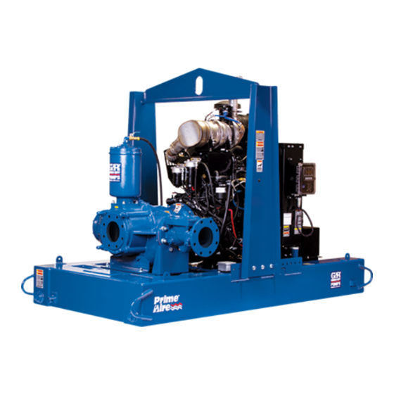
- Page 1 OM-07166-01 May 2, 2018 INSTALLATION, OPERATION, AND MAINTENANCE MANUAL WITH PARTS LIST PA SERIESr PUMP MODEL PA6A60-4045T FT4 GORMAN‐RUPP PUMPS www.grpumps.com 2015 Gorman‐Rupp Pumps Printed in U.S.A.
- Page 2 Register your new Gorman‐Rupp pump online at www.grpumps.com Valid serial number and e‐mail address required. The engine exhaust from this product contains chemicals known to the State of California to cause cancer, birth defects or other reproductive harm. RECORD YOUR PUMP MODEL AND SERIAL NUMBER Please record your pump model and serial number in the spaces provided below.
-
Page 3: Table Of Contents
TABLE OF CONTENTS INTRODUCTION ..........PAGE I - 1 SAFETY ‐... - Page 4 TABLE OF CONTENTS (continued) Engine Fuel Filter ............PAGE C - 4 Engine Oil .
-
Page 5: Introduction
PA SERIES OM-07166 INTRODUCTION Thank You for purchasing a Gorman‐Rupp pump. HAZARD AND INSTRUCTION Read this manual carefully to learn how to safely DEFINITIONS install and operate your pump. Failure to do so could result in personal injury or damage to the The following are used to alert maintenance per... -
Page 6: Safety - Section A
PA SERIES OM-07166 SAFETY ‐ SECTION A This information applies to Prime Aire the positive battery cable before per Series pumps. Refer to the manual ac forming any maintenance. Failure to do companying the engine or power so may result in serious personal injury. - Page 7 OM-07166 PA SERIES in place over the rotating parts. Ex posed rotating parts can catch clothing, fingers or tools, causing severe injury to personnel. After the pump has been installed, make certain that the pump and all piping or hose connections are tight, properly supported and secure before operation.
-
Page 8: Installation - Section B
PA SERIES OM-07166 INSTALLATION - SECTION B Review all SAFETY information in Section A. configuration, and priming must be tailored to the specific application. Since the pressure supplied Since pump installations are seldom identical, this to the pump is critical to performance and safety,... -
Page 9: Battery Installation
OM-07166 PA SERIES c. Carefully read all tags, decals, and markings POSITIONING PUMP on the pump assembly, and perform all duties indicated. Note that the pump shaft rotates in the required direction. Lifting Only operate this pump in the direction in... -
Page 10: Suction And Discharge Piping
PA SERIES OM-07166 to secure them when filled with liquid and under pressure. Gauges If the pump has been mounted on a mov able base, do not attempt to operate the The pump is drilled and tapped for installing dis... -
Page 11: Sealing
OM-07166 PA SERIES Sealing air to escape from the liquid before it is drawn into the suction inlet. Since even a slight leak will affect priming, head, If two suction lines are installed in a single sump, and capacity, especially when operating with a... -
Page 12: Discharge Lines
PA SERIES OM-07166 Figure 2. Recommended Minimum Suction Line Submergence vs. Velocity DISCHARGE LINES Siphoning If the application involves a high discharge head, gradually close the discharge Do not terminate the discharge line at a level lower than that of the liquid being pumped unless a si... -
Page 13: Float Switch Installation
OM-07166 PA SERIES Float Switch Installation pipe is available, attach the float switch cable to the standpipe in the sump at the approxi mate desired liquid level. The Float Switch autostart system employs either a single or double float switch, where a bulb raises or lowers (floats) with the liquid level, thus activating b. - Page 14 PA SERIES OM-07166 that the liquid in the priming chamber never fully Next, install a drain line between the pump drain freezes. and the wet well or sump. This line must remain submerged in the liquid below the pump down lev...
-
Page 15: Operation - Section C
OM-07166 PA SERIES OPERATION - SECTION C OPERATION Review all SAFETY information in Section A. Make sure the pump is level. Lower jack Follow the instructions on all tags, labels and stands and chock the wheels, if so decals attached to the pump. -
Page 16: Operation In Extreme Heat
OM-07166 PA SERIES and fittings tight to maintain maximum pump effi ciency. Pump Vacuum Check Never tamper with the governor to gain more power. The governor establishes Read the vacuum gauge with the pump primed safe operating limits that should not be and at operation speed. -
Page 17: Stopping
OM-07166 PA SERIES vacuum suction gauge readings regularly to detect strainer blockage. Never introduce air or steam pressure into the Never disconnect any of the safety shut pump casing or piping to remove a blockage. This down features; this will void the warran... - Page 18 OM-07166 PA SERIES Engine Fuel Filter and priming hopper to prevent damage from freez ing. Also, clean out any solids by flushing with a Consult the manual accompanying the engine, hose. Operate the pump for approximately one and change the fuel filter periodically as indicated.
- Page 19 OM-07166 PA SERIES TROUBLESHOOTING - SECTION D Review all SAFETY information in Section A. 5. Close the suction and discharge valves. 6. Vent the pump slowly and cau tiously. 7. Drain the pump. Before attempting to open or service the pump: 1.
- Page 20 OM-07166 PA SERIES TROUBLE POSSIBLE CAUSE PROBABLE REMEDY Check strainer and clean if neces Strainer clogged. PUMP STOPS OR FAILS TO DELIVER sary. RATED FLOW OR Check and clean check valve. Discharge check valve clogged. PRESSURE (cont.) Suction intake not submerged at Check installation and correct proper level or sump too small.
- Page 21 OM-07166 PA SERIES TROUBLE POSSIBLE CAUSE PROBABLE REMEDY BEARINGS RUN Bearing temperature is high, but Check bearing temperature regu TOO HOT within limits. larly to monitor any increase. Low or incorrect lubricant. Check for proper type and level of lubricant.
- Page 22 OM-07166 PA SERIES Preventive Maintenance Schedule Service Interval* Item Daily Weekly Monthly Semi‐ Annually Annually General Condition (Temperature, Unusual Noises or Vibrations, Cracks, Leaks, Loose Hardware, Etc.) Pump Performance (Gauges, Speed, Flow) Bearing Lubrication Seal Lubrication (And Packing Adjustment, If So Equipped) V‐Belts (If So Equipped)
- Page 23 OM-07166 PA SERIES PUMP MAINTENANCE AND REPAIR - SECTION E MAINTENANCE AND REPAIR OF THE WEARING PARTS OF THE PUMP WILL MAINTAIN PEAK OPERATING PERFORMANCE. STANDARD PERFORMANCE FOR PUMP MODEL PA6A60-4045T FT4 Based on 70 F (21 C) clear water at sea level Contact the Gorman‐Rupp Company to verify per...
- Page 24 OM-07166 PA SERIES PARTS PAGE ILLUSTRATION Figure 1. Pump Model PA6A60-4045T FT4 PAGE E - 2 MAINTENANCE & REPAIR...
- Page 25 OM-07166 PA SERIES Pump Model PA6A60-4045T FT4 PARTS LIST (From S/N 1729570 Up) ITEM PART PART NAME NUMBER PUMP END ASSEMBLY 46133-701 POWER UNIT KIT 46143-206 PUMP MOUNTING KIT 48157-106 BATTERY SEE OPTIONS NOT SHOWN: G‐R DECAL GR-06 PRIME AIRE DECAL...
- Page 26 OM-07166 PA SERIES ILLUSTRATION Figure 2. Power Unit Kit PAGE E - 4 MAINTENANCE & REPAIR...
- Page 27 OM-07166 PA SERIES PARTS LIST Power Unit Kit ITEM PART PART NAME NUMBER BASE/FUEL TANK ASSEMBLY 41553-053 24150 JOHN DEERE 4045T FT4 ENGINE 29224-472 CONTROL PANEL INSTALLATION KIT 48122-563 LIFTING BAIL KIT 48274-811 LOCK WASHER J10 15991 HEX NUT D10 15991...
- Page 28 OM-07166 PA SERIES ILLUSTRATION DETAIL A Figure 3. Power Unit Kit (cont'd) PAGE E - 6 MAINTENANCE & REPAIR...
- Page 29 OM-07166 PA SERIES PARTS LIST Power Unit Kit ITEM PART PART NAME NUMBER BASE/FUEL TANK ASSEMBLY 41553-053 24150 JOHN DEERE 4045T FT4 ENGINE 29224-472 CONTROL PANEL INSTALLATION KIT 48122-563 LIFTING BAIL KIT 48274-811 LOCK WASHER J10 15991 HEX NUT D10 15991...
- Page 30 OM-07166 PA SERIES ILLUSTRATION Figure 4. Pump End Assembly PAGE E - 8 MAINTENANCE & REPAIR...
- Page 31 OM-07166 PA SERIES Pump End Assembly PARTS LIST ITEM PART PART NAME NUMBER PUMP SUB ASSEMBLY 46133-906 FLANGE GASKET 1676G 18000 HOPPER SPOOL 38642-507 10000 HEX NUT D12 15991 PRIMING CHAMBER KIT 48275-005 GASKET 25113-036 CHECK VALVE ASSEMBLY 26642-134 -FLAPPER 26688-001 -O‐RING...
- Page 32 OM-07166 PA SERIES ILLUSTRATION Ï Ï Ï Ï Ì Ì Ì Ì Ì Ì Ì Ï Ï Ï Ï Ì Ì Ì Ï Ï Ì Ì Ì Ì Ì Ñ Ñ Ì Ì Ñ Ñ Ï Ì Ì Ì Ç...
- Page 33 OM-07166 PA SERIES PARTS LIST Pump Sub Assembly ITEM PART NAME PART ITEM PART NAME PART NUMBER NUMBER PUMP CASING SEE NOTE BELOW HEX HEAD CAP SCREW B0604 15991 STUD C0809 15991 LOCK WASHER J06 15991 WEAR PLATE ASSEMBLY 46451-746 24150...
- Page 34 OM-07166 PA SERIES ILLUSTRATION Figure 6. Priming Chamber Kit ITEM PART PART NAME NUMBER PRIMING CHAMBER ASSY 46112-709 PIPE BUSHING AP1608 15070 STREET ELBOW RS08 11999 BALL VALVE 26631-052 STUD C0809 15991 HEX NUT D08 15991 LOCK WASHER J08 15991...
- Page 35 OM-07166 PA SERIES ILLUSTRATION Figure 7. Priming Chamber Assembly PARTS LIST ITEM PART PART NAME NUMBER PRIMING VALVE 26664-007 -ORIFICE BUTTON 26688-021 HEX HD CAPSCREW B0806 15991 LOCKWASHER J08 15991 PRIMING VALVE GASKET 38683-657 19060 PRIMING CHAMBER 38343-020 10000 STRAINER ASSY...
- Page 36 OM-07166 PA SERIES ILLUSTRATION Figure 8. Drive Assembly PAGE E - 14 MAINTENANCE & REPAIR...
- Page 37 OM-07166 PA SERIES PARTS LIST Drive Assembly ITEM PART PART NAME NUMBER COUPLING KIT 48112-001 -BUSHING 24131-345 -COUPLING ASSEMBLY 44165-011 -LOCKWASHER J06 15991 -LOCKWASHER 21171-536 -SOCKET HD CAPSCREW BD0606-1/2 15991 -SOCKET HD CAPSCREW 22644-220 -SOCKET HD CAPSCREW BD0606-1/2S 15990 HEX HD CAPSCREW...
- Page 38 OM-07166 PA SERIES PUMP AND SEAL DISASSEMBLY any procedures not addressed in this manual are performed only after estab AND REASSEMBLY lishing that neither personal safety nor pump integrity are compromised by Review all SAFETY information in Section A. such practices.
- Page 39 OM-07166 PA SERIES ot pin. This will allow the linkage to be raised high enough to access the orifice button. Remove the hex nut and lock washer securing the Use Only Genuine Gorman-Rupp re orifice button to the linkage bar and unscrew the orifice button from the linkage bar.
- Page 40 OM-07166 PA SERIES gage the hardware (not shown) securing it to the support the sight gauge assembly while removing flywheel. the pump casing. Pull the pump casing straight away from the inter Draining Oil From Seal Cavity mediate to prevent binding on the impeller. Re...
- Page 41 OM-07166 PA SERIES suitable sized dowel to press the stationary portion Clean the bearing housing, shaft and all compo of the seal out of the seal plate from the back side. nent parts (except the bearings) with a soft cloth soaked in cleaning solvent.
- Page 42 OM-07166 PA SERIES NOTE If a hot oil bath is used to heat the bearings, both the oil and the container must be absolutely clean. If the oil has been previously used, it must be thor oughly filtered. To prevent damage during removal from the shaft, it is recommended that bearings be cleaned and inspected in place.
- Page 43 OM-07166 PA SERIES face of the oil seal should be just flush with the With the flexible portion of the coupling and the outer face of the bearing cap. bushing properly positioned on the shaft, tighten the two setscrews in an alternating sequence until Install the thrust washer (35) and bearing cap gas...
- Page 44 OM-07166 PA SERIES cannot be realigned during reassembly. Reusing an old seal could result in prema ture failure. To ease installation of the seal, lubricate the shaft A new seal assembly should be installed sleeve O‐ring and the external stationary seat O‐...
- Page 45 OM-07166 PA SERIES The I.D. of the tube should be approximately the the impeller off, and check the threads for dirt. Do same as the I.D. of the seal spring. not try to force the impeller onto the shaft. It is recommended that a tapered sleeve be installed over the shaft threads to ease installation A clearance of .025 to .040 inch (0,64 to 1,02 mm)
- Page 46 OM-07166 PA SERIES Discharge Check Valve Reassembly and ing chamber assembly on the pump suction spool Installation (3, Figure 4). Secure the priming chamber assem bly with the hardware (6 and 7). (Figure 4) Reconnect both the suction piping and the air dis...
- Page 47 For Warranty Information, Please Visit www.grpumps.com/warranty or call: U.S.: 419-755-1280 Canada: 519-631-2870 International: +1-419-755-1352 GORMAN‐RUPP PUMPS...
Need help?
Do you have a question about the PA Series and is the answer not in the manual?
Questions and answers