GORMAN-RUPP PUMPS PA Series Installation, Operation, And Maintenance Manual With Parts List
Hide thumbs
Also See for PA Series:

Related Manuals for GORMAN-RUPP PUMPS PA Series


Summary of Contents for GORMAN-RUPP PUMPS PA Series
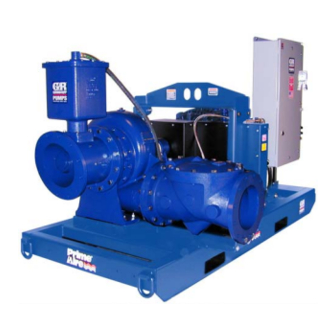
- Page 1 OM-06576-03 October 5, 2012 INSTALLATION, OPERATION, AND MAINTENANCE MANUAL WITH PARTS LIST PA SERIES PUMP MODEL PA12A60-B-E125 3P GORMAN‐RUPP PUMPS www.grpumps.com 2014 Gorman‐Rupp Pumps Printed in U.S.A.
- Page 2 Register your new Gorman‐Rupp pump online at www.grpumps.com Valid serial number and e‐mail address required. RECORD YOUR PUMP MODEL AND SERIAL NUMBER Please record your pump model and serial number in the spaces provided below. Your Gorman‐Rupp distributor needs this information when you require parts or service. Pump Model: Serial Number:...
-
Page 3: Table Of Contents
TABLE OF CONTENTS INTRODUCTION ..........PAGE I - 1 SAFETY ‐... - Page 4 TABLE OF CONTENTS (continued) Automatic Stopping ........... . PAGE C - 3 PERIODIC CHECKS .
-
Page 5: Introduction
PA SERIES OM-06576 INTRODUCTION Thank You for purchasing a Gorman‐Rupp pump. HAZARD AND INSTRUCTION Read this manual carefully to learn how to safely DEFINITIONS install and operate your pump. Failure to do so could result in personal injury or damage to the The following are used to alert maintenance per... -
Page 6: Safety - Section A
PA SERIES OM-06576 SAFETY ‐ SECTION A This information applies to Prime Air Series pumps. Refer to the manual ac companying the engine or power source before attempting to begin oper ation. The control box provides overload pro tection and power control. Do not con... - Page 7 OM-06576 PA SERIES are disengaged. Allow the pump to completely cool before servicing it. Obtain the services of a qualified elec trician to troubleshoot, test and/or ser vice the electrical components of the This pump is designed to handle most control box.
- Page 8 PA SERIES OM-06576 when required for startup or shutdown procedures. Do not operate the pump without guards in place over the rotating parts. Ex posed rotating parts can catch clothing, fingers or tools, causing severe injury to personnel. Do not remove plates, covers, gauges, pipe plugs, or fittings from an over...
-
Page 9: Installation - Section B
PA SERIES OM-06576 INSTALLATION - SECTION B Review all SAFETY information in Section A. configuration, and priming must be tailored to the specific application. Since the pressure supplied to the pump is critical to performance and safety, Since pump installations are seldom identical, this... -
Page 10: Preinstallation Inspection
OM-06576 PA SERIES PREINSTALLATION INSPECTION POSITIONING PUMP The pump assembly was inspected and tested be fore shipment from the factory. Before installation, inspect the pump for damage which may have oc curred during shipment. Check as follows: Use lifting and moving equipment in a. -
Page 11: Suction And Discharge Piping
PA SERIES OM-06576 to secure them when filled with liquid and under pressure. Gauges If the pump has been mounted on a movable base, do not attempt to operate The pump is drilled and tapped for installing dis the pump unless the unit is level. Be charge pressure and vacuum suction gauges. -
Page 12: Sealing
OM-06576 PA SERIES Sealing air to escape from the liquid before it is drawn into the suction inlet. Since even a slight leak will affect priming, head, If two suction lines are installed in a single sump, and capacity, especially when operating with a... -
Page 13: Discharge Lines
PA SERIES OM-06576 Figure 2. Recommended Minimum Suction Line Submergence vs. Velocity DISCHARGE LINES Siphoning If the application involves a high discharge head, gradually close the discharge Do not terminate the discharge line at a level lower throttling valve before stopping the pump. -
Page 14: Grounding Methods
OM-06576 PA SERIES grounding terminal to the enclosure and connect it the control box. Complete all electrical to a properly embedded electrode. connections before connecting the power supply to the control box. Make The material used for the electrode must be an ex... -
Page 15: Voltage Imbalance
PA SERIES OM-06576 available at the pump motor must be within the in the control box is properly grounded and that the dicated range. electrical data on the control matches the pump motor name plate data. Table 1. Pump Motor Voltage Limits... -
Page 16: Auto-Start
OM-06576 PA SERIES Standard floats are equipped with 50 feet (15,2 m) of cable. When installing the floats, note the following: When checking alignment, disconnect a. Be sure to provide sufficient room in the wet the power source to ensure that the well or sump so that floats do not get ob... -
Page 17: Submersible Transducer Installation
PA SERIES OM-06576 PUMP (0.9) CONTROL (.76) (Emptying) (0.6) (Filling) (.46) OPERATING (0.3) RANGE CABLE (See Table Below) TETHER (.15) POINT (Emptying) (0.3) (0.6) (0.9) (1.2) APPROXIMATE FREE CORD LENGTH IN FT. (M) 1.25” Pipe (Filling) (Not Furnished) Figure 4. Float Switch Data Submersible Transducer Installation c. - Page 18 OM-06576 PA SERIES SUCTION LINE DISCHARGE LINE SIGNAL CABLE (ATTACH TO SUCTION LINE) SUCTION STRAINER SUBMERSIBLE TRANSDUCER (DOWNSTREAM FROM SUCTION) FLOW Figure 5. Typical Submersible Transducer AutoStart Pump Installation PAGE B - 10 INSTALLATION...
- Page 19 PA SERIES OM-06576 Transducer Connections nector is required, reconnect the cable to the con nector as shown in Figure 6. The submersible transducer sensor cable is facto Once the connections are made, simply plug the ry‐equipped with a female connector which mates female connector into the male connector on the with a male connector on the back of the EPS con...
-
Page 20: Operation - Section C
OM-06576 PA SERIES OPERATION - SECTION C Review all SAFETY information in Section A. STARTING AND OPERATION Follow the instructions on all tags, labels and Control Box Function decals attached to the pump. The control box provides overload pro The electrical power used to operate tection and power control. -
Page 21: Rotation
OM-06576 PA SERIES the relay to cool after tripping before press through the field wiring connected to the control ing the reset. box. If replacing the heater pack, press the reset Rotation button to set the relay. NOTE The correct direction of pump rotation is indicated by an arrow on the pump body or accompanying If the circuit breaker trips, do not reset it immedi... -
Page 22: Priming Chamber Discharge Line
OM-06576 PA SERIES vacuum gauge reading will immediately drop pro maximum permissible operating pressure shown portionate to static suction lift, and should then sta on the pump performance curve. bilize. If the vacuum reading falls off rapidly after stabilization, an air leak exists. Before checking for STOPPING the source of the leak, check the point of installa... - Page 23 OM-06576 PA SERIES rect level (see LUBRICATION in the Maintenance Consult the manual accompanying the air com and Repair Manual). Bearing overheating can also pressor and preform all duties and checks as indi be caused by shaft misalignment and/or excessive cated.
- Page 24 OM-06576 PA SERIES TROUBLESHOOTING - SECTION D Review all SAFETY information in Section A. 5. Close the suction and discharge valves. 6. Vent the pump slowly and cau The following information is divided into two cate tiously. gories; Pump Troubleshooting and Control Box 7.
- Page 25 OM-06576 PA SERIES Pump Troubleshooting (Cont'd) TROUBLE POSSIBLE CAUSE PROBABLE REMEDY Check strainer and clean if neces Strainer clogged. PUMP STOPS OR FAILS TO DELIVER sary. RATED FLOW OR Check and clean check valve. Discharge check valve clogged. PRESSURE (cont.)
- Page 26 OM-06576 PA SERIES Pump Troubleshooting (Cont'd) TROUBLE POSSIBLE CAUSE PROBABLE REMEDY BEARINGS RUN Bearing temperature is high, but Check bearing temperature regu TOO HOT within limits. larly to monitor any increase. Low or incorrect lubricant. Check for proper type and level of lubricant.
- Page 27 OM-06576 PA SERIES PUMP PREVENTIVE MAINTENANCE equipped) between regularly scheduled inspec tions can indicate problems that can be corrected Since pump applications are seldom identical, and before system damage or catastrophic failure oc pump wear is directly affected by such things as curs.
- Page 28 OM-06576 PA SERIES PUMP MAINTENANCE AND REPAIR - SECTION E MAINTENANCE AND REPAIR OF THE WEARING PARTS OF THE PUMP WILL MAINTAIN PEAK OPERATING PERFORMANCE. STANDARD PERFORMANCE FOR PUMP MODEL PA12A60-B-E125 3P Based on 70 F (21 C) clear water at sea level Contact the Gorman‐Rupp Company to verify per...
- Page 29 OM-06576 PA SERIES PARTS PAGE ILLUSTRATION Figure 1. Pump Model PA12A60-B-E125 3P PAGE E - 2 MAINTENANCE & REPAIR...
- Page 30 OM-06576 PA SERIES Parts List Pump Model PA12A60-B-E125 3P (From S/N 1566335 Up) If your pump serial number is followed by an “N”, your pump is NOT a standard production model. Contact the Gorman‐Rupp Company to verify part numbers. ITEM...
- Page 31 OM-06576 PA SERIES ILLUSTRATION Figure 2. Pump Model PA12A60-B-E125 3P (Cont'd) PAGE E - 4 MAINTENANCE & REPAIR...
- Page 32 OM-06576 PA SERIES Parts List Pump Model PA12A60-B-E125 3P (Cont'd) (From S/N Up) If your pump serial number is followed by an “N”, your pump is NOT a standard production model. Contact the Gorman‐Rupp Company to verify part numbers. ITEM...
- Page 33 OM-06576 PA SERIES ILLUSTRATION Figure 3. Pump Model Assembly PA12A60-B PAGE E - 6 MAINTENANCE & REPAIR...
- Page 34 OM-06576 PA SERIES Parts List Pump Model Assembly PA12A60-B ITEM PART MAT'L PART NAME NUMBER CODE PUMP END ASSEMBLY 612M60-B PRIMING CHAMBER ASSEMBLY 46112-709 GASKET 4991G 18000 HEX HEAD CAP SCREW B1413 15991 NAME PLATE 38818-127 13000 DRIVE SCREW BM#04-03...
- Page 35 OM-06576 PA SERIES ILLUSTRATION SEE FIG. 5 Figure 4. 612M60-B Pump End Assembly PAGE E - 8 MAINTENANCE & REPAIR...
- Page 36 OM-06576 PA SERIES PARTS LIST 612M60-B Pump End Assembly ITEM PART NAME PART MAT'L ITEM PART NAME PART MAT'L NUMBER CODE NUMBER CODE 1 . PUMP CASING SEE NOTE BELOW ROLLER BEARING 23528-005 IMP/WEAR RING ASSY 46151-022 24110 BEARING CAP...
- Page 37 OM-06576 PA SERIES ILLUSTRATION SEE FIG. 4 Figure 5. 612M60-B Pump End Assembly (Cont'd) PAGE E - 10 MAINTENANCE & REPAIR...
- Page 38 OM-06576 PA SERIES PARTS LIST 612M60-B Pump End Assembly (Cont'd) ITEM PART NAME PART MAT'L ITEM PART NAME PART MAT'L NUMBER CODE NUMBER CODE 1 . PUMP CASING SEE NOTE BELOW ROLLER BEARING 23528-005 IMP/WEAR RING ASSY 46151-022 24110 BEARING CAP...
- Page 39 OM-06576 PA SERIES ILLUSTRATION Figure 6. 46112-709 Priming Chamber Assembly PARTS LIST ITEM PART MAT'L PART NAME NUMBER CODE PRIMING VALVE 26664-007 -ORIFICE BUTTON 26688-021 HEX HD CAPSCREW B0806 15991 LOCKWASHER 15991 PRIMING VALVE GASKET 38683-657 19060 PRIMING CHAMBER 38343-020...
- Page 40 OM-06576 PA SERIES ILLUSTRATION IMPELLER WEAR RING NOTE: UNLESS OTHERWISE SPECIFIED, MACHINED SURFACES TO BE 125 RMS. Figure 7. Impeller Assembly Machining Tolerances MAINTENANCE & REPAIR PAGE E - 13...
- Page 41 OM-06576 PA SERIES PUMP AND SEAL DISASSEMBLY any procedures not addressed in this manual are performed only after estab AND REASSEMBLY lishing that neither personal safety nor pump integrity are compromised by Review all SAFETY information in Section A. such practices.
- Page 42 OM-06576 PA SERIES Discharge Check Valve Removal and Disassembly (Figure 2) Support the discharge check valve assembly (10) Use only replacement parts provided or using a sling and a suitable lifting device. Remove approved by Gorman‐Rupp. Use of non‐ the hardware (7, 8 and 9) and separate the dis...
- Page 43 OM-06576 PA SERIES moved without separating it from the spool. How cure the assembled bottle oiler and bracket (12 and ever, if the spool gasket must be replaced, support 54, Figure 5) above the level of the oil in the seal the spool with a suitable hoist and sling, remove cavity.
- Page 44 OM-06576 PA SERIES bearing failure, or other damage to the pump. To replace the wear ring, grind off the three weld Shaft and bearing disassembly in the field spots securing the wear ring to the impeller. Use is not recommended. These operations caution not to damage the impeller.
- Page 45 OM-06576 PA SERIES flammable. Use them only in a well ven tilated area free from excessive heat, sparks, and flame. Read and follow all precautions printed on solvent contain Use caution when handling hot bearings to ers. prevent burns. Clean the bearings thoroughly in fresh cleaning NOTE solvent.
- Page 46 OM-06576 PA SERIES sleeve and a press to reposition the bearings flammable. Use them only in a well ven against the shaft shoulder. tilated area free from excessive heat, sparks, and flame. Read and follow all Secure the assembled shaft and bearings by precautions printed on solvent contain...
- Page 47 OM-06576 PA SERIES SPRING RETAINER SEAL PLATE IMPELLER SHAFT STATIONARY SLEEVE ELEMENT O‐RING IMPELLER ROTATING SHAFT ELEMENT O‐RINGS BELLOWS SHAFT SLEEVE STATIONARY SEAT IMPELLER SHIMS Figure 6. Seal Assembly Lubricate the seal sleeve O‐ring with a small amount of light oil and install it in the groove in the I.D.
- Page 48 OM-06576 PA SERIES After the impeller clearance has been set, align the machining and dynamic balancing the im pin (9) in the impeller washer (8) with the hole in the peller assembly after the wear ring is impeller and install the washer. Apply “Never‐...
- Page 49 OM-06576 PA SERIES Turn the impeller shaft by hand and check for any If the orifice button was removed, screw the new scraping or binding and correct it before putting orifice button into the linkage bar until fully seated. the pump into service.
- Page 50 OM-06576 PA SERIES Under normal conditions, drain the bearing hous ing once each year and refill with approximately 14 ounces (0,4 liter) of clean oil. Change the oil more frequently if the pump is operated continuously or Monitor the condition of the bearing lubri...
- Page 51 For U.S. and International Warranty Information, Please Visit www.grpumps.com/warranty or call: U.S.: 419-755-1280 International: +1-419-755-1352 For Canadian Warranty Information, Please Visit www.grcanada.com/warranty or call: 519-631-2870 GORMAN‐RUPP PUMPS...
Need help?
Do you have a question about the PA Series and is the answer not in the manual?
Questions and answers