Table of Contents

Subscribe to Our Youtube Channel
Related Manuals for GORMAN-RUPP PUMPS PA6D60-4045T FT4-ESP


Summary of Contents for GORMAN-RUPP PUMPS PA6D60-4045T FT4-ESP
- Page 1 OM-07081-01 December 16, 2016 Rev. A - 8/21/23 INSTALLATION, OPERATION, AND MAINTENANCE MANUAL WITH PARTS LIST PA SERIES PUMP MODEL PA6D60‐4045T FT4‐ESP GORMAN‐RUPP PUMPS www.grpumps.com 2016 Gorman‐Rupp Pumps Printed in U.S.A.
- Page 2 Register your new Gorman‐Rupp pump online at www.grpumps.com Valid serial number and e‐mail address required. The engine exhaust from this product contains chemicals known to the State of California to cause cancer, birth defects or other reproductive harm. RECORD YOUR PUMP MODEL AND SERIAL NUMBER Please record your pump model and serial number in the spaces provided below.
-
Page 3: Table Of Contents
TABLE OF CONTENTS INTRODUCTION ..........PAGE I - 1 SAFETY ‐... - Page 4 TABLE OF CONTENTS (continued) STOPPING ..............PAGE C - 3 Manual Stopping .
-
Page 5: Introduction
PA SERIES OM-07081 INTRODUCTION Thank You for purchasing a Gorman‐Rupp pump. HAZARD AND INSTRUCTION Read this manual carefully to learn how to safely DEFINITIONS install and operate your pump. Failure to do so could result in personal injury or damage to the The following are used to alert maintenance per... -
Page 6: Safety - Section A
PA SERIES OM-07081 SAFETY ‐ SECTION A This information applies to Prime Aire cable before performing any mainte Series pumps. Refer to the manual ac nance. Failure to do so may result in se companying the engine before attempt rious personal injury. ing to begin operation. - Page 7 OM-07081 PA SERIES certain that the pump and all piping or hose connections are tight, properly supported and secure before operation. Do not operate the pump without guards in place over the rotating parts. Ex posed rotating parts can catch clothing, fingers or tools, causing severe injury to personnel.
-
Page 8: Installation - Section B
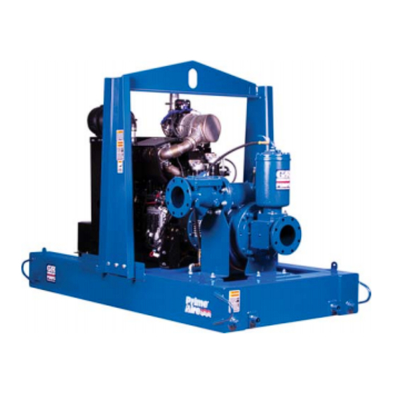
POWERED BY: JOHN DEERE 4045T FT4 DIESEL ENGINE 61.44 APPROX [ 1560,7 ] Figure 1. Pump Model PA6D60-4045T FT4-ESP PREINSTALLATION INSPECTION a. Inspect the pump for cracks, dents, damaged threads, and other obvious damage. The pump assembly was inspected and tested be... -
Page 9: Battery Installation
OM-07081 PA SERIES c. Carefully read all tags, decals, and markings good working condition and of suffi on the pump assembly, and perform all duties cient capacity and that they are posi indicated. Note that the pump shaft rotates in tioned so that loads will be balanced the required direction. -
Page 10: Suction And Discharge Piping
PA SERIES OM-07081 only; however, the engine manufacturer should be pump performance. Seal the gauge threads with consulted for continuous operation at angles pipe dope to ensure an airtight seal. Follow the greater than 15 sealant manufacturer's recommendations when selecting and applying the pipe dope. The pipe dope should be compatible with the liquid being SUCTION AND DISCHARGE PIPING pumped. -
Page 11: Suction Line In Sumps
OM-07081 PA SERIES ommendations when selecting and applying the of one or both pumps. To avoid this, position the pipe dope. The pipe dope should be compatible suction inlets so that they are separated by a dis with the liquid being pumped. tance equal to at least 3 times the diameter of the suction pipe. -
Page 12: Discharge Lines
PA SERIES OM-07081 Refer to the information which follows for installa DISCHARGE LINES tion details for the liquid level sensing system pro vided with your pump. Siphoning Float Switch Installation Do not terminate the discharge line at a level lower than that of the liquid being pumped unless a si... -
Page 13: Cold Weather Installation
OM-07081 PA SERIES ENGINE (0.9) CONTROL (.76) (Emptying) (0.6) (Filling) (.46) OPERATING (0.3) RANGE CABLE (See Table Below) TETHER (.15) POINT (Emptying) (0.3) (0.6) (0.9) (1.2) APPROXIMATE FREE CORD LENGTH IN FT. (M) 1.25” Pipe (Filling) (Not Furnished) Figure 3. Float Switch Data COLD WEATHER INSTALLATION from the line that runs between the top of the prim... -
Page 14: Operation - Section C
OM-07081 PA SERIES OPERATION - SECTION C Review all SAFETY information in Section A. cated (see LUBRICATION in MAINTENANCE AND REPAIR). Follow the instructions on all tags, labels and The pump will begin to prime upon startup. The air decals attached to the pump. in the suction line will be discharged from the educ... -
Page 15: Automatic Starting
OM-07081 PA SERIES AL'. After the engine starts and the unit is fully Adjust the engine speed to achieve the desired primed, adjust the engine RPM until the desired output. Do not exceed the factory set engine speed flow rate is achieved. and system operating pressure. -
Page 16: Operational Checks
OM-07081 PA SERIES OPERATIONAL CHECKS Allow an over‐heated pump to com pletely cool before servicing. Do not re The engine powering this unit may be move plates, covers, gauges, or fittings equipped with an EPA‐compliant Exhaust from an overheated pump. Liquid within After‐Treatment (EAT) system, which is de... - Page 17 OM-07081 PA SERIES Never disconnect any of the safety shut If the application involves a high discharge down features; this will void the warran head, gradually close the discharge ty and could result in serious damage to throttling valve before stopping the pump. the unit and/or injury to personnel.
- Page 18 OM-07081 PA SERIES Air Compressor ing. Also, clean out any solids by flushing with a hose. Operate the pump for approximately one The air compressor was lubricated for test at the minute; this will remove any remaining liquid that factory. However, always check the lubrication lev could freeze the pump rotating parts.
- Page 19 OM-07081 PA SERIES TROUBLESHOOTING - SECTION D Review all SAFETY information in Section A. Before attempting to open or service the pump: 1. Familiarize yourself with this manual. 2. Shut down the engine, disconnect the positive battery cable and take precautions to ensure that the pump will remain inoperative.
- Page 20 OM-07081 PA SERIES TROUBLE POSSIBLE CAUSE PROBABLE REMEDY Check strainer and clean if neces Strainer clogged. PUMP STOPS OR FAILS TO DELIVER sary. RATED FLOW OR Check and clean check valve. Discharge check valve clogged. PRESSURE (cont.) Suction intake not submerged at Check installation and correct proper level or sump too small.
- Page 21 OM-07081 PA SERIES TROUBLE POSSIBLE CAUSE PROBABLE REMEDY BEARINGS RUN Bearing temperature is high, but Check bearing temperature regu TOO HOT within limits. larly to monitor any increase. Low or incorrect lubricant. Check for proper type and level of lubricant. Suction and discharge lines not prop...
- Page 22 OM-07081 PA SERIES Preventive Maintenance Schedule Service Interval* Item Daily Weekly Monthly Semi‐ Annually Annually General Condition (Temperature, Unusual Noises or Vibrations, Cracks, Leaks, Loose Hardware, Etc.) Pump Performance (Gauges, Speed, Flow) Bearing Lubrication Seal Lubrication (And Packing Adjustment, If So Equipped) V‐Belts (If So Equipped) Air Release Valve Plunger Rod (If So Equipped) Front Impeller Clearance (Wear Plate)
- Page 23 OM-07081 PA SERIES PUMP MAINTENANCE AND REPAIR - SECTION E MAINTENANCE AND REPAIR OF THE WEARING PARTS OF THE PUMP WILL MAINTAIN PEAK OPERATING PERFORMANCE. STANDARD PERFORMANCE FOR PUMP MODEL PA6D60‐4045T FT4‐ESP Based on 70_F (21_C) clear water at sea level with minimum suction lift.
- Page 24 OM-07081 PA SERIES PARTS PAGE ILLUSTRATION Figure 1. Pump Model PA6D60-4045T FT4-ESP PAGE E - 2 MAINTENANCE & REPAIR...
- Page 25 OM-07081 PA SERIES Pump Model PA6D60-4045T FT4-ESP PARTS LIST (From S/N 1623785 Up) ITEM PART PART NAME NUMBER PUMP END ASSEMBLY 46183-042 J DEERE POWER UNIT 46143-191 ENCLOSURE ASSEMBLY 42164-043 TBOLT CLAMP 3.75 IN 26518-167 3.00 X 3.00 HUMP HOSE 29284-056 TBOLT CLAMP 3.5 IN...
- Page 26 OM-07081 PA SERIES ILLUSTRATION Figure 2. Pump Model PA6D60-4045T FT4-ESP PAGE E - 4 MAINTENANCE & REPAIR...
- Page 27 OM-07081 PA SERIES Pump Model PA6D60-4045T FT4-ESP PARTS LIST (Cont'd) (From S/N 1623785 Up) ITEM PART PART NAME NUMBER PUMP END ASSEMBLY 46183-042 J DEERE POWER UNIT 46143-191 ENCLOSURE ASSEMBLY 42164-043 TBOLT CLAMP 3.75 IN 26518-167 3.00 X 3.00 HUMP HOSE 29284-056 TBOLT CLAMP 3.5 IN...
- Page 28 OM-07081 PA SERIES ILLUSTRATION Figure 3. Pump Model PA6D60-4045T FT4-ESP PAGE E - 6 MAINTENANCE & REPAIR...
- Page 29 OM-07081 PA SERIES Pump Model PA6D60-4045T FT4-ESP PARTS LIST (Cont'd) (From S/N 1623785 Up) ITEM PART PART NAME NUMBER PUMP END ASSEMBLY 46183-042 J DEERE POWER UNIT 46143-191 ENCLOSURE ASSEMBLY 42164-043 TBOLT CLAMP 3.75 IN 26518-167 3.00 X 3.00 HUMP HOSE 29284-056 TBOLT CLAMP 3.5 IN...
- Page 30 OM-07081 PA SERIES ILLUSTRATION SECTION A-A Figure 4. Pump End Assembly PAGE E - 8 MAINTENANCE & REPAIR...
- Page 31 OM-07081 PA SERIES Pump End Assembly PARTS LIST ITEM PART PART NAME NUMBER PUMP SUB ASSY 46183-040 PRIMING CHAMBER KIT 48275-005 6" CHECK VALVE 26642-146 -CHECK VALVE 26642-146 -FLAPPER 26688-001 -COVER O‐RING 25152-377 -FLANGE GASKET 25113-036 HEX HEAD CAP SCREW B1212 15991 GASKET 25113-036...
- Page 32 OM-07081 PA SERIES ILLUSTRATION SECTION B-B SECTION A-A SECTION C-C VIEW D-D Figure 6. Pump Sub Assembly PAGE E - 10 MAINTENANCE & REPAIR...
- Page 33 OM-07081 PA SERIES PARTS LIST Pump Sub Assembly ITEM PART PART NAME NUMBER PUMP CASING 38218-018 10000 SUCTION SPOOL 6" 38642-625 10000 WEAR PLATE ASSEMBLY 46451-768 PIPE PLUG P16 10009 PIPE PLUG P06 15079 O‐RING 25154-381 VENTED PIPE PLUG 4823A 15079 O‐RING S1676 REPAIR ROTATING ASSEMBLY...
- Page 34 OM-07081 PA SERIES ILLUSTRATION SEAL AREA DETAIL Figure 7. Repair Rotating Assembly PAGE E - 12 MAINTENANCE & REPAIR...
- Page 35 OM-07081 PA SERIES PARTS LIST Repair Rotating Assembly ITEM PART PART NAME NUMBER IMPELLER 38628-036 11000 IMPELLER SHAFT 38515-586 1706H BALL BEARING 23422-019 BALL BEARING 23422-414 BEARING HOUSING 38251-513 10000 OIL SEAL 25227-771 SHAFT SLEEVE 31163-019 1706H O‐RING 25154-131 ADJ SHIM SET 48261-057 SEAL ASSEMBLY 46512-149...
- Page 36 OM-07081 PA SERIES ILLUSTRATION Figure 8. Priming Chamber Kit PARTS LIST ITEM PART PART NAME NUMBER PRIMING CHAMBER ASSY 46112-709 PIPE BUSHING AP1608 11999 STREET ELBOW RS08 11999 BALL VALVE 26631-052 STUD C0809 15991 HEX NUT D08 15991 LOCK WASHER J08 15991 GASKET 38687-053 19060...
- Page 37 OM-07081 PA SERIES ILLUSTRATION Figure 9. Priming Chamber Assembly PARTS LIST ITEM PART PART NAME NUMBER PRIMING VALVE 26664-007 -ORIFICE BUTTON 26688-021 HEX HD CAPSCREW B0806 15991 LOCKWASHER J08 15991 PRIMING VALVE GASKET 38683-657 19060 PRIMING CHAMBER 38343-020 10000 STRAINER ASSY 46641-222 17000 INDICATES PARTS RECOMMENDED FOR STOCK MAINTENANCE &...
- Page 38 OM-07081 PA SERIES ILLUSTRATION Figure 10. Drive Assembly PARTS LIST ITEM PART PART NAME NUMBER COUPLING ASSEMBLY 44165-016 BUSHING 24131-498 24113-603 DRIVE FLANGE 38545-004 10000 LOCKWASHER 21171-536 SOC HD CAPSCREW BD0606 1/2 15991 SOC HD CAPSCREW 22644-220 HEX HD CAPSCREW B0605 15991 HEX HD CAPSCREW 22645-164...
- Page 39 OM-07081 PA SERIES PUMP AND SEAL DISASSEMBLY the owner/maintenance personnel to ensure that only safe, established main AND REASSEMBLY tenance procedures are used, and that any procedures not addressed in this Review all SAFETY information in Section A. manual are performed only after estab Follow the instructions on all tags, label and de...
- Page 40 OM-07081 PA SERIES Priming Chamber Removal And Disassembly replacement, remove the hardware securing the cover and O‐ring. Separate the valve cover and re (Figure 8) move the flapper. Disconnect both the suction piping and the air dis Back Cover Plate and Wear Plate Removal charge tubing from the priming chamber assembly (1).
- Page 41 OM-07081 PA SERIES It is not necessary to remove the outer ring of the Turn coupling from the engine flywheel unless the cou Counterclockwise pling must be replaced. To remove the ring, disen gage the hardware (5 and 6) securing it to the fly wheel.
- Page 42 OM-07081 PA SERIES Impeller Removal Shaft and Bearing Removal and Disassembly (Figure 7) (Figure 7) When the pump is properly operated and main tained, the bearing housing should not require dis With the rotating assembly removed from the assembly. Disassemble the shaft and bearings pump casing, unscrew the impeller (1) in a coun...
- Page 43 OM-07081 PA SERIES flammable. Use them only in a well ven be cleaned and inspected in place. It is tilated area free from excessive heat, strongly recommended that the bearings sparks, and flame. Read and follow all be replaced any time the shaft and bear precautions printed on solvent contain...
- Page 44 OM-07081 PA SERIES Apply a light coating of oil to the lip of the inboard oil Align the keyway in the bushing (2) with the shaft key, and slide it onto the shaft to the dimension seal (6) and press it into the bearing housing with shown in Figure 10.
- Page 45 OM-07081 PA SERIES Install the intermediate guards (28, Figure 7), and failure. If necessary to reuse an old seal in an emer secure the drive flange (19) to the engine bellhous gency, carefully wash all metallic parts in fresh ing with the previously removed hardware (7 and cleaning solvent and allow to dry thoroughly.
- Page 46 OM-07081 PA SERIES RETAINER SEAL PLATE SPRING O‐RINGS IMPELLER SLEEVE O‐RING IMPELLER SHIMS IMPELLER SHAFT INTEGRAL SHAFT ROTATING SLEEVE ELEMENT BELLOWS SPRING CENTERING WASHER STATIONARY SEAT DRIVE BAND Figure 12. Seal Assembly as required before proceeding with seal installa tion. Lubricate the shaft sleeve (7) with a small amount This seal is not designed for operation at of light oil and slide the rotating subassembly (con...
- Page 47 OM-07081 PA SERIES Lubricate the O‐rings (13 and 14) with light grease and install them in the grooves in the wear plate and back cover. The shaft and impeller threads must be Clearance between the impeller and wear plate is adjusted using the four back cover nuts (19) and completely clean before reinstalling the im...
- Page 48 OM-07081 PA SERIES adjusting screws so the holes in the collars for the Install the cover O‐ring and secure the cover with locking screws align approximately with the holes the previously removed hardware. in the cover plate. Apply a small amount of light grease to the gasket Loosen the back cover nuts used to press the back to hold it in place and position it against the pump cover into the pump casing one full turn.
- Page 49 OM-07081 PA SERIES cation can cause the bearings to over‐heat, result LUBRICATION ing in premature bearing failure. (Figure 6) Under normal conditions, drain the bearing hous Seal Assembly ing once each year and refill with clean oil. Change the oil more frequently if the pump is operated con Fill the seal cavity through the hole for the vented tinuously or installed in an environment with rapid plug (25) with SAE No.
- Page 50 For Warranty Information, Please Visit www.grpumps.com/warranty or call: U.S.: 419-755-1280 Canada: 519-631-2870 International: +1-419-755-1352 GORMAN‐RUPP PUMPS...
Need help?
Do you have a question about the PA6D60-4045T FT4-ESP and is the answer not in the manual?
Questions and answers