GORMAN-RUPP PUMPS PA Series Installation, Operation And Maintenance Manual
Hide thumbs
Also See for PA Series:
Table of Contents
Advertisement
Quick Links
ACDEU
OM-06264-OE01
May 26, 2009
Rev. A 06‐15‐12
INSTALLATION, OPERATION,
AND MAINTENANCE MANUAL
WITH PARTS LIST
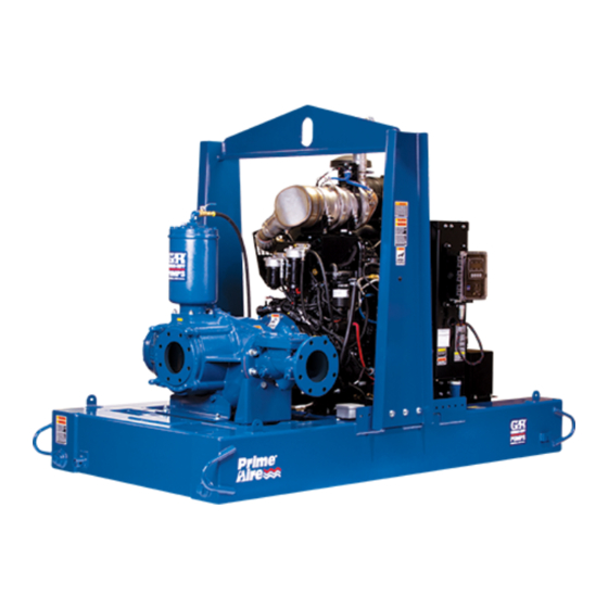
PA SERIES PUMP
MODEL
PA6G60-C9
THE GORMAN‐RUPP COMPANY D MANSFIELD, OHIO
D
GORMAN‐RUPP OF CANADA LIMITED
ST. THOMAS, ONTARIO, CANADA
Printed in U.S.A
www.grpumps.com.
E
2009 The Gorman‐Rupp Company
Advertisement
Table of Contents

Related Manuals for GORMAN-RUPP PUMPS PA Series


Summary of Contents for GORMAN-RUPP PUMPS PA Series
- Page 1 ACDEU OM-06264-OE01 May 26, 2009 Rev. A 06‐15‐12 INSTALLATION, OPERATION, AND MAINTENANCE MANUAL WITH PARTS LIST PA SERIES PUMP MODEL PA6G60-C9 THE GORMAN‐RUPP COMPANY D MANSFIELD, OHIO GORMAN‐RUPP OF CANADA LIMITED ST. THOMAS, ONTARIO, CANADA Printed in U.S.A www.grpumps.com. 2009 The Gorman‐Rupp Company...
- Page 2 Register your new Gorman‐Rupp pump online at www.grpumps.com Valid serial number and e‐mail address required. The engine exhaust from this product contains chemicals known to the State of California to cause cancer, birth defects or other reproductive harm. RECORD YOUR PUMP MODEL AND SERIAL NUMBER Please record your pump model and serial number in the spaces provided below.
-
Page 3: Table Of Contents
TABLE OF CONTENTS INTRODUCTION ..........PAGE I - 1 SAFETY ‐... - Page 4 TABLE OF CONTENTS (continued) PARTS LISTS: Pump Model ............PAGE E - 3 Power Unit Kit .
-
Page 5: Introduction
This pump is a PA Series, priming‐assisted centrif ugal model. The unit is designed for handling non‐ volatile, non‐flammable liquids containing speci fied entrained solids. The basic material of con... -
Page 7: Safety - Section A
PA SERIES OM-06264 SAFETY ‐ SECTION A This information applies to Prime Aire non‐volatile, non‐flammable liquids Series pumps. Refer to the manual ac containing specified entrained solids. companying the engine or power Do not attempt to pump volatile, corro source before attempting to begin oper... - Page 8 OM-06264 PA SERIES when required for startup or shutdown stands and chock the wheels, if so procedures. equipped. Use caution when positioning the skid‐mounted unit to prevent damage to the fuel tank. Do not remove plates, covers, gauges, pipe plugs, or fittings from an over...
-
Page 9: Installation - Section B
PA SERIES OM-06264 INSTALLATION - SECTION B Review all SAFETY information in Section A. configuration, and priming must be tailored to the specific application. Since the pressure supplied Since pump installations are seldom identical, this to the pump is critical to performance and safety,... -
Page 10: Battery Installation
OM-06264 PA SERIES c. Carefully read all tags, decals, and markings pump. If chains or cable are wrapped on the pump assembly, and perform all duties around the pump to lift it, make certain indicated. Note that the pump shaft rotates in that they are positioned so as not to the required direction. -
Page 11: Suction And Discharge Piping
PA SERIES OM-06264 possible. When operation involves a suction lift, the the leveling stands are positioned on a line must always slope upward to the pump from solid surface, and the wheels are the source of the liquid being pumped; if the line chocked. -
Page 12: Suction Line Positioning
OM-06264 PA SERIES If there is a liquid flow from an open pipe into the Suction Line Positioning sump, the flow should be kept away from the suc The depth of submergence of the suction line is tion inlet because the inflow will carry air down into critical to efficient pump operation. -
Page 13: Discharge Lines
PA SERIES OM-06264 Refer to the information which follows for installa DISCHARGE LINES tion details for the liquid level sensing system pro vided with your pump. Siphoning Float Switch Installation Do not terminate the discharge line at a level lower than that of the liquid being pumped unless a si... - Page 14 OM-06264 PA SERIES ENGINE (0.9) CONTROL (.76) (Emptying) (0.6) (Filling) (.46) OPERATING (0.3) RANGE CABLE (See Table Below) TETHER (.15) POINT (Emptying) (0.3) (0.6) (0.9) (1.2) APPROXIMATE FREE CORD LENGTH IN FT. (M) 1.25” Pipe (Filling) (Not Furnished) Figure 3. Float Switch Data...
-
Page 15: Operation - Section C
OM-06264 PA SERIES OPERATION - SECTION C Review all SAFETY information in Section A. cated (see LUBRICATION in MAINTENANCE AND REPAIR). Follow the instructions on all tags, labels and The pump will begin to prime upon startup. The air decals attached to the pump. -
Page 16: Automatic Starting
OM-06264 PA SERIES AL'. After the engine starts and the unit is fully Liquid Temperature And Overheating primed, adjust the engine RPM until the desired flow rate is achieved. The maximum liquid temperature for this pump is 160_ F (71_C). Do not apply it at a higher operating temperature. -
Page 17: Stopping
OM-06264 PA SERIES vacuum suction gauge readings regularly to detect normal for bearings, and they can operate safely to strainer blockage. at least 180_F (82_C). Checking bearing temperatures by hand is inaccu Never introduce air or steam pressure into the rate. -
Page 19: Troubleshooting - Section D
OM-06264 PA SERIES TROUBLESHOOTING - SECTION D Review all SAFETY information in Section A. Before attempting to open or service the pump: 1. Familiarize yourself with this manual. 2. Shut down the engine and discon nect the positive battery cable and take precautions to ensure that the pump will remain inoperative. - Page 20 OM-06264 PA SERIES TROUBLE POSSIBLE CAUSE PROBABLE REMEDY Check strainer and clean if neces Strainer clogged. PUMP STOPS OR FAILS TO DELIVER sary. RATED FLOW OR Check and clean check valve. Discharge check valve clogged. PRESSURE (cont.) Suction intake not submerged at Check installation and correct proper level or sump too small.
-
Page 21: Preventive Maintenance
OM-06264 PA SERIES TROUBLE POSSIBLE CAUSE PROBABLE REMEDY BEARINGS RUN Bearing temperature is high, but Check bearing temperature regu TOO HOT within limits. larly to monitor any increase. Low or incorrect lubricant. Check for proper type and level of lubricant. - Page 22 OM-06264 PA SERIES Preventive Maintenance Schedule Service Interval* Item Daily Weekly Monthly Semi‐ Annually Annually General Condition (Temperature, Unusual Noises or Vibrations, Cracks, Leaks, Loose Hardware, Etc.) Pump Performance (Gauges, Speed, Flow) Bearing Lubrication Seal Lubrication (And Packing Adjustment, If So Equipped) V‐Belts (If So Equipped)
-
Page 23: Pump Maintenance And Repair - Section E
OM-06264 PA SERIES PUMP MAINTENANCE AND REPAIR - SECTION E MAINTENANCE AND REPAIR OF THE WEARING PARTS OF THE PUMP WILL MAINTAIN PEAK OPERATING PERFORMANCE. STANDARD PERFORMANCE FOR PUMP MODEL PA6G60-C9 Based on 70 F (21 C) clear water at sea level Contact the Gorman‐Rupp Company to verify per... - Page 24 OM-06264 PA SERIES PARTS PAGE SECTION DRAWING Figure 1. Pump Model PA6G60-C9 PAGE E - 2 MAINTENANCE & REPAIR...
- Page 25 OM-06264 PA SERIES PARTS LIST Pump Model PA6G60-C9 (From S/N 1458241 Up) ITEM PART MAT'L PART NAME NUMBER CODE PUMP END ASSEMBLY 46133-759 POWER UNIT KIT 46143-072 G‐R DECAL GR-06 PUMP MOUNTING KIT 41888-079 PRIME AIRE DECAL 38812-078 NOT SHOWN:...
- Page 26 OM-06264 PA SERIES SECTION DRAWING Figure 2. 46143-072 Power Unit Kit PAGE E - 4 MAINTENANCE & REPAIR...
- Page 27 OM-06264 PA SERIES PARTS LIST 46143-072 Power Unit Kit ITEM PART MAT'L PART NAME NUMBER CODE CATERPILLAR C9 ENGINE 29236-301 LIFTING BAIL KIT 48274-806 BASE/FUEL TANK 41553-016 24150 STREET ELBOW RS08 11999 CONNECTOR 26351-065 NEG BATTERY CABLE ASSY 47311-134 POS BATTERY CABLE ASSY...
- Page 28 OM-06264 PA SERIES SECTION DRAWING Figure 3. PA6G60-(SAE 1/14) Pump End Assembly PAGE E - 6 MAINTENANCE & REPAIR...
- Page 29 OM-06264 PA SERIES PARTS LIST PA6G60-(SAE 1/14) Pump End Assembly ITEM PART MAT'L PART NAME NUMBER CODE PUMP ASSEMBLY 26837-016 SUCT SPOOL GASKET 25113-038 HEX HD CAPSCREW B1212 15991 HEX NUT 15991 PIPE PLUG 15079 8” x 6” SUCTION SPOOL...
- Page 30 OM-06264 PA SERIES SECTION DRAWING Figure 4. Pump Assembly PAGE E - 8 MAINTENANCE & REPAIR...
- Page 31 OM-06264 PA SERIES PARTS LIST Pump Assembly ITEM PART NAME PART MAT'L ITEM PART NAME PART MAT'L NUMBER CODE NUMBER CODE PUMP CASING 26835-276 LIP SEAL 26835-804 IMPELLER 26835-213 PIPE PLUG 15079 FRAME 26835-601 MECH SEAL ASSY 26835-549 BALL BEARING...
- Page 32 OM-06264 PA SERIES SECTION DRAWING Figure 5. 44162-174 Drive Assembly ITEM PART MAT'L PART NAME NUMBER CODE COUPLING KIT 48112-017 -BUSHING 24131-433 -COUPLING ASSEMBLY 24391-109 -LOCKWASHER 21171-513 -SOC HD CAPSCREW BD0812 15991 -SOC HD CAPSCREW 22644-229 HEX HD CAPSCREW B0706...
- Page 33 OM-06264 PA SERIES SECTION DRAWING Figure 6. 48275-005 Priming Chamber Kit ITEM PART MAT'L PART NAME NUMBER CODE PRIMING CHAMBER ASSY 46112-709 PIPE BUSHING AP1608 11999 STREET ELBOW RS08 11999 BALL VALVE 26631-052 STUD C0809 15991 HEX NUT 15991 LOCK WASHER...
- Page 34 OM-06264 PA SERIES SECTION DRAWING Figure 7. 46112-709 Priming Chamber Assembly ITEM PART MAT'L PART NAME NUMBER CODE PRIMING VALVE 26664-007 -ORIFICE BUTTON 26688-021 HEX HD CAPSCREW B0806 15991 LOCKWASHER 15991 PRIMING VALVE GASKET 38683-657 19060 PRIMING CHAMBER 38343-020 10000...
- Page 35 PA SERIES OM-06264 PUMP AND SEAL DISASSEMBLY 4. Check the temperature before opening any covers, plates, or AND REASSEMBLY plugs. 5. Close the suction and discharge Review all SAFETY information in Section A. valves. Follow the instructions on all tags, label and de...
- Page 36 OM-06264 PA SERIES ber. Remove the gasket (4) and clean the mating separate the spools and gasket (42) from the surfaces. pump casing (1). If the gasket (13) requires replacement, disengage If the priming valve float is stuck or the strainer (6) is the hardware (11 and 12) and separate the spools.
- Page 37 PA SERIES OM-06264 complete the cuts through the wear ring. Use cau If no further disassembly is required, refer to Seal tion not to damage the pump casing bore. Remove Installation. the wear ring sections from the pump casing. Separating Pump Frame And Drive Assembly...
- Page 38 OM-06264 PA SERIES No provisions are made for draining the lubricant precautions printed on solvent contain for disassembly. Position a drip pan under the ers. frame before proceeding with shaft and bearing re Clean the bearings thoroughly in fresh cleaning moval.
- Page 39 PA SERIES OM-06264 oil and the container must be absolutely clean. If full (up to the bottom of the shaft) before reinstal the oil has been previously used, it must be thor ling the shaft and bearings. oughly filtered. Secure the bearings (29) on the shaft with the bear...
- Page 40 OM-06264 PA SERIES Drive Assembly Installation tion of the coupling with a non‐petroleum based lubricant such as vegetable oil or glycerin, or a sili (Figure 5) con‐based lubricant such as “WD40” or equivalent. Do not use petroleum‐based lubricants, or any oth...
- Page 41 PA SERIES OM-06264 ROTATING O‐RING RETAINER ELEMENT SPRING IMPELLER STATIONARY SEAT SHAFT SLEEVE IMPELLER SHAFT SPRING HOLDER V‐RING LIP SEAL & BELLOWS SPRING Figure 8. Seal Assembly Lubricate the shaft sleeve with light oil and slide it onto the impeller shaft until it seats against the shaft shoulder.
- Page 42 OM-06264 PA SERIES plate until it seats squarely against the bore shoul Pipe der. Long Capscrew Carefully slide the assembled back plate, lip seal and stationary seal seat over the shaft sleeve until the back plate seats against the bracket (39). Se...
- Page 43 PA SERIES OM-06264 opening or cleanout cover opening as described in Suction Spool Installation Pump Casing And Wear Ring Removal. With the (Figure 4) impeller immobilized, torque the impeller lock screw to the specifications shown in Table E-1. If the gasket (13) was removed, install a new gas...
- Page 44 OM-06264 PA SERIES threads on the orifice button. When adjustment is Bearings complete, install and tighten the lock washer and hex nut securing the orifice button. (Figure 4) Install the strainer (6) and priming valve gasket (4). The bearings were fully lubricated when shipped Lower the float into the priming chamber (5) and from the factory.
- Page 45 For U.S. and International Warranty Information, Please Visit www.grpumps.com/warranty or call: U.S.: 419-755-1280 International: +1-419-755-1352 For Canadian Warranty Information, Please Visit www.grcanada.com/warranty or call: 519-631-2870 THE GORMAN‐RUPP COMPANY D MANSFIELD, OHIO GORMAN‐RUPP OF CANADA LIMITED ST. THOMAS, ONTARIO, CANADA...
Need help?
Do you have a question about the PA Series and is the answer not in the manual?
Questions and answers