GORMAN-RUPP PUMPS PA Series Installation, Operation And Maintenance Manual
Hide thumbs
Also See for PA Series:
Table of Contents
Advertisement
Quick Links
ACDEU
OM−06057−01
October 9, 2007
INSTALLATION, OPERATION,
AND MAINTENANCE MANUAL
WITH PARTS LIST
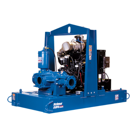
PA SERIES PUMP
MODEL
PA12A60−B−6068T−ESP
THE GORMAN-RUPP COMPANY D MANSFIELD, OHIO
D
GORMAN-RUPP OF CANADA LIMITED
ST. THOMAS, ONTARIO, CANADA
Printed in U.S.A
www.grpumps.com.
E
Copyright by the Gorman-Rupp Company
Advertisement
Table of Contents

Related Manuals for GORMAN-RUPP PUMPS PA Series


Summary of Contents for GORMAN-RUPP PUMPS PA Series
- Page 1 ACDEU OM−06057−01 October 9, 2007 INSTALLATION, OPERATION, AND MAINTENANCE MANUAL WITH PARTS LIST PA SERIES PUMP MODEL PA12A60−B−6068T−ESP THE GORMAN-RUPP COMPANY D MANSFIELD, OHIO GORMAN-RUPP OF CANADA LIMITED ST. THOMAS, ONTARIO, CANADA Printed in U.S.A www.grpumps.com. Copyright by the Gorman-Rupp Company...
- Page 2 Register your new Gorman-Rupp pump online at www.grpumps.com Valid serial number and e-mail address required. The engine exhaust from this product contains chemicals known to the State of California to cause cancer, birth defects or other reproductive harm. RECORD YOUR PUMP MODEL AND SERIAL NUMBER Please record your pump model and serial number in the spaces provided below.
-
Page 3: Table Of Contents
TABLE OF CONTENTS INTRODUCTION ..........PAGE I −... - Page 4 TABLE OF CONTENTS (continued) PARTS LIST: Pump Model ............PAGE E −...
-
Page 5: Introduction
Gor- man-Rupp pump. This pump is a sound-attenuated PA Series, pri- ming-assisted environmental silent pump. The centrifugal pump unit is designed for handling Immediate hazards which WILL result in non-volatile, non-flammable liquids containing severe personal injury or death. -
Page 6: Safety - Section A
PA SERIES OM−06057 SAFETY - SECTION A This information applies to Prime Aire the positive battery cable before per- forming any maintenance. Failure to do Series pumps. Refer to the manual ac- so may result in serious personal injury. companying the engine or power source before attempting to begin oper- ation. - Page 7 OM−06057 PA SERIES liquid could come to a boil, build pres- stands and chock the wheels, if so sure, and cause the pump casing to rup- equipped. Use caution when positioning ture or explode. Momentary closure of a the skid-mounted unit to prevent damage discharge valve is acceptable only to the fuel tank.
-
Page 8: Installation − Section Bpage B
PA SERIES OM−06057 INSTALLATION − SECTION B Review all SAFETY information in Section A. configuration, and priming must be tailored to the specific application. Since the pressure supplied Since pump installations are seldom identical, this to the pump is critical to performance and safety,... -
Page 9: Battery Installation
OM−06057 PA SERIES c. Carefully read all tags, decals, and markings POSITIONING PUMP on the pump assembly, and perform all duties indicated. Note that the pump shaft rotates in the required direction. Use lifting and moving equipment in good repair and with adequate capacity to prevent injuries to personnel or dam- age to equipment. -
Page 10: Suction And Discharge Piping
PA SERIES OM−06057 the brake and blocking the wheels before attempt- lines are used, they should have adequate support ing to operate the pump. to secure them when filled with liquid and under pressure. Gauges The pump is drilled and tapped for installing dis- If the pump has been mounted on a mov- charge pressure and vacuum suction gauges. -
Page 11: Sealing
OM−06057 PA SERIES Sealing air to escape from the liquid before it is drawn into the suction inlet. Since even a slight leak will affect priming, head, If two suction lines are installed in a single sump, and capacity, especially when operating with a... -
Page 12: Discharge Lines
PA SERIES OM−06057 Figure 2. Recommended Minimum Suction Line Submergence vs. Velocity DISCHARGE LINES Siphoning If the application involves a high discharge head, gradually close the discharge Do not terminate the discharge line at a level lower than that of the liquid being pumped unless a si- throttling valve before stopping the pump. -
Page 13: Float Switch Installation
OM−06057 PA SERIES Float Switch Installation pipe is available, attach the float switch cable to the standpipe in the sump at the approxi- The Float Switch autostart system employs either a mate desired liquid level. single or double float switch, where a bulb raises or lowers (floats) with the liquid level, thus activating b. -
Page 14: Operation − Section C
OM−06057 PA SERIES OPERATION − SECTION C Review all SAFETY information in Section A. The pump will begin to prime upon startup. The air in the suction line will be discharged from the educ- Follow the instructions on all tags, labels and tor discharge line. -
Page 15: Automatic Starting
OM−06057 PA SERIES Automatic Starting With the float system installed, follow the proce- dures outlined for manual starting and throttle ad- Allow an over-heated pump to com- justment. Switch the keyswitch to ‘OFF’ until the pletely cool before servicing. Do not re-... -
Page 16: Bearing Temperature Check
OM−06057 PA SERIES shock waves can be transmitted to the pump and A sudden increase in bearing temperatures is a piping system. Close all connecting valves slowly. warning that the bearings are at the point of failing to operate properly. Make certain that the bearing... -
Page 17: Troubleshooting − Section D
OM−06057 PA SERIES TROUBLESHOOTING − SECTION D Review all SAFETY information in Section A. Before attempting to open or service the pump: 1. Familiarize yourself with this manual. 2. Shut down the engine and discon- nect the positive battery cable to en- sure that the pump will remain inop- erative. - Page 18 OM−06057 PA SERIES TROUBLE POSSIBLE CAUSE PROBABLE REMEDY Check strainer and clean if neces- Strainer clogged. PUMP STOPS OR FAILS TO DELIVER sary. RATED FLOW OR Check and clean check valve. Discharge check valve clogged. PRESSURE (cont.) Suction intake not submerged at Check installation and correct proper level or sump too small.
-
Page 19: Preventive Maintenance
OM−06057 PA SERIES TROUBLE POSSIBLE CAUSE PROBABLE REMEDY BEARINGS RUN Bearing temperature is high, but Check bearing temperature regu- TOO HOT within limits. larly to monitor any increase. Low or incorrect lubricant. Check for proper type and level of lubricant. - Page 20 OM−06057 PA SERIES Preventive Maintenance Schedule Service Interval* Item Daily Weekly Monthly Semi- Annually Annually General Condition (Temperature, Unusual Noises or Vibrations, Cracks, Leaks, Loose Hardware, Etc.) Pump Performance (Gauges, Speed, Flow) Bearing Lubrication Seal Lubrication (And Packing Adjustment, If So Equipped)
-
Page 21: Pump Maintenance And Repair - Section E
OM−06057 PA SERIES PUMP MAINTENANCE AND REPAIR − SECTION E MAINTENANCE AND REPAIR OF THE WEARING PARTS OF THE PUMP WILL MAINTAIN PEAK OPERATING PERFORMANCE. STANDARD PERFORMANCE FOR PUMP MODEL PA12A60−B−6068T−ESP Based on 70_F (21_C) clear water at sea level Contact the Gorman-Rupp Company to verify per- formance or part numbers. - Page 22 OM−06057 PA SERIES PARTS PAGE SECTION DRAWING Figure 1. Pump Model PA12A60−B−6068T−ESP PAGE E − 2 MAINTENANCE & REPAIR...
- Page 23 OM−06057 PA SERIES PARTS LIST Pump Model PA12A60−B−6068T−ESP (From S/N 1378838 Up) If your pump serial number is followed by an N", your pump is NOT a standard production model. Contact the Gorman-Rupp Company to verify part numbers. ITEM PART NAME PART MAT’L...
- Page 24 OM−06057 PA SERIES SECTION DRAWING Figure 2. Pump Model PA12A60−B−6068T−ESP (Cont’d) PAGE E − 4 MAINTENANCE & REPAIR...
- Page 25 OM−06057 PA SERIES PARTS LIST Pump Model PA12A60−B−6068T−ESP (Cont’d) (From S/N 1378838 Up) ITEM PART MAT’L PART NAME NUMBER CODE INTAKE TUBE ASSY 46671−501 24150 HOSE BARB FITTING 26523−392 −−− .75" ID X 52" LG HOSE 18513−305 −−− AIR INTAKE ELBOW...
- Page 26 OM−06057 PA SERIES SECTION DRAWING Figure 3. Pump Model PA12A60−B−6068T−ESP (Cont’d) PAGE E − 6 MAINTENANCE & REPAIR...
- Page 27 OM−06057 PA SERIES PARTS LIST Pump Model PA12A60−B−6068T−ESP (Cont’d) (From S/N 1378838 Up) ITEM PART MAT’L PART NAME NUMBER CODE RED PIPE BUSHING AP0604 14100 CONNECTOR 26351−059 −−− .38" ID X 56" LG HOSE 18513−302 −−− .19" ID X 40" LG HOSE 18513−301...
- Page 28 OM−06057 PA SERIES SECTION DRAWING Figure 4. 46133−726 Pump Model Assembly PAGE E − 8 MAINTENANCE & REPAIR...
- Page 29 OM−06057 PA SERIES PARTS LIST 46133−726 Pump Model Assembly ITEM PART MAT’L PART NAME NUMBER CODE PUMP ASSMEBLY 612M60−B −−− HEX HD CAPSCREW B1415 15991 LOCKWASHER 15991 HEX NUT 15991 12" CHECK VALVE 26642−128 −−− −FLAPPER 26688−003 −−− −COVER GASKET 26688−004...
- Page 30 OM−06057 PA SERIES SECTION DRAWING SEE FIG. 6 Figure 5. 612M60−B Pump Model Assembly PAGE E − 10 MAINTENANCE & REPAIR...
- Page 31 OM−06057 PA SERIES PARTS LIST 612M60−B Pump Model Assembly ITEM PART NAME PART MAT’L ITEM PART NAME PART MAT’L NUMBER CODE NUMBER CODE PUMP CASING 38219−305 10010 ROLLER BEARING 23528−005 −−− IMP/WEAR RING ASSY 46151−022 24110 BEARING CAP 38322−425 10010 −IMPELLER...
- Page 32 OM−06057 PA SERIES SECTION DRAWING SEE FIG. 5 Figure 6. 612M60−B Pump Model Assembly (Cont’d) PAGE E − 12 MAINTENANCE & REPAIR...
- Page 33 OM−06057 PA SERIES PARTS LIST 612M60−B Pump Model Assembly (Cont’d) ITEM PART NAME PART MAT’L ITEM PART NAME PART MAT’L NUMBER CODE NUMBER CODE PUMP CASING 38219−305 10010 ROLLER BEARING 23528−005 −−− IMP/WEAR RING ASSY 46151−022 24110 BEARING CAP 38322−425 10010 −IMPELLER...
- Page 34 OM−06057 PA SERIES SECTION DRAWING Figure 7. 48275−006 Priming Chamber Kit ITEM PART MAT’L PART NAME NUMBER CODE BALL VALVE 26631−054 −−− STREET ELBOW RS16 11999 PRIMING CHAMBER ASSEMBLY 36112−709 −−− HEX NUT 15991 LOCK WASHER 15991 STUD C0809 15991 BAFFLE 31113−011...
- Page 35 OM−06057 PA SERIES SECTION DRAWING Figure 8. 46112−709 Priming Chamber Assembly ITEM PART MAT’L PART NAME NUMBER CODE PRIMING VALVE 26664−007 −−− −ORIFICE BUTTON 26688−021 −−− HEX HD CAPSCREW B0806 15991 LOCKWASHER 15991 PRIMING VALVE GASKET 38683−657 19060 PRIMING CHAMBER 38343−020...
- Page 36 OM−06057 PA SERIES SECTION DRAWING Figure 9. 44162−179 Engine Drive Assembly ITEM PART MAT’L PART NAME NUMBER CODE RETAINING RING 24121−075 −−− RETAINING RING S215 −−− BALL BEARING 23282−012 −−− OUTPUT SHAFT 38512−051 1706H N0612 15990 BEARING HOUSING 38251−001 11010 SOCKET HEAD CAPSCREW BD0606−1/2...
- Page 37 OM−06057 PA SERIES SECTION DRAWING IMPELLER WEAR RING NOTE: UNLESS OTHERWISE SPECIFIED, MACHINED SURFACES TO BE 125 RMS. Figure 10. Impeller Assembly Machining Tolerances MAINTENANCE & REPAIR PAGE E − 17...
- Page 38 OM−06057 PA SERIES PUMP AND SEAL DISASSEMBLY 4. Check the temperature before opening any covers, plates, or AND REASSEMBLY plugs. 5. Close the suction and discharge Review all SAFETY information in Section A. valves. Follow the instructions on all tags, label and de- 6.
- Page 39 PA SERIES OM−06057 pass through the priming chamber after adjusting three holes horizontally, 180_ apart, through the the orifice button (see Priming Chamber Reas- wear ring between each of the spiral pins. Use a sembly and Installation for adjustment), the but- chisel or other suitable tool to complete the cuts ton may require replacement.
- Page 40 OM−06057 PA SERIES the casing gasket (6) and clean the contacting sur- uid being pumped leaks past the oil seal, both faces. seals should be replaced immediately. Remove the impeller shims (42). Tie and tag the Impeller Removal shims for ease of reassembly. Remove the seal spring.
- Page 41 PA SERIES OM−06057 Pump Shaft Bearing Removal Place a block of wood against the impeller end of Disassembly the shaft (32) and tap the shaft and assembled bearings (30 and 34) out of the pedestal. (Figure 2) After removing the shaft and bearings, clean and...
- Page 42 OM−06057 PA SERIES Most cleaning solvents are toxic and Shaft and bearing disassembly in the field flammable. Use them only in a well ven- is not recommended. These operations tilated area free from excessive heat, should be performed only in a properly sparks, and flame.
- Page 43 PA SERIES OM−06057 The bearings may be heated to ease installation. Install the key (5) in the output shaft keyway. Posi- An induction heater, hot oil bath, electric oven, or tion the flexible portion of the coupling assembly hot plate may be used to heat the bearings. Bear- (3) on the shaft as shown in Figure 9.
- Page 44 OM−06057 PA SERIES 242’ or equivalent compound to the threads of the hardware (7and 9), and secure the outer ring of the coupling to the engine flywheel by torquing the hardware to 45 ft. lbs. (540 in. lbs. or 6,2 m. kg.).
- Page 45 PA SERIES OM−06057 Secure the assembled shaft and bearings by Position the hub and sprocket to the dimensions clamping on the surface between the bearings. shown in Figure 11 and torque the mounting caps- Use caution not to scratch or mar the part number crews to 75 ft.
- Page 46 OM−06057 PA SERIES Install a new O-ring (37) in the groove in the seal plate and secure the seal plate cover to the seal plate with the hardware (46 and 47). The inner edge of the pump pulley must be...
- Page 47 PA SERIES OM−06057 SPRING RETAINER SEAL PLATE IMPELLER SHAFT STATIONARY SLEEVE ELEMENT O-RING IMPELLER ROTATING SHAFT ELEMENT O-RINGS BELLOWS SHAFT SLEEVE STATIONARY SEAT IMPELLER SHIMS Figure 12. Seal Assembly the pedestal with three 1/2-inch by 2-inch long capscrews and nuts (not supplied).
- Page 48 OM−06057 PA SERIES Impeller Installation A clearance of approximately .015 inch (0,38 mm) between the impeller and the seal plate is recom- (Figure 5) mended for maximum pump efficiency. Measure this clearance, and add or remove impeller adjust- ing shims as required.
- Page 49 PA SERIES OM−06057 Install the suction head gasket (52). Position the threads on the orifice button. When adjustment is suction head over the studs (53) and secure it with complete, install and tighten the lock washer and the hardware (14 and 15).
- Page 50 OM−06057 PA SERIES For cold weather operation, consult the factory or a lubricant supplier for the recommended grade of oil. Monitor the condition of the bearing lubri- cant regularly for evidence of rust or mois- Engine ture condensation. This is especially im-...
- Page 51 For U.S. and International Warranty Information, Please Visit www.grpumps.com/warranty or call: U.S.: 419−755−1280 International: +1−419−755−1352 For Canadian Warranty Information, Please Visit www.grcanada.com/warranty or call: 519−631−2870 THE GORMAN-RUPP COMPANY D MANSFIELD, OHIO GORMAN-RUPP OF CANADA LIMITED ST. THOMAS, ONTARIO, CANADA...
Need help?
Do you have a question about the PA Series and is the answer not in the manual?
Questions and answers