GORMAN-RUPP PUMPS PA Series Installation, Operation, And Maintenance Manual With Parts List
Hide thumbs
Also See for PA Series:
Table of Contents
Advertisement
Quick Links
ACDEU
OM-05853-02
January 18, 2006
INSTALLATION, OPERATION,
AND MAINTENANCE MANUAL
WITH PARTS LIST
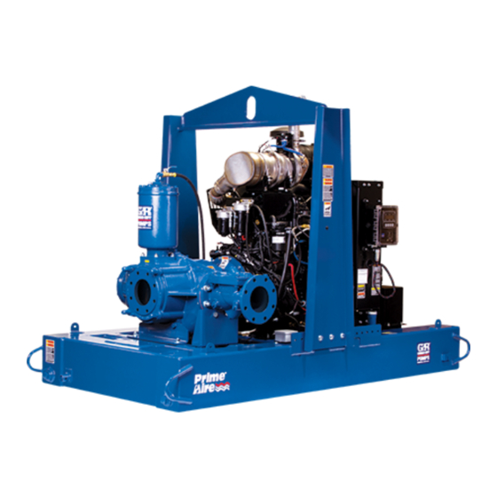
PA SERIES PUMP
MODEL
PA6C60-B-E50 460/3
PA6C60−B−(E50)
66F60−B−(E50)
THE GORMAN-RUPP COMPANY D MANSFIELD, OHIO
D
GORMAN-RUPP OF CANADA LIMITED
ST. THOMAS, ONTARIO, CANADA
Printed in U.S.A
www.gormanrupp.com.
E
Copyright by the Gorman-Rupp Company
Advertisement
Table of Contents

Subscribe to Our Youtube Channel
Related Manuals for GORMAN-RUPP PUMPS PA Series


Summary of Contents for GORMAN-RUPP PUMPS PA Series
- Page 1 ACDEU OM-05853-02 January 18, 2006 INSTALLATION, OPERATION, AND MAINTENANCE MANUAL WITH PARTS LIST PA SERIES PUMP MODEL PA6C60-B-E50 460/3 PA6C60−B−(E50) 66F60−B−(E50) THE GORMAN-RUPP COMPANY D MANSFIELD, OHIO GORMAN-RUPP OF CANADA LIMITED ST. THOMAS, ONTARIO, CANADA Printed in U.S.A www.gormanrupp.com. Copyright by the Gorman-Rupp Company...
-
Page 2: Table Of Contents
TABLE OF CONTENTS INTRODUCTION ..........PAGE I −... - Page 3 TABLE OF CONTENTS (continued) Automatic Stopping ........... . PAGE C −...
-
Page 4: Introduction
This pump is a PA Series, priming-assisted centrif- ugal model. The unit is designed for handling non- volatile, non-flammable liquids containing speci- fied entrained solids. The basic material of con- struction is ductile iron, with stainless steel shaft and ductile iron wearing parts. -
Page 5: Safety - Section A
PA SERIES OM−05853 SAFETY - SECTION A This information applies to Prime Air Series pumps. Refer to the manual ac- companying the engine or power source before attempting to begin oper- ation. The control box provides overload pro- tection and power control. Do not con-... - Page 6 OM−05853 PA SERIES are disengaged. Allow the pump to completely cool before servicing it. Obtain the services of a qualified elec- trician to troubleshoot, test and/or ser- vice the electrical components of the This pump is designed to handle most control box.
- Page 7 PA SERIES OM−05853 when required for startup or shutdown procedures. Do not operate the pump without guards in place over the rotating parts. Ex- posed rotating parts can catch clothing, Do not remove plates, covers, gauges, fingers or tools, causing severe injury to pipe plugs, or fittings from an over- personnel.
-
Page 8: Installation − Section Bpage B
PA SERIES OM−05853 INSTALLATION − SECTION B Review all SAFETY information in Section A. configuration, and priming must be tailored to the specific application. Since the pressure supplied to the pump is critical to performance and safety, Since pump installations are seldom identical, this... -
Page 9: Preinstallation Inspection
OM−05853 PA SERIES PREINSTALLATION INSPECTION POSITIONING PUMP The pump assembly was inspected and tested be- fore shipment from the factory. Before installation, inspect the pump for damage which may have oc- curred during shipment. Check as follows: Use lifting and moving equipment in a. -
Page 10: Suction And Discharge Piping
PA SERIES OM−05853 to secure them when filled with liquid and under pressure. Gauges If the pump has been mounted on a movable base, do not attempt to operate The pump is drilled and tapped for installing dis- the pump unless the unit is level. Be charge pressure and vacuum suction gauges. -
Page 11: Sealing
OM−05853 PA SERIES Sealing air to escape from the liquid before it is drawn into the suction inlet. Since even a slight leak will affect priming, head, If two suction lines are installed in a single sump, and capacity, especially when operating with a... -
Page 12: Discharge Lines
PA SERIES OM−05853 Figure 2. Recommended Minimum Suction Line Submergence vs. Velocity DISCHARGE LINES Siphoning If the application involves a high discharge head, gradually close the discharge Do not terminate the discharge line at a level lower throttling valve before stopping the pump. -
Page 13: Field Wiring Connections (Incoming Power)
OM−05853 PA SERIES grounding terminal to the enclosure and connect it the control box. Complete all electrical to a properly embedded electrode. connections before connecting the power supply to the control box. Make The material used for the electrode must be an ex- certain to ground the appropriate lead cellent conductor of electricity, such as copper. -
Page 14: Voltage Imbalance
PA SERIES OM−05853 available at the pump motor must be within the in- electrical data on the control matches the pump dicated range. motor name plate data. Table 1. Pump Motor Voltage Limits Connect the power cable to the control box as... -
Page 15: Auto-Start
OM−05853 PA SERIES Standard floats are equipped with 50 feet (15,2 m) of cable. When installing the floats, note the following: When checking alignment, disconnect a. Be sure to provide sufficient room in the wet the power source to ensure that the well or sump so that floats do not get ob- pump will remain inoperative. -
Page 16: Submersible Transducer Installation
PA SERIES OM−05853 PUMP (0.9) CONTROL (.76) (Emptying) (0.6) (Filling) (.46) OPERATING (0.3) RANGE CABLE (See Table Below) TETHER (.15) POINT (Emptying) (0.3) (0.6) (0.9) (1.2) APPROXIMATE FREE CORD LENGTH IN FT. (M) 1.25" Pipe (Filling) (Not Furnished) Figure 4. Float Switch Data Submersible Transducer Installation c. - Page 17 OM−05853 PA SERIES SUCTION LINE DISCHARGE LINE SIGNAL CABLE (ATTACH TO SUCTION LINE) SUCTION STRAINER SUBMERSIBLE TRANSDUCER (DOWNSTREAM FROM SUCTION) FLOW Figure 5. Typical Submersible Transducer AutoStart Pump Installation PAGE B − 10 INSTALLATION...
- Page 18 PA SERIES OM−05853 Transducer Connections nector is required, reconnect the cable to the con- nector as shown in Figure 6. The submersible transducer sensor cable is facto- Once the connections are made, simply plug the ry-equipped with a female connector which mates...
-
Page 19: Operation − Section C
OM−05853 PA SERIES OPERATION − SECTION C Review all SAFETY information in Section A. STARTING AND OPERATION Follow the instructions on all tags, labels and Control Box Function decals attached to the pump. The control box provides overload pro- The electrical power used to operate tection and power control. -
Page 20: Rotation
OM−05853 PA SERIES the relay to cool after tripping before press- the pump, but does not terminate incoming power ing the reset. through the field wiring connected to the control box. If replacing the heater pack, press the reset button to set the relay. -
Page 21: Pump Vacuum Check
OM−05853 PA SERIES Pump Vacuum Check Never introduce air or steam pressure into the pump casing or piping to remove a blockage. This could result in personal injury or damage to the Read the vacuum gauge with the pump primed equipment. - Page 22 OM−05853 PA SERIES A sudden increase in bearing temperatures is a ensure proper tension. Refer to the separate docu- warning that the bearings are at the point of failing ment accompanying the unit for V-belt replace- to operate properly. Make certain that the bearing ment and adjustment procedures.
- Page 23 OM−05853 PA SERIES TROUBLESHOOTING − SECTION D Review all SAFETY information in Section A. 5. Close the suction and discharge valves. 6. Vent the pump slowly and cau- The following information is divided into two cate- tiously. gories; Pump Troubleshooting and Control Box 7.
- Page 24 OM−05853 PA SERIES Pump Troubleshooting (Cont’d) TROUBLE POSSIBLE CAUSE PROBABLE REMEDY Check strainer and clean if neces- Strainer clogged. PUMP STOPS OR FAILS TO DELIVER sary. RATED FLOW OR Check and clean check valve. Discharge check valve clogged. PRESSURE (cont.)
- Page 25 OM−05853 PA SERIES Pump Troubleshooting (Cont’d) TROUBLE POSSIBLE CAUSE PROBABLE REMEDY BEARINGS RUN Bearing temperature is high, but Check bearing temperature regu- TOO HOT within limits. larly to monitor any increase. Low or incorrect lubricant. Check for proper type and level of lubricant.
- Page 26 OM−05853 PA SERIES PUMP PREVENTIVE MAINTENANCE equipped) between regularly scheduled inspec- tions can indicate problems that can be corrected Since pump applications are seldom identical, and before system damage or catastrophic failure oc- pump wear is directly affected by such things as curs.
- Page 27 OM−05768 PA SERIES PUMP MAINTENANCE AND REPAIR − SECTION E MAINTENANCE AND REPAIR OF THE WEARING PARTS OF THE PUMP WILL MAINTAIN PEAK OPERATING PERFORMANCE. STANDARD PERFORMANCE FOR PUMP MODEL PA6C60-B-E50 460/3 Based on 70_F (21_C) clear water at sea level Contact the Gorman-Rupp Company to verify per- formance or part numbers.
- Page 28 OM−05768 PA SERIES PARTS PAGE SECTION DRAWING Figure 1. Pump Model PA6C60-B-E50 460/3 PAGE E − 2 MAINTENANCE & REPAIR...
- Page 29 OM−05768 PA SERIES Pump Model PA6C60−B−E50 460/3 (From S/N 1328620 up) If your pump serial number is followed by an N", your pump is NOT a standard production model. Contact the Gorman-Rupp Company to verify part numbers. ITEM PART NAME PART MAT’L...
- Page 30 OM−05768 PA SERIES SECTION DRAWING Figure 2. Pump Model PA6C60−B−E50 460/3 ITEM PART NAME PART MAT’L ITEM PART NAME PART MAT’L NUMBER CODE NUMBER CODE MALE ADAPTOR 26351−065 −−− NOT SHOWN: SHIM SET 48261−045 −−− 460 VOLT TAG 38816−460 −−−...
- Page 31 OM−05768 PA SERIES Figure 3. Pump End Assembly PA6C60−B−(E50) ITEM PART MAT’L PART NAME NUMBER CODE PUMP END ASSY 66F60−B−(E50) −−− CHECK VALVE KIT 48274−015 −−− −6" CHECK VALVE 26642−126 −−− −−FLAPPER 26688−001 −−− −−COVER O-RING 25152−377 −−− −FLANGE GASKET 25113−036...
- Page 32 OM−05768 PA SERIES SECTION DRAWING Figure 4. 66F60−B−(E50) Pump End Assembly PAGE E − 6 MAINTENANCE & REPAIR...
- Page 33 S1676 −−− HEX HD CAPSCREW B0804−1/2 15991 LOCKWASHER 15991 NOT SHOWN: PIPE PLUG 15079 OIL LEVEL DECAL 38816−123 −−− PA SERIES NAME PLATE 38818−127 13000 DRIVE SCREW BM#04−03 17000 60 SERIES NAME PLATE 2613R 13990 DRIVE SCREW BM#04−03 17000 OPTIONAL: THREADED FLANGE KIT 48274−205...
- Page 34 OM−05768 PA SERIES SECTION DRAWING DRIVE END VIEW Figure 5. 44163−445 Repair Rotating Assembly PAGE E − 8 MAINTENANCE & REPAIR...
- Page 35 OM−05768 PA SERIES PARTS LIST 44163−443 Repair Rotating Assembly ITEM PART MAT’L PART NAME NUMBER CODE IMPELLER 38615−097 11010 SEAL ASSY 46512−149 −−− INBOARD BALL BEARING 23422−019 −−− BEARING HOUSING 38251−513 10000 VENTED PLUG 4823A 15079 AIR VENT S1530 −−−...
- Page 36 OM−05768 PA SERIES SECTION DRAWING Figure 6. 48275−005 Priming Chamber Kit ITEM PART MAT’L PART NAME NUMBER CODE PRIMING CHAMBER ASSY 46112−709 −−− PIPE BUSHING AP1608 11999 STREET ELBOW RS08 11999 BALL VALVE 26631−052 −−− STUD C0809 15991 HEX NUT...
- Page 37 OM−05768 PA SERIES SECTION DRAWING Figure 7. 46112−709 Priming Chamber Assembly PARTS LIST ITEM PART MAT’L PART NAME NUMBER CODE PRIMING VALVE 26664−007 −−− −ORIFICE BUTTON 26688−021 −−− HEX HD CAPSCREW B0806 15991 LOCKWASHER 15991 STRAINER ASSY 46641−222 17000 PRIMING CHAMBER 38343−020...
- Page 38 OM−05768 PA SERIES SECTION DRAWING Figure 8. 46181−905 Air Compressor Assembly ITEM PART MAT’L PART NAME NUMBER CODE MACHINE SCREW X#10−02 15991 HEX NUT D#10 15991 LOCK WASHER J#10 15991 FLAT WASHER K#10 15991 A/C COVER 38354−043 15120 AIR COMPRESSOR 26813−111...
- Page 39 OM−05768 PA SERIES PUMP AND SEAL DISASSEMBLY tenance procedures are used, and that any procedures not addressed in this AND REASSEMBLY manual are performed only after estab- Review all SAFETY information in Section A. lishing that neither personal safety nor...
- Page 40 OM−05768 PA SERIES Discharge Check Valve Removal and Disassembly (Figure 3) Use only replacement parts provided or Remove the hardware (not shown) securing the approved by Gorman-Rupp. Use of non- discharge check valve bracket to the base. authorized parts may result in damage to...
- Page 41 OM−05768 PA SERIES Remove the hardware securing the drive flange (9) Turn to the guard and intermediate bracket (20 and 40, Counterclockwise Figure 1). Remove the remaining hardware secur- ing the coupling guard, remove the guard and sep- arate the coupling halves.
- Page 42 OM−05768 PA SERIES Impeller Removal Shaft and Bearing Removal and Disassembly (Figure 5) (Figure 5) When the pump is properly operated and main- tained, the bearing housing should not require dis- With the rotating assembly removed from the assembly. Disassemble the shaft and bearings pump casing, unscrew the impeller (1) in a coun- only when there is evidence of wear or damage.
- Page 43 OM−05768 PA SERIES flammable. Use them only in a well ven- be cleaned and inspected in place. It is tilated area free from excessive heat, strongly recommended that the bearings sparks, and flame. Read and follow all be replaced any time the shaft and bear- precautions printed on solvent contain- ings are removed.
- Page 44 OM−05768 PA SERIES race, balls, or ball cage. Press only on the flammable. Use them only in a well ven- inner race. tilated area free from excessive heat, sparks, and flame. Read and follow all Install the thrust washer (14) and secure the out-...
- Page 45 OM−05768 PA SERIES ring with a very small amount of light lubricating oil. See Figure 10 for seal part identification. SPRING RETAINER SPRING O-RING CENTERING WASHER STATIONARY IMPELLER SEAT SHIMS SHAFT SLEEVE O-RING IMPELLER SHAFT SHAFT SLEEVE IMPELLER ROTATING ELEMENT...
- Page 46 OM−05768 PA SERIES Install the seal spring and centering washer. Lubri- Pump Casing Installation cate the seal as indicated in LUBRICATION after (Figure 4) the impeller is installed. Lubricate the O-rings (34 and 35) with light grease, and install them in the grooves in the bearing hous- Impeller Installation And Adjustment ing and seal plate.
- Page 47 OM−05768 PA SERIES USE TWO holes in the back cover plate. Secure the locking USE TWO REMAINING OPPOSING ADJUSTING SCREWS collars to the back cover plate with the hardware HAND NUTS AND LOCKING COL- TO PRESS (36 and 37). Install the two remaining hand knobs...
- Page 48 OM−05768 PA SERIES Priming Chamber Assembly And Installation quarts (7,6 liters) of SAE No. 30 non-detergent oil or to the center of the sight gauge (27, Figure 4). (Figure 7) Clean and reinstall the vented plug. Maintain the oil level at the middle of the sight gauge.
- Page 49 For U.S. and International Warranty Information, Please Visit www.grpumps.com/warranty or call: U.S.: 419−755−1280 International: +1−419−755−1352 For Canadian Warranty Information, Please Visit www.grcanada.com/warranty or call: 519−631−2870 THE GORMAN-RUPP COMPANY D MANSFIELD, OHIO GORMAN-RUPP OF CANADA LIMITED ST. THOMAS, ONTARIO, CANADA...
Need help?
Do you have a question about the PA Series and is the answer not in the manual?
Questions and answers