GORMAN-RUPP PUMPS PA Series Installation, Operation, And Maintenance Manual With Parts List
Hide thumbs
Also See for PA Series:

Related Manuals for GORMAN-RUPP PUMPS PA Series


Summary of Contents for GORMAN-RUPP PUMPS PA Series
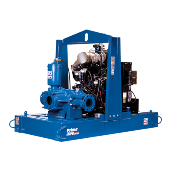
- Page 1 OM-07138-01 October 18, 2017 INSTALLATION, OPERATION, AND MAINTENANCE MANUAL WITH PARTS LIST PA SERIESr PUMP MODEL PA4E71C-3TNV88F FT4-ESP GORMAN‐RUPP PUMPS www.grpumps.com 2017 Gorman‐Rupp Pumps Printed in U.S.A.
- Page 2 Register your new Gorman‐Rupp pump online at www.grpumps.com Valid serial number and e‐mail address required. The engine exhaust from this product contains chemicals known to the State of California to cause cancer, birth defects or other reproductive harm. RECORD YOUR PUMP MODEL AND SERIAL NUMBER Please record your pump model and serial number in the spaces provided below.
-
Page 3: Table Of Contents
TABLE OF CONTENTS INTRODUCTION ..........PAGE I - 1 SAFETY ‐... - Page 4 TABLE OF CONTENTS (continued) Engine Oil ............. PAGE C - COLD WEATHER PRESERVATION .
-
Page 5: Introduction
PA SERIES OM-07138 INTRODUCTION Thank You for purchasing a Gorman‐Rupp pump. HAZARD AND INSTRUCTION Read this manual carefully to learn how to safely DEFINITIONS install and operate your pump. Failure to do so could result in personal injury or damage to the The following are used to alert maintenance per... -
Page 6: Safety - Section A
PA SERIES OM-07138 SAFETY ‐ SECTION A This information applies to Prime Aire forming any maintenance. Failure to do Series pumps. Refer to the manual ac so may result in serious personal injury. companying the engine before attempt ing to begin operation. - Page 7 OM-07138 PA SERIES hose connections are tight, properly fingers or tools, causing severe injury to supported and secure before operation. personnel. Make sure the pump is level. Lower jack Do not operate the pump against a stands and chock the wheels, if so closed discharge valve.
-
Page 8: Installation - Section B
PA SERIES OM-07138 INSTALLATION - SECTION B Review all SAFETY information in Section A. configuration, and priming must be tailored to the specific application. Since the pressure supplied Since pump installations are seldom identical, this to the pump is critical to performance and safety,... -
Page 9: Battery Installation
OM-07138 PA SERIES c. Carefully read all tags, decals, and markings sion. Connect and tighten the positive cable first, on the pump assembly, and perform all duties then the negative cable. indicated. Note that the pump shaft rotates in the required direction. -
Page 10: Suction And Discharge Piping
PA SERIES OM-07138 to secure them when filled with liquid and under pressure. Gauges If the pump has been mounted on a mov able base, do not attempt to operate the The pump is drilled and tapped for installing dis... -
Page 11: Sealing
OM-07138 PA SERIES Sealing air to escape from the liquid before it is drawn into the suction inlet. Since even a slight leak will affect priming, head, If two suction lines are installed in a single sump, and capacity, especially when operating with a... -
Page 12: Discharge Lines
PA SERIES OM-07138 Figure 2. Recommended Minimum Suction Line Submergence vs. Velocity DISCHARGE LINES Siphoning If the application involves a high discharge head, gradually close the discharge Do not terminate the discharge line at a level lower than that of the liquid being pumped unless a si... -
Page 13: Float Switch Installation
OM-07138 PA SERIES Float Switch Installation pipe is available, attach the float switch cable to the standpipe in the sump at the approxi mate desired liquid level. The Float Switch autostart system employs either a single or double float switch, where a bulb raises or lowers (floats) with the liquid level, thus activating b. - Page 14 PA SERIES OM-07138 that the liquid in the priming chamber never fully Next, install a drain line between the pump drain freezes. and the wet well or sump. This line must remain submerged in the liquid below the pump down lev...
-
Page 15: Operation - Section C
OM-07138 PA SERIES OPERATION - SECTION C OPERATION Review all SAFETY information in Section A. Make sure the pump is level. Lower jack Follow the instructions on all tags, labels and stands and chock the wheels, if so decals attached to the pump. -
Page 16: Operation In Extreme Heat
OM-07138 PA SERIES and fittings tight to maintain maximum pump effi ciency. Pump Vacuum Check Never tamper with the governor to gain more power. The governor establishes Read the vacuum gauge with the pump primed safe operating limits that should not be and at operation speed. -
Page 17: Stopping
OM-07138 PA SERIES vacuum suction gauge readings regularly to detect strainer blockage. Never introduce air or steam pressure into the Never disconnect any of the safety shut pump casing or piping to remove a blockage. This down features; this will void the warran... -
Page 18: Engine Fuel Filter
OM-07138 PA SERIES Engine Fuel Filter solids by flushing with a hose. Operate the pump for approximately one minute; this will remove any Consult the manual accompanying the engine, remaining liquid that could freeze the pump rotat and change the fuel filter periodically as indicated. - Page 19 OM-07138 PA SERIES TROUBLESHOOTING - SECTION D Review all SAFETY information in Section A. 5. Close the suction and discharge valves. 6. Vent the pump slowly and cau tiously. 7. Drain the pump. Before attempting to open or service the pump: 1.
- Page 20 OM-07138 PA SERIES TROUBLE POSSIBLE CAUSE PROBABLE REMEDY Check strainer and clean if neces Strainer clogged. PUMP STOPS OR FAILS TO DELIVER sary. RATED FLOW OR Check and clean check valve. Discharge check valve clogged. PRESSURE (cont.) Suction intake not submerged at Check installation and correct proper level or sump too small.
- Page 21 OM-07138 PA SERIES TROUBLE POSSIBLE CAUSE PROBABLE REMEDY BEARINGS RUN Bearing temperature is high, but Check bearing temperature regu TOO HOT within limits. larly to monitor any increase. Low or incorrect lubricant. Check for proper type and level of lubricant.
- Page 22 OM-07138 PA SERIES Preventive Maintenance Schedule Service Interval* Item Daily Weekly Monthly Semi‐ Annually Annually General Condition (Temperature, Unusual Noises or Vibrations, Cracks, Leaks, Loose Hardware, Etc.) Pump Performance (Gauges, Speed, Flow) Bearing Lubrication Seal Lubrication (And Packing Adjustment, If So Equipped) V‐Belts (If So Equipped)
- Page 23 OM-07138 PA SERIES PUMP MAINTENANCE AND REPAIR - SECTION E MAINTENANCE AND REPAIR OF THE WEARING PARTS OF THE PUMP WILL MAINTAIN PEAK OPERATING PERFORMANCE. STANDARD PERFORMANCE FOR PUMP MODEL PA4E71C-3TNV88F FT4-ESP Based on 70 F (21 C) clear water at sea level Contact the Gorman‐Rupp Company to verify per...
- Page 24 OM-07138 PA SERIES PARTS PAGE ILLUSTRATION Figure 1. Pump Model PA4E71C-3TNV88F FT4-ESP PAGE E - 2 MAINTENANCE & REPAIR...
- Page 25 OM-07138 PA SERIES Pump Model PA4E71C-3TNV88F FT4-ESP PARTS LIST (From S/N1689600 Up) If your pump serial number is followed by an “N”, your pump is NOT a standard production model. Contact the Gorman‐Rupp Company to verify performance or part numbers.
- Page 26 OM-07138 PA SERIES ILLUSTRATION Figure 2. Pump Model PA4E71C-3TNV88F FT4-ESP (Cont'd) PAGE E - 4 MAINTENANCE & REPAIR...
- Page 27 OM-07138 PA SERIES 9ump Model PA4E71C-3TNV88F FT4-ESP (Cont'd) PARTS LIST ITEM PART NAME PART ITEM PART NAME PART NUMBER NUMBER PUMP END ASSY 46133-447 PUMP DRAIN ASSY 46346-322 YANMAR 3TNV88F FT4 29239-064 BATTERY 12V SEE OPTIONS BASE/FUEL TANK ASSY 41553-043 24150...
- Page 28 OM-07138 PA SERIES ILLUSTRATION Figure 3. Pump Assembly PAGE E - 6 MAINTENANCE & REPAIR...
- Page 29 OM-07138 PA SERIES Pump Assembly PARTS LIST ITEM PART NAME PART ITEM PART NAME PART NUMBER NUMBER PUMP END ASSEMBLY 46133-382 VALVE BRACKET 34518-028 13000 PRIMING CHAMBER KIT 48275-005 SEAL/BRG CAVITY DRAIN 46342-045 STREET ELBOW RS08 11999 HEX NUT D04 15991...
- Page 30 OM-07138 PA SERIES ILLUSTRATION Figure 4. Pump End Assembly PAGE E - 8 MAINTENANCE & REPAIR...
- Page 31 OM-07138 PA SERIES Pump End Assembly PARTS LIST ITEM PART PART NAME NUMBER PUMP CASING SEE NOTE BELOW REPAIR ROTATING ASSY 44163-475 PIPE PLUG P12 15079 PIPE PLUG P08 15079 O‐RING 25152-273 SHIM SET 13130-3 17040 O‐RING S1674 LOCK WASHER...
- Page 32 OM-07138 PA SERIES ILLUSTRATION Figure 5. Repair Rotating Assembly PAGE E - 10 MAINTENANCE & REPAIR...
- Page 33 OM-07138 PA SERIES PARTS LIST Repair Rotating Assembly ITEM PART PART NAME NUMBER IMPELLER 38615-108 1102H CARTRIDGE SEAL ASSEMBLY 46513-151 IMPELLER ADJ SHIM SET 37J 17090 SHAFT SLEEVE O‐RING 25154-022 SEAL PLATE 38272-234 1102H SEAL PLATE GASKET 10959G 20000 OIL SEAL...
- Page 34 OM-07138 PA SERIES ILLUSTRATION Figure 6. Priming Chamber Kit PARTS LIST ITEM PART PART NAME NUMBER PRIMING CHAMBER ASSY 46112-709 PIPE BUSHING AP1608 15070 STREET ELBOW RS08 11999 BALL VALVE 26631-052 STUD C0809 15991 HEX NUT D08 15991 LOCK WASHER...
- Page 35 OM-07138 PA SERIES ILLUSTRATION Figure 7. Priming Chamber Assembly PARTS LIST ITEM PART PART NAME NUMBER PRIMING VALVE 26664-007 -ORIFICE BUTTON 26688-021 HEX HD CAPSCREW B0806 15991 LOCKWASHER J08 15991 PRIMING VALVE GASKET 38683-657 19060 PRIMING CHAMBER 38343-020 10000 STRAINER ASSY...
- Page 36 OM-07138 PA SERIES ILLUSTRATION Figure 8. Drive Assembly PARTS LIST ITEM PART PART NAME NUMBER SPROCKET 24271-122 COUPLING ASSY 24391-114 LOCK WASHER 21171-511 CAPSCREW 22645-164 SOC HD CAPSCR EW 22644-211 N0604 15990 BUSHING 24131-595 BUSHING 24131-039 PAGE E - 14...
- Page 37 OM-07138 PA SERIES ILLUSTRATION Figure 9. Seal and Bearing Cavity Drains ITEM PART PART NAME NUMBER 90_ SWIVEL ELBOW 26571-042 SWIVEL 26523-042 HOSE CLAMP 26518-642 3/8” ID x 10-1/2” LG. HOSE 18513-054 SHUTOFF VALVE 26661-407 STREET ELBOW RS06 11999 STREET ELBOW...
- Page 38 OM-07138 PA SERIES ILLUSTRATION Figure 10. Air Compressor Assembly PAGE E - 16 MAINTENANCE & REPAIR...
- Page 39 OM-07138 PA SERIES Air Compressor Assembly PARTS LIST ITEM PART PART NAME NUMBER CURTIS TOLEDO COMPRESSOR 26813-113 PIPE CAP V04 15079 PIPE NIPPLE T0428 15079 STREET ELBOW RS04 11999 HYDRAULIC HOSE ADAPTER 26813-952 GROMMET 27135-101 FAN GUARD ASSEMBLY 34851-513 15120...
- Page 40 OM-07138 PA SERIES PUMP AND SEAL DISASSEMBLY unit. Therefore, it is the responsibility of the owner/maintenance personnel to AND REASSEMBLY ensure that only safe, established main tenance procedures are used, and that Review all SAFETY information in Section A. any procedures not addressed in this Follow the instructions on all tags, label and de...
- Page 41 OM-07138 PA SERIES separate the priming chamber assembly, gasket good working condition and of suffi (8) and baffle (9) from the spool (52, Figure 3). cient capacity and that they are posi tioned so that loads will be balanced (Figure 7) and the pump or components will not be Remove the hardware (2 and 3) securing the prim...
- Page 42 OM-07138 PA SERIES ing. When the casing is fully drained, clean and re See Figure 1 and remove the air intake cover as install the pipe plug. sembly (35) from the base (3). Support the pump end using a hoist and sling,and remove the hard...
- Page 43 OM-07138 PA SERIES Loosening Impeller Impeller Removal (Figure 5) (Figure 4) With the rotating assembly removed from the With the pump end separated from the engine, pump casing, unscrew the impeller (1) from the wedge a block of wood between the vanes of the shaft (25).
- Page 44 OM-07138 PA SERIES should be performed only in a properly bearings. This may scratch the balls or equipped shop by qualified personnel. races and cause premature bearing fail ure. Disengage the hardware (18 and 19) and remove Rotate the bearings by hand to check for rough...
- Page 45 OM-07138 PA SERIES the shield facing toward the impeller end of the sembled bearings into the bearing housing until shaft. Position the outboard bearing (23) on the the retaining ring on the outboard bearing seats shaft with the retaining ring on the bearing O.D. to...
- Page 46 OM-07138 PA SERIES (175 in. lbs. or 2 m. kg.). Install the cog belt (12, Fig Using a suitable lifting device, position the as ure 3) over the sprocket and slide it up through the sembled drive and rotating assembly so the flex...
- Page 47 OM-07138 PA SERIES Seal Reassembly and Installation must be completely clean before installing the seal. (Figures 5, 12, 13 and 14) Most cleaning solvents are toxic and A new seal assembly should be installed flammable. Use them only in a well ven...
- Page 48 OM-07138 PA SERIES than the O.D. of the shaft. To ease installation, the NOTE tubing wall should be as thin as possible. The A firm resistance will be felt as the impeller presses length should be long enough to cover the threads the stationary seat into the seal plate bore.
- Page 49 OM-07138 PA SERIES Handle the seal parts with extreme care to prevent damage. Be careful not to contaminate precision finished faces; even fingerprints on the faces can shorten seal life. If necessary, clean the faces with a The shaft and impeller threads must be non‐oil based solvent and a clean, lint‐free tissue.
- Page 50 OM-07138 PA SERIES grease. Clean any scale or debris from the contact Discharge Check Valve Reassembly and ing surfaces in the pump casing that might inter Installation fere or prevent a good seal with the suction adap (Figure 3) tor.
- Page 51 OM-07138 PA SERIES chamber assembly on the hopper spool (not larly through the sight gauge (15A) and maintain it shown). Secure the priming chamber assembly at the midpoint of the gauge. When lubrication is with the hardware (6 and 7).
- Page 52 For Warranty Information, Please Visit www.grpumps.com/warranty or call: U.S.: 419-755-1280 Canada: 519-631-2870 International: +1-419-755-1352 GORMAN‐RUPP PUMPS...
Need help?
Do you have a question about the PA Series and is the answer not in the manual?
Questions and answers