PT-FRZ60 Model No. PT-FRZ50 Thank you for purchasing this Panasonic product. ■ The Operating Instructions
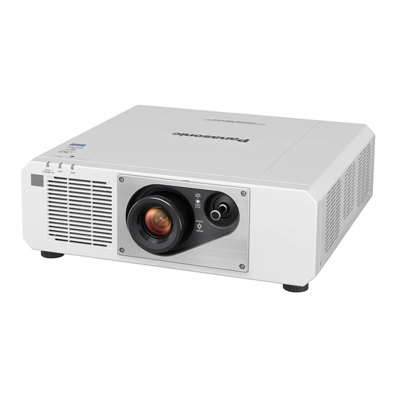
 corresponds to the firmware's main version 1.02 and higher. ■ This manual is common to all the models regardless of suffixes of the Model No.
Contents Contents Read this first! Operating with the remote control Using the shutter function Chapter 1 Preparation Using the mute function Adjusting the volume Precautions for use Using the freeze function Intended use of the product Using the on-screen display function Lens protection material Using the automatic setup function Cautions when transporting...
Page 3
Contents Changing the display language [CONTROL DEVICE PASSWORD CHANGE] [DISPLAY OPTION] menu [NETWORK] menu [COLOR MATCHING] [ETHERNET TYPE] [COLOR CORRECTION] [DIGITAL LINK] [SCREEN SETTING] [WIRED LAN] [AUTO SIGNAL] [PROJECTOR NAME] [AUTO SETUP] [NETWORK STATUS] [COMPUTER IN/OUT] [ADMINISTRATOR ACCOUNT] [HDMI IN] [NETWORK SECURITY] [DIGITAL LINK IN] [NETWORK CONTROL]...
Page 4
Read this first! Read this first! WARNING: THIS APPARATUS MUST BE EARTHED. WARNING: To prevent damage which may result in fire or shock hazard, do not expose this appliance to rain or moisture. This device is not intended for use in the direct field of view at visual display workplaces. To avoid incommoding reflexions at visual display workplaces this device must not be placed in the direct field of view.
Page 5
Read this first! WARNING: Do not look at the light emitted from the lens while the projector is being used. As with any bright source, do not stare into the direct beam, RG2 IEC 62471-5:2015. Indicated on the projector Notice on laser This projector is the Class 1 laser product that complies with IEC/EN 60825-1:2014.
Page 6
FCC NOTICE (USA) Supplier’s Declaration of Conformity Model Number: PT-FRZ60W / PT-FRZ60B / PT-FRZ50W / PT-FRZ50B Trade Name: Panasonic Responsible Party: Panasonic Corporation of North America Address: Two Riverfront Plaza, Newark, NJ 07102-5490 General Contact: http://www.panasonic.com/support Projector Contact: https://panasonic.net/cns/projector/ This device complies with Part 15 of the FCC Rules.
Page 7
L or colored RED. How to replace the fuse: Open the fuse compartment with a screwdriver and replace the fuse. Importer’s name and address within the European Union Panasonic Marketing Europe GmbH Panasonic Testing Centre Winsbergring 15, 22525 Hamburg, Germany...
Page 8
Read this first! r Hazard distance (IEC 62471-5:2015) The distance from the projection lens surface, at which the level of exposure has reached the level of the applicable Exposure Limit Value, is known as the hazard distance (HD) or safety distance. Do not look into the projected light from inside the hazard distance (within RG3 range).
Page 9
Read this first! WARNING: r POWER The wall outlet or the circuit breaker shall be installed near the equipment and shall be easily accessible when problems occur. If the following problems occur, cut off the power supply immediately. Continued use of the projector in these conditions will result in fire or electric shock, or will cause visual impairment.
Page 10
If liquid enters inside of the projector, consult your dealer. f Particular attention must be paid to children. Use the ceiling mount bracket specified by Panasonic. Using the ceiling mount bracket other than the specified one will result in falling accidents.
Page 11
Read this first! CAUTION: r POWER When disconnecting the power cord, be sure to hold the power plug and power connector. If the power cord itself is pulled, the lead will become damaged, and fire, short-circuits or serious electric shocks will result.
Page 12
Read this first! To remove the battery Remote Control Battery 1. Press the guide and lift the cover. 2. Remove the batteries. (ii) 12 - ENGLISH...
Page 13
Read this first! Brazil Only Brasil Apenas r Manuseio de baterias usadas BRASIL Após o uso, as pilhas e/ou baterias deverão ser entregues ao estabelecimento comercial ou rede de assistência técnica autorizada. Cobrir os terminais positivo (+) e negativo (-) com uma fita isolante adesiva, antes de depositar numa caixa destinada para o recolhimento.
Page 14
Trademarks f SOLID SHINE is a trademark of Panasonic Corporation. f DLP and the DLP logo are registered trademarks or trademarks of Texas Instruments. f Windows, Internet Explorer, and Microsoft Edge are registered trademarks or trademarks of Microsoft Corporation in the United States and other countries.
Page 15
Features of the Projector Quick Steps For details, refer to the corresponding pages. 1. Set up the projector. High luminance and high contrast ( x page 30) ▶ With a unique optical system which uses a new-generation laser light source, and 2.
Chapter 1 Preparation — Precautions for use Precautions for use Intended use of the product The product is intended to project still/moving image signals from video equipment and computers onto a screen. Lens protection material Lens protection material is attached to the product at the time of purchase to protect the projection lens from the vibration during transport.
Page 18
Chapter 1 Preparation — Precautions for use r Ask a qualified technician or your dealer for the installation work such as installing to a ceiling, etc. To ensure projector performance and safety, ask a qualified technician or your dealer when installing to a ceiling or in a high place.
Panasonic takes no responsibility for any damage to the product caused by an inappropriate choice of location for installing the projector, even if the warranty period of the product has not expired.
Chapter 1 Preparation — Precautions for use f Change your password periodically. f Panasonic Corporation or its affiliate companies will never ask for your password directly. Do not divulge your password in case you receive such inquiries. f The connecting network must be secured by a firewall, etc.
Page 21
Chapter 1 Preparation — Precautions for use r Do not touch the surface of the projection lens with your bare hands. If the surface of the projection lens becomes dirty from fingerprints or anything else, this will be magnified and projected onto the screen.
Chapter 1 Preparation — Precautions for use Accessories Make sure that the following accessories are provided with your projector. Numbers enclosed in < > show the number of accessories. Wireless remote control unit <1> (TXFSX01RWDZ) (N2QAYA000223) 100 V - 120 V For India (1JP1FRZ50BD) <1>...
The model numbers of optional accessories are subject to change without prior notice. f The optional accessories compatible with the projector may be added or changed without prior notice. For the latest information, visit the Panasonic website (https://panasonic.net/cns/projector/). ENGLISH - 23...
Chapter 1 Preparation — About your projector About your projector Remote control Front Bottom Power < v / b > button 11 <AUTO SETUP> button Sets the projector to the state where the projector is turned Automatically adjusts the image display position while projecting off (standby mode) when the <MAIN POWER>...
Chapter 1 Preparation — About your projector f Observe the following instructions that are indicated on the caution label at the back of the remote control: g Do not use old battery with new one. g Do not use batteries other than the type specified. g Be sure the batteries are inserted properly.
Page 26
Chapter 1 Preparation — About your projector Bottom Projection direction Remote control signal receiver (front) [AUTO], the luminance of the installed environment is detected by the luminance sensor to automatically perform appropriate picture Power indicator <ON (G)/STANDBY (R)> quality correction. Indicates the status of the power.
Page 27
Chapter 1 Preparation — About your projector r Connecting terminals <VIDEO IN> terminal <LAN> terminal This is a terminal to input video signal. This is the LAN terminal to connect to the network. <COMPUTER 1 IN> terminal <AUDIO IN 1> terminal This is a terminal to input the RGB signal, YC signal, This is a terminal to input audio signal.
Chapter 1 Preparation — Preparing the remote control Preparing the remote control Inserting and removing the batteries (ii) Fig. 1 Fig. 2 Open the cover. (Fig. 1) Insert the batteries and close the cover (insert the m side first). (Fig. 2) f When removing the batteries, perform the steps in reverse order.
Chapter 2 Getting Started — Setting up Setting up Usable outlet This projector supports AC 110 V (for Taiwan) or AC 100 V to AC 240 V (for other countries or regions) as the power supply. A grounded outlet supporting 15 A is required with either voltage. The shape of the usable outlet differs depending on the power supply.
Chapter 2 Getting Started — Setting up Portrait setting and projecting forward Portrait setting and projecting from rear (Using the translucent screen) Menu item Setting value Menu item Setting value [FRONT/REAR] [FRONT] [FRONT/REAR] [REAR] Set in accordance with the image Set in accordance with the image [FLOOR/CEILING] [FLOOR/CEILING]...
Page 32
Chapter 2 Getting Started — Setting up Projected image Screen L (LW/LT) L (LW/LT) Screen (Unit: m) L (LW/LT) Projection distance Projected image height Projected image width Distance from the lens center to the bottom edge of the projected image Projected image size *1 LW: Minimum projection distance LT: Maximum projection distance...
Page 33
Chapter 2 Getting Started — Setting up Arc center Arc center Screen Screen Projection distance Projection distance Arc radius Arc radius Only [CURVED CORRECTION] Only [KEYSTONE] used [KEYSTONE] and [CURVED CORRECTION] used together used Vertical Horizontal Vertical Horizontal keystone keystone keystone keystone Min.
Chapter 2 Getting Started — Connecting Connecting Before connecting f Before connecting, carefully read the operating instructions for the external device to be connected. f Turn off the power of all devices before connecting cables. f Take note of the following points before connecting the cables. Failure to do so may result in malfunctions. g When connecting a cable to a device connected to the projector or the projector itself, touch any nearby metallic objects to eliminate static electricity from your body before performing work.
Chapter 2 Getting Started — Connecting Note f Switching of the setting in the [DISPLAY OPTION] menu → [HDMI IN] → [EDID SELECT] may be required depending on the connected external device when HDMI signal is input. f For the HDMI cable, use an HDMI High Speed cable that conforms to the HDMI standards. However, when the following 4K video signal exceeding the supported transmission speed of the HDMI High Speed cable is to be input, use the HDMI cable supporting the high speed transmission of 18 Gbps such as the one with Premium HDMI cable authentication.
Chapter 2 Getting Started — Connecting Connecting example using DIGITAL LINK Twisted-pair-cable transmitter based on the communication standard HDBaseT such as the optional DIGITAL LINK output supported device (Model No.: ET-YFB100G, ET-YFB200G) uses the twisted pair cable to transmit input images, audio, Ethernet, and serial control signal, and the projector can input such digital signal to the <DIGITAL LINK/LAN>...
Page 37
(https://panasonic.net/cns/projector/). Note that the verification for devices of other manufacturers has been made for the items set by Panasonic Corporation, and not all the operations have been verified. For operation or performance problems caused by the devices of other manufacturers, contact the respective manufacturers.
Chapter 3 Basic Operations — Switching on/off the projector Switching on/off the projector Connecting the power cord Make sure that the supplied power cord is securely fixed to the projector body to prevent it from being removed easily. Confirm that the <MAIN POWER> switch is on the <OFF> side before connecting the power cord. Use the power cord matching with the power supply voltage and the shape of the outlet.
Chapter 3 Basic Operations — Switching on/off the projector Indicator status Projector status The power is switched off. (standby mode) Projection will start when the power < v / b > button is pressed. f The setting of the projector is as follows. g The [PROJECTOR SETUP] menu →...
Chapter 3 Basic Operations — Switching on/off the projector Press the power < v / b > button. f The power indicator <ON (G)/STANDBY (R)> lights green and the image is soon projected on the screen. Note f A warm-up period of up to approximately five minutes may be necessary until an image is displayed when the projector is switched on at around 0 °C (32 °F).
Page 42
Chapter 3 Basic Operations — Switching on/off the projector Initial setting (installation setting) Set [FRONT/REAR] and [FLOOR/CEILING] in [PROJECTION METHOD] depending on the installation mode. Refer to “Installation mode” ( x page 30) for details. After completed the initial setting, you can change the setting from the [PROJECTOR SETUP] menu → [PROJECTION METHOD].
Page 43
Chapter 3 Basic Operations — Switching on/off the projector INITIAL SETTING 16:10 SCREEN FORMAT SCREEN POSITION Set as necessary for the screen in use. CHANGE ENTER Press as to select [SCREEN POSITION]. INITIAL SETTING 16:9 SCREEN FORMAT SCREEN POSITION Set as necessary for the screen in use. MENU SELECT CHANGE ENTER...
STORE Please set the user name and password. if not set, could not use the Web Control function and for communication control via a LAN (including Panasonic application software). MENU SELECT SUB MENU ENTER [PASSWORD POLICY] Displays the policies about the password for the administrator account.
Chapter 3 Basic Operations — Switching on/off the projector Setting the administrator account Set the user name and password of the administrator account. Press as to select [USER NAME], and press the <ENTER> button. f The [USER NAME] screen is displayed. f The factory default setting of user name is "dispadmin".
Chapter 3 Basic Operations — Switching on/off the projector Turn the focus ring to roughly adjust the focus of the projected image. ( x page 49) Change the setting of the [PROJECTOR SETUP] menu → [PROJECTION METHOD] depending on the installation mode.
Page 47
Chapter 3 Basic Operations — Switching on/off the projector f Even when the power < v / b > button is pressed and the projector is switched off, the projector consumes power if the main power of the projector is on. When the [PROJECTOR SETUP] menu →...
Chapter 3 Basic Operations — Projecting Projecting Check the external device connection ( x page 34) and the power cord connection ( x page 39), and turn on the power ( x page 40) to start projection. Select the image to project, and adjust appearance of the projected image.
Chapter 3 Basic Operations — Projecting Switching the input by displaying the input selection screen The input for projection can be selected by displaying the input selection screen using the <INPUT SELECT> button on the control panel. Press the <INPUT SELECT> button on the control panel. f The input selection screen is displayed.
Chapter 3 Basic Operations — Projecting Turn the lens shift lever clockwise to fix. Adjust the zoom and the focus. (Fig. 2) f Adjust the size of the projected image by turning the zoom ring. f Adjust the focus by turning the focus ring. Note f It is recommended that images be projected continuously for at least 30 minutes before the focus is adjusted.
Chapter 3 Basic Operations — Operating with the remote control Operating with the remote control Using the shutter function If the projector is not used for a certain period of time during the meeting intermission, for example, it is possible to turn off the image and audio temporarily.
Chapter 3 Basic Operations — Operating with the remote control Adjusting the volume Adjust the volume of audio output. button Press the <VOL-> button/<VOL+> button on the remote control. <VOL+> Increases the volume. <VOL-> Decreases the volume. Note f This operation can be also performed using qw on the control panel. Using the freeze function The projected image can be paused and audio can be turned off regardless of the playback of the external device.
Chapter 3 Basic Operations — Operating with the remote control Using the automatic setup function The image position when the HDMI signal is input, or the resolution, clock phase, and image position when the analog RGB signal is input can be adjusted automatically. (Analog RGB signal is a signal structured with dots just like the computer signal.) It is recommended to input an image with bright white borders at the edges and high-contrast black and white characters when the automatic adjustment is being performed.
Chapter 3 Basic Operations — Operating with the remote control Switching the image aspect ratio Switch the image aspect ratio according to the input. button Press the <ASPECT> button. f The setting will change each time you press the button. Note f Refer to the [POSITION] menu →...
Chapter 3 Basic Operations — Operating with the remote control STATUS PROJECTOR TYPE PT-FRZ50 SERIAL NUMBER SW1234567 PROJECTOR RUNTIME LIGHT RUNTIME CONTINUOUS LIGHTING TIME 1h 23min MAIN/SUB VERSION 1.00 / 1.00 INTAKE AIR TEMP. 31°C/87°F OPTICS MODULE TEMP. 27°C/80°F EXHAUST AIR TEMP. 31°C/87°F LIGHT TEMP.
Page 56
Chapter 3 Basic Operations — Operating with the remote control Attention f Since the ID number of the remote control can be set without the projector body, do not press the <ID SET> button on the remote control carelessly. If the <ID SET> button is pressed and no number (<0> - <9>) buttons are pressed within five seconds, the ID number returns to its original value before the <ID SET>...
Chapter 4 Settings — Menu navigation Menu navigation The on-screen menu (Menu) is used to perform various settings and adjustments of the projector. Navigating through the menu Operating procedure button Press the <MENU> button on the remote control or control panel. f The [MAIN MENU] screen is displayed.
Chapter 4 Settings — Menu navigation Press as to select a sub-menu, and press qw or the <ENTER> button to change or adjust settings. f Some items will switch in order as follows each time you press qw . f For some items, press qw to display an individual adjustment screen with a bar scale as shown below. CONTRAST ADJUST Note...
Chapter 4 Settings — Menu navigation Main menu item Page [ADVANCED MENU] [DISPLAY LANGUAGE] [DISPLAY OPTION] [PROJECTOR SETUP] [TEST PATTERN] [SIGNAL LIST] [SECURITY] [NETWORK] Sub-menu The sub-menu of the selected main menu item is displayed, and you can set and adjust items in the sub-menu. [PICTURE] Sub-menu item Factory default...
Page 61
Chapter 4 Settings — Menu navigation Sub-menu item Factory default Page [FRAME RESPONSE] [NORMAL] [RASTER POSITION] ― *1 Depends on the signal input. Note f The factory default setting varies depending on the selected input terminal. [DISPLAY LANGUAGE] Details ( x page 78) [DISPLAY OPTION] Sub-menu item Factory default...
Chapter 4 Settings — [PICTURE] menu [PICTURE] menu On the menu screen, select [PICTURE] from the main menu, and select an item from the sub-menu. Refer to “Navigating through the menu” ( x page 58) for the operation of the menu screen. [PICTURE MODE] You can switch to the desired picture mode suitable for the image source and the environment in which the projector is used.
Chapter 4 Settings — [PICTURE] menu [COLOR] You can adjust the color saturation of the projected image. Press as to select [COLOR]. Press qw or the <ENTER> button. f The [COLOR] individual adjustment screen is displayed. Press qw to adjust the level. Operation Adjustment Range of adjustment...
Chapter 4 Settings — [PICTURE] menu Press as to select [WHITE BALANCE]. Press the <ENTER> button. f The [WHITE BALANCE] screen is displayed. Press as to select [WHITE BALANCE HIGH] or [WHITE BALANCE LOW]. Press the <ENTER> button. f The [WHITE BALANCE HIGH] screen or the [WHITE BALANCE LOW] screen is displayed. Press as to select [RED], [GREEN], or [BLUE].
Chapter 4 Settings — [PICTURE] menu Operation Adjustment Range of adjustment Press w . Brightness of the white part gets stronger. 0 - +10 Press q . The image becomes more natural. [GAMMA] You can switch gamma mode. Press as to select [GAMMA]. Press qw or the <ENTER>...
Chapter 4 Settings — [PICTURE] menu Operation Adjustment Range of adjustment Press w . Contours become sharper. 0 - +15 Press q . Contours become softer. Note f If you press w while the adjustment value is [+15], the value will become [0]. If you press q while the adjustment value is [0], the value will become [+15].
Chapter 4 Settings — [PICTURE] menu Terminal System format Select [AUTO], [NTSC], [NTSC4.43], [PAL], [PAL-M], [PAL-N], [SECAM], or [PAL60]. <VIDEO IN> terminal, Select [AUTO] normally. ([AUTO] will automatically determine from [NTSC], [NTSC4.43], [PAL], <COMPUTER 1 IN> terminal [PAL-M], [PAL-N], [SECAM], or [PAL60].) Switch the setting to the appropriate TV signal format.
Chapter 4 Settings — [POSITION] menu [POSITION] menu On the menu screen, select [POSITION] from the main menu, and select an item from the sub-menu. Refer to “Navigating through the menu” ( x page 58) for the operation of the menu screen. Note f When the optional DIGITAL LINK output supported device (Model No.: ET-YFB100G, ET-YFB200G) is connected to the <DIGITAL LINK/ LAN>...
Chapter 4 Settings — [POSITION] menu Identifies the video ID (VID) embedded in the video signal, and automatically switches the image size [AUTO] between 4:3 and 16:9. This is enabled when 480/60i or 480/60p signal is input. [THROUGH] Displays images without changing the resolution of the input signals. Displays images with the aspect ratio converted to 16:9 when standard signals are input .
Chapter 4 Settings — [POSITION] menu Press the <ENTER> button. f The [ZOOM] screen is displayed. Press as to select [MODE]. Press qw to switch the item. [INTERNAL] Enlarges the size within the aspect range set with [SCREEN FORMAT]. [FULL] Enlarges or reduces the size using the entire display area set with [SCREEN FORMAT].
Page 72
Chapter 4 Settings — [POSITION] menu Setting [KEYSTONE] or [CURVED CORRECTION] Press as to select [SCREEN ADJUSTMENT]. Press qw to select [KEYSTONE] or [CURVED CORRECTION]. Press the <ENTER> button. f The [KEYSTONE] or [CURVED CORRECTION] screen is displayed. Press as to select the item to adjust. Press qw to adjust.
Page 73
Chapter 4 Settings — [POSITION] menu Setting [CORNER CORRECTION] Press as to select [SCREEN ADJUSTMENT]. Press qw to select [CORNER CORRECTION]. Press the <ENTER> button. f The [CORNER CORRECTION] screen is displayed. Press as to select the item to adjust, and press the <ENTER> button. Press asqw to adjust.
Chapter 4 Settings — [ADVANCED MENU] menu [ADVANCED MENU] menu On the menu screen, select [ADVANCED MENU] from the main menu, and select an item from the sub- menu. Refer to “Navigating through the menu” ( x page 58) for the operation of the menu screen. [DIGITAL CINEMA REALITY] The picture quality is enhanced by raising the vertical resolution higher by performing the cinema processing when 576/50i signal for PAL (or SECAM), 480/60i signal for NTSC, or 1080/50i or 1080/60i signal is input.
Chapter 4 Settings — [ADVANCED MENU] menu [INPUT RESOLUTION] You can adjust the image to achieve an optimal image when there is a flickering image or smeared outlines. Press as to select [INPUT RESOLUTION]. Press the <ENTER> button. f The [INPUT RESOLUTION] screen is displayed. Press as to select [TOTAL DOTS], [DISPLAY DOTS], [TOTAL LINES], or [DISPLAY LINES], and press qw to adjust each item.
Page 76
Chapter 4 Settings — [ADVANCED MENU] menu Press qw to switch to [ON]. Press as to select [START] or [WIDTH]. Press qw to adjust the starting position or correction width. Press as to select [MARKER]. Press qw to switch to [ON]. f A marker for image position adjustment is displayed.
Chapter 4 Settings — [ADVANCED MENU] menu 23) Press the <ENTER> button. f The [OVERLAPPED BLACK LEVEL] screen is displayed. f [RED], [GREEN], and [BLUE] can be adjusted individually if [INTERLOCKED] is set to [OFF]. 24) Press as to select an item, and press qw to adjust the setting. [BLACK BORDER WIDTH] (Right) Projection range Edge blending [WIDTH] (Right)
Chapter 4 Settings — [DISPLAY LANGUAGE] menu [DISPLAY LANGUAGE] menu On the menu screen, select [DISPLAY LANGUAGE] from the main menu, and display the sub-menu. Refer to “Navigating through the menu” ( x page 58) for the operation of the menu screen. Changing the display language You can select the language of the on-screen display.
Chapter 4 Settings — [DISPLAY OPTION] menu [DISPLAY OPTION] menu On the menu screen, select [DISPLAY OPTION] from the main menu, and select an item from the sub- menu. Refer to “Navigating through the menu” ( x page 58) for the operation of the menu screen. [COLOR MATCHING] Correct the color difference between projectors when using multiple projectors simultaneously.
Chapter 4 Settings — [DISPLAY OPTION] menu Press the <ENTER> button. f The [MEASURED MODE] screen is displayed. Press as to select [MEASURED DATA]. Press the <ENTER> button. f The [MEASURED DATA] screen is displayed. Measure the current luminance (Y) and the chromaticity coordinates (x, y) using the colorimeter. Press as to select a color, and press qw to adjust the setting.
Chapter 4 Settings — [DISPLAY OPTION] menu Press as to select [SCREEN POSITION]. f [SCREEN POSITION] cannot be selected or adjusted when [SCREEN FORMAT] is set to [16:10]. Press qw to adjust [SCREEN POSITION]. [AUTO SIGNAL] Set whether to execute automatic setup of signals automatically. The screen display position or signal level can be adjusted automatically without pressing the <AUTO SETUP>...
Chapter 4 Settings — [DISPLAY OPTION] menu [ON] Adjust the screen position and size when automatic setup is executed. [OFF] Does not perform automatic adjustment. Adjusting signal level automatically Press as to select [AUTO SETUP]. Press the <ENTER> button. f The [AUTO SETUP] screen is displayed. Press as to select [SIGNAL LEVEL ADJUST].
Page 83
Chapter 4 Settings — [DISPLAY OPTION] menu Setting [EDID MODE] in [COMPUTER IN/OUT] (COMPUTER1 input/COMPUTER2 input) Press as to select [COMPUTER IN/OUT]. Press the <ENTER> button. f The [COMPUTER IN/OUT] screen is displayed. Press as to select [EDID MODE] of [COMPUTER1] or [COMPUTER2]. Press the <ENTER>...
Chapter 4 Settings — [DISPLAY OPTION] menu Note f [COMPUTER2 SELECT] cannot be set when the COMPUTER2 input is selected. [HDMI IN] Set this item in accordance with the video signal input to the <HDMI 1 IN> terminal or the <HDMI 2 IN> terminal. Setting [SIGNAL LEVEL] in [HDMI IN] Press as to select [HDMI IN].
Chapter 4 Settings — [DISPLAY OPTION] menu Press the <ENTER> button. f The [HDMI1] screen or the [HDMI2] screen is displayed. Press qw to switch the item. f The items will switch each time you press the button. [DEFAULT] Standard setting. [SCREEN FIT] Changes the EDID data according to the [SCREEN FORMAT] setting.
Page 86
Chapter 4 Settings — [DISPLAY OPTION] menu Setting [EDID SELECT] in [DIGITAL LINK IN] Press as to select [DIGITAL LINK IN]. Press the <ENTER> button. f The [DIGITAL LINK IN] screen is displayed. Press as to select [EDID SELECT] of [DIGITAL LINK IN]. Press qw to switch the item.
Chapter 4 Settings — [DISPLAY OPTION] menu Note f Settings in [RESOLUTION] and [VERTICAL SCAN FREQUENCY] are displayed in the [DIGITAL LINK IN] screen. f Setting of the resolution and the vertical scanning frequency may be necessary on the computer or video device in use. f The computer, video device, or projector in use may require the power to be turned off and on again after setting.
Page 88
Chapter 4 Settings — [DISPLAY OPTION] menu Sets to yellow. Sets to blue. Sets to white. Sets to green. Sets to peach. Sets to brown. Setting [OSD MEMORY] Set hold for the position of the menu screen (OSD) cursor. Press as to select [ON-SCREEN DISPLAY]. Press the <ENTER>...
Chapter 4 Settings — [DISPLAY OPTION] menu Note f If [OFF] is set, the warning message will not be displayed on the projected image even when warning condition such as [TEMPERATURE WARNING] is detected while using the projector. Also, the following countdown message is not displayed: the message until the power is turned off after the no signal lights-out function is executed;...
[USER LOGO] Displays the image registered by the user. Note f To create and register the [USER LOGO] image, use “Logo Transfer Software”. The software can be downloaded from the Panasonic website (https://panasonic.net/cns/projector/). [STARTUP LOGO] Set the logo display when the power is turned on.
Chapter 4 Settings — [DISPLAY OPTION] menu Press the <ENTER> button. f The [UNIFORMITY] screen is displayed. Press as to select [FULL SCREEN CORRECTION]. Press qw to switch the item. [OFF] Does not perform correction using a computer. [ON] Performs correction for the brightness and color unevenness of the entire screen using a computer. *1 Advanced skills are necessary to use computer control correction.
Chapter 4 Settings — [DISPLAY OPTION] menu Press the <ENTER> button. f The [SHUTTER SETTING] screen is displayed. Press as to select [SHUTTER]. Press the <ENTER> button. f Press the <MENU> button to cancel the function. Note f The power indicator <ON (G)/STANDBY (R)> will blink green slowly while the shutter function is in use (shutter: closed). f To output audio while the shutter function is in use (shutter: closed), set the [PROJECTOR SETUP] menu →...
Chapter 4 Settings — [DISPLAY OPTION] menu Image displayable area Image position Select “Select line (luminance)” on the waveform monitor. Adjust black level. f Adjust the black level 0 % of the video signal to the 0 % position of the waveform monitor using the [PICTURE] menu →...
Chapter 4 Settings — [PROJECTOR SETUP] menu [PROJECTOR SETUP] menu On the menu screen, select [PROJECTOR SETUP] from the main menu, and select an item from the sub- menu. Refer to “Navigating through the menu” ( x page 58) for the operation of the menu screen. [PROJECTOR ID] The projector has an ID number setting function that can be used when multiple projectors are used side by side to enable simultaneous control or individual control via a single remote control.
Chapter 4 Settings — [PROJECTOR SETUP] menu [ECO MANAGEMENT] Set the operation method of the projector. Setting [OPERATING MODE] Press as to select [ECO MANAGEMENT]. Press the <ENTER> button. f The [ECO MANAGEMENT] screen is displayed. Press as to select [OPERATING MODE]. Press qw to switch the item.
Chapter 4 Settings — [PROJECTOR SETUP] menu f When [CONSTANT MODE] is set to [AUTO] or [PC] PT-FRZ60 PT-FRZ50 [LIGHT OUTPUT] (%) Estimated runtime Estimated runtime Brightness (lm) Brightness (lm) (hour) (hour) 50.0 3 000 20 000 2 600 20 000 41.1 2 500 24 000...
Page 97
Chapter 4 Settings — [PROJECTOR SETUP] menu Setting [NO SIGNAL SHUT-OFF] This is a function to automatically set the power of the projector to standby mode when there is no input signal for specific period. The time before switching to standby can be set. Press as to select [ECO MANAGEMENT].
Chapter 4 Settings — [PROJECTOR SETUP] menu f [QUICK STARTUP] cannot be set when [STANDBY MODE] is set to [ECO]. f When [QUICK STARTUP] is set to [ON], the power consumption during standby becomes high during the period when the [QUICK STARTUP] function is valid.
Page 99
Chapter 4 Settings — [PROJECTOR SETUP] menu Press qw to switch the item. f The items will switch each time you press the button. [OFF] Does not correct the brightness of the screen by the brightness sensor. Corrects the brightness of the screen by the brightness sensor. [AUTO] When the brightness of light source or white balance changes, the brightness of the projected image is automatically corrected.
Page 100
Chapter 4 Settings — [PROJECTOR SETUP] menu f If the projector is operating with [CONSTANT MODE] set to [AUTO] or [PC], brightness and color cannot be measured when the shutter function is enabled (shutter: closed) within approximately eight minutes after the light source is turned on. Therefore, brightness may be corrected after approximately 30 seconds have elapsed after the shutter function is disabled (shutter: open).
Page 101
Chapter 4 Settings — [PROJECTOR SETUP] menu BRIGHTNESS CONTROL STATUS LINK GROUP A PROJECTOR 192. 168. 30. 2 192. 168. 30. 3 PROJECTOR2 PROJECTOR3 192. 168. 30. 4 UPDATE MENU SELECT When [CONSTANT MODE] is set to [PC] BRIGHTNESS CONTROL STATUS CONSTANT MODE PROJECTOR RETURN...
Chapter 4 Settings — [PROJECTOR SETUP] menu g Are there devices with the same IP address on the network? g Are LAN cables connected correctly? ( x page 131) g Are the subnets of the projectors the same? g Are the same [LINK] settings applied to a group? f Refer to [PROJECTOR NAME] ( x page 122) or “[Network config] page”...
Page 103
Chapter 4 Settings — [PROJECTOR SETUP] menu Note f The [STANDBY MODE] setting will be forced to [NORMAL] when the [PROJECTOR SETUP] menu → [ECO MANAGEMENT] → [STANDBY MODE] is set to [ECO], and [SCHEDULE] is set to [ON]. Changing the setting to [ECO] is not available. The [STANDBY MODE] setting will not change back even when [SCHEDULE] is set to [OFF] in this condition.
Switches the input to DIGITAL LINK. Switches the input to DIGITAL LINK, and switches the input of the [INPUT1] - [INPUT10] Panasonic twisted-pair-cable transmitter to the specified input. [NORMAL] Prioritizes luminance. Controls the power to increase the life of the light source although [ECO] the luminance is lower than that of [NORMAL].
Sets the input to HDMI2. [DIGITAL LINK] Sets the input to DIGITAL LINK. Sets the input to DIGITAL LINK, and switches the input of the Panasonic twisted-pair-cable transmitter [INPUT1] - [INPUT10] to the specified input. *1 When the optional DIGITAL LINK output supported device (Model No.: ET-YFB100G, ET-YFB200G) is connected to the projector, its input name is automatically reflected from [INPUT1] to [INPUT10].
Chapter 4 Settings — [PROJECTOR SETUP] menu [SYSTEM SELECTOR] Switches the [SYSTEM SELECTOR] setting. ( x page 67) [DAYLIGHT VIEW] Switches the [DAYLIGHT VIEW] setting. ( x page 66) [WAVEFORM MONITOR] Displays the waveform of the input signal. ( x page 92) Press the <ENTER>...
Chapter 4 Settings — [PROJECTOR SETUP] menu Press the <ENTER> button. f The [AUDIO SETTING] screen is displayed. Press as to select [IN SHUTTER]. Press qw to switch the item. f The items will switch each time you press the button. [OFF] No audio is output while using the shutter function (shutter: closed).
Chapter 4 Settings — [PROJECTOR SETUP] menu Note f Power supply function is disbled in [ECO] standby mode even when [DC OUT] is set to [ON]. f When an external device exceeding the rating (DC 5 V, maximum 2 A) is connected to the <DC OUT> terminal while this function is set to [ON], an error is detected and the power supply will be stopped.
Chapter 4 Settings — [PROJECTOR SETUP] menu f If any abnormality has occurred on the projector, press the <DEFAULT> button while the [STATUS] screen is displayed to display the detail screen of the error information. f For details on the contents displayed in [SELF TEST], refer to “[SELF TEST] indications” ( x page 165). [DATE AND TIME] Set the time zone, date, and time of the built-in clock of the projector.
Chapter 4 Settings — [PROJECTOR SETUP] menu Press the <ENTER> button. f The [SECURITY PASSWORD] screen is displayed. Enter a security password and press the <ENTER> button. When the confirmation screen is displayed, press qw to select [OK], and press the <ENTER> button. f [PROGRESS] is displayed while saving data.
Page 111
Chapter 4 Settings — [PROJECTOR SETUP] menu Press the <ENTER> button. f The HDMI-CEC operation screen is displayed. Select the item displayed on the HDMI-CEC operation screen to operate the device. f Refer to the “Using HDMI-CEC function” ( x page 152) for the operation details. Note f If no CEC-compatible device is connected to <HDMI 1 IN>...
Chapter 4 Settings — [PROJECTOR SETUP] menu Press the <ENTER> button. f The [HDMI CEC] screen is displayed. -> Press as to select [DEVICE PROJECTOR]. Press qw to switch the item. f The items will switch each time you press the button. Disables the link control from the CEC-compatible device to the projector.
Chapter 4 Settings — [TEST PATTERN] menu [TEST PATTERN] menu On the menu screen, select [TEST PATTERN] from the main menu. Refer to “Navigating through the menu” ( x page 58) for the operation of the menu screen. [TEST PATTERN] Display the test pattern built-in to the projector.
Chapter 4 Settings — [SIGNAL LIST] menu [SIGNAL LIST] menu On the menu screen, select [SIGNAL LIST] from the main menu. Refer to “Navigating through the menu” ( x page 58) for the operation of the menu screen. r Registered signal details Memory number: A1 (1-2) Sub memory number...
Chapter 4 Settings — [SIGNAL LIST] menu Note f A registered signal can also be deleted from [REGISTERED SIGNAL DELETE] on the [REGISTERED SIGNAL SETUP] screen. Protecting the registered signal Press asqw to select the signal to protect. Press the <ENTER> button. f The [REGISTERED SIGNAL STATUS] screen is displayed.
Chapter 4 Settings — [SIGNAL LIST] menu f When a registration signal is deleted, the settings are also deleted. f In an environment where multiple types of signals are input to the same terminal, signals are sometimes not determined correctly when the setting is set to [WIDE].
Chapter 4 Settings — [SECURITY] menu [SECURITY] menu On the menu screen, select [SECURITY] from the main menu, and select an item from the sub-menu. Refer to “Navigating through the menu” ( x page 58) for the operation of the menu screen. f When the projector is used for the first time Initial password: Press awsqawsq in order, and press the <ENTER>...
[USER LOGO] Displays the image registered by the user. Note f To create and register the [USER LOGO] image, use “Logo Transfer Software”. The software can be downloaded from the Panasonic website (https://panasonic.net/cns/projector/). [TEXT CHANGE] Edit the text to be displayed when [TEXT] is selected in [DISPLAY SETTING].
Chapter 4 Settings — [SECURITY] menu Press as to select [CONTROL PANEL] or [REMOTE CONTROL]. Press qw to switch [USER]. Press as to select the button item to set. f When [INPUT SELECT BUTTON] is selected in [REMOTE CONTROL], press the <ENTER> button, and then press as to select the button to set.
Chapter 4 Settings — [NETWORK] menu [NETWORK] menu On the menu screen, select [NETWORK] from the main menu, and select an item from the sub-menu. Refer to “Navigating through the menu” ( x page 58) for the operation of the menu screen. [ETHERNET TYPE] Set the path for transmitting the Ethernet signal.
Page 121
Chapter 4 Settings — [NETWORK] menu For DIGITAL LINK ― [AUTO] For long reach ― For Ethernet ― ― ― [DIGITAL LINK] ― [LONG REACH] ― [ETHERNET] ― ― ― *1 Communication via a twisted-pair-cable transmitter is not available. Connect the projector to the network directly. Note f For the signal with the resolution of 1 920 x 1 200 dots or less, the maximum transmission distance is 100 m (328'1") when connected with the DIGITAL LINK communication method.
Chapter 4 Settings — [NETWORK] menu Select this item when connecting the optional DIGITAL LINK output supported device (Model No.: [OFF] ET-YFB100G, ET-YFB200G) to the <DIGITAL LINK/LAN> terminal. Select this item when connecting the “XTP transmitter” of Extron Electronics to the <DIGITAL LINK/ [ON] LAN>...
Chapter 4 Settings — [NETWORK] menu [DHCP] Displays the status of use of the DHCP server. [IP ADDRESS] Displays the [IP ADDRESS]. [SUBNET MASK] Displays the [SUBNET MASK]. [DEFAULT GATEWAY] Displays the [DEFAULT GATEWAY]. [DNS1] Displays the address of the preferred DNS server. [DNS2] Displays the address of the alternate DNS server.
Page 124
Chapter 4 Settings — [NETWORK] menu f The password cannot be blank. After entering the password, press asqw to select [OK], and press the <ENTER> button. f The [ADMINISTRATOR ACCOUNT] screen is displayed. Press as to select [PASSWORD CONFIRM], and press the <ENTER> button. f The [PASSWORD CONFIRM] screen is displayed.
Chapter 4 Settings — [NETWORK] menu f Enter a new password. f Up to 16 characters can be entered. f Enter the current password if you do not want to change it. 14) After entering the password, press asqw to select [OK], and press the <ENTER> button. f The [ADMINISTRATOR ACCOUNT] screen is displayed.
Chapter 4 Settings — [NETWORK] menu Note f When [COMMAND PROTECT] is set to [DISABLE], connection authentication is not performed, making it vulnerable to threats on the network. Be aware of the risks before making settings. f For details on how to use the command control function, refer to "Control commands via LAN". ( x page 172) [NETWORK CONTROL] Set the network control of this projector.
Page 127
Chapter 4 Settings — [NETWORK] menu f The [PJLink PASSWORD] screen is displayed. Press as to select [PASSWORD] under [NEW], and press the <ENTER> button. f The [PASSWORD] screen is displayed. Press asqw to select a character, and press the <ENTER> button. f Enter a new password.
Chapter 4 Settings — [NETWORK] menu [Art-Net] Set the Art-Net function. Setting the password of the administrator account ( x page 123) is required for using the Art-Net function of the projector. Note f If the password of the administrator account has not been set, that is, if it is left blank, the network function of this projector cannot be used. Set a password before using the web control function or the communication control (including operation with application software) via LAN.
Page 129
Chapter 4 Settings — [NETWORK] menu [USER] Changes the channel assignment. Uses the channel assignment with DZ21K series compatible. DZ21K series: DZ21K series, DS20K series, DW17K series, DZ16K series f When [2] or [1] is selected, the function assigned to the channel is displayed by pressing the <ENTER> button.
For details, visit the Panasonic website (https://panasonic.net/cns/projector/). f PJLink Operation or status query of the projector can be performed from a computer using the PJLink protocol.
Page 132
(https://panasonic.net/cns/projector/). Note that the verification for devices of other manufacturers has been made for the items set by Panasonic Corporation, and not all the operations have been verified. For operation or performance problems caused by the devices of other manufacturers, contact the respective manufacturers.
Page 133
Chapter 5 Operations — Network connection Setting the projector Connect the projector to a computer using a LAN cable. Turn on the power of the projector. Press the <MENU> button to open the [NETWORK] menu from the main menu. f The [NETWORK] screen is displayed. Press as to select [WIRED LAN], and press the <ENTER>...
Chapter 5 Operations — Web control function Web control function Following operation is possible from a computer using the web control function. f Setting and adjustment of the projector f Display of the projector status f Sending E-mail messages when there is a problem with the projector The projector supports “Crestron Connected”, and the following application software of Crestron Electronics, Inc.
Page 135
Chapter 5 Operations — Web control function f A password consisting of at least three of the following four character types is recommended. g Uppercase letters g Lowercase lettters g Digits g Symbols (~!@#$%^&*()_+\|}{][<>.,/?`) In [Password(Retype)], Re-enter the password entered in Step 4). Click [Change].
Page 136
Chapter 5 Operations — Web control function Item Function Administrator Standard User Page [Basic control] [Projector control] [Detail control] ― [Network config] ― [Adjust clock] ― [Ping test] ― [Network security] ― [Detailed set up] [E-mail set up] ― [Authentication set up] ―...
Page 137
Chapter 5 Operations — Web control function [PROJECTOR TYPE] [LIGHT OUTPUT] Displays the type of the projector. Displays the setting status of [LIGHT OUTPUT]. [MAIN VERSION] 10 [INPUT] Displays the firmware version of the projector. Displays the status of the selected input. [POWER] 11 [INTAKE AIR TEMPERATURE] Displays the status of the power.
Page 138
Chapter 5 Operations — Web control function [Access error log] page Click [Status] → [Access error log]. The error log on the web server is displayed such as access to the pages that do not exist or access with unauthorized user names or passwords. [Mail error log] page Click [Status] →...
Page 139
Chapter 5 Operations — Web control function [Basic control] page Click [Projector control] → [Basic control]. [POWER] [SYSTEM] Turns off/on the power. Switches the system method. [SHUTTER] On-screen display of the projector Switches whether to use the shutter function (enabled (shutter: Displays the same items as shown on the on-screen display of closed)/disabled (shutter: open)).
Chapter 5 Operations — Web control function [Network config] page Click [Detailed set up] → [Network config]. f Click [Network config] to display the [CAUTION!] screen. f Click the [Next] button to display the current settings. f Click the [Change] button to display the setting change screen. Crestron tools Network security [PROJECTOR NAME]...
Page 141
Chapter 5 Operations — Web control function [Adjust clock] page Click [Detailed set up] → [Adjust clock]. Crestron tools Network security [Time Zone] set to adjust the date and time manually. Select the time zone. (To enter the server name, the DNS server needs to be set up.) [Set time zone] [Date] Updates the time zone setting.
Page 142
Chapter 5 Operations — Web control function [COMMAND PROTECT] [Submit] Make settings for the connection authentication when using the Updates the setting. command control function. If you click [Submit] with [DISABLE] selected in [COMMAND [DISABLE]: Connect to the projector in non-protected mode. PROTECT], a confirmation screen will be displayed.
Page 143
Chapter 5 Operations — Web control function Network security Network security Crestron tools Crestron tools [E-MAIL ADDRESS 1], [E-MAIL ADDRESS 2] value set at the above field. Enter the E-mail address to be sent. Leave [E-MAIL ADDRESS 2] [PERIODIC REPORT]: blank when two E-mail addresses are not to be used.
Page 144
Chapter 5 Operations — Web control function Network security Crestron tools [OPERATING MODE] [NO SIGNAL LIGHT-OUT] Select the [OPERATING MODE] setting. Select the duration until the light source is turned off when the no signal light-out function is used. [AUTO POWER SAVE] Set [ON] when setting [AMBIENT LIGHT DETECTION] and [NO [NO SIGNAL SHUT-OFF] SIGNAL LIGHT-OUT].
Page 145
Chapter 5 Operations — Web control function Contents of E-mail sent Example of the E-mail sent when E-mail is set The following E-mail is sent when the E-mail settings have been established. === Panasonic projector report(CONFIGURE) === Projector Type : PT-FRZ50 Serial No...
Page 146
Chapter 5 Operations — Web control function Example of the E-mail sent for an error The following E-mail is sent when an error has occurred. === Panasonic projector report(ERROR) === Projector Type : PT-FRZ50 Serial No : SW1234567 ----- Error information ----- H11 Intake air temp.
Page 147
Chapter 5 Operations — Web control function [Set up password] page (for administrator account) Click [Set up password]. [Administrator] [PJLink] Used to change the setting of the administrator account. Used to change the setting of the PJLink account. [User] [Next] Used to change the setting of the standard user account.
Page 148
Chapter 5 Operations — Web control function [Account] [OK] Displays the account to change. Determines the change of password. [New] [User name]: Enter the desired new user name. (Up to 16 characters in single byte) [Password]: Enter the desired new password. (Up to 16 characters in single byte) [Password(Retype)]: Enter the desired new password again.
Page 149
Chapter 5 Operations — Web control function [Set up password] (for standard user account) The password of the standard user account can be changed. [Old Password] [Retype] Enter the current password. Enter the desired new password again. [New Password] [OK] Enter the desired new password.
Chapter 5 Operations — Web control function [Tools] page Click [Tools] in the operation page. [Control System] Network status Set the information required for communicating with the controller Displays the settings of wired LAN. to be connected with the projector. [DHCP] Displays the current setting.
Page 151
Chapter 5 Operations — Web control function [Help] page Click [Help] in the operation page. The [Help Desk] window is displayed. [Help Desk] A message can be sent/received with the administrator using the Crestron Connected. ENGLISH - 151...
Chapter 5 Operations — Using HDMI-CEC function Using HDMI-CEC function HDMI-CEC function allows the basic operation of CEC-compatible device with the projector remote control or the link control between the projector and CEC-compatible device. Connecting a CEC-compatible device Connect a CEC-compatible device to the <HDMI 1 IN> terminal or <HDMI 2 IN> terminal. CEC-compatible device CEC-compatible device Blu-ray disc player (example)
Chapter 5 Operations — Using HDMI-CEC function Menu operation of CEC-compatible device When the setting menu of the CEC-compatible device is displayed, you can use the ▲▼◀▶ buttons and <ENTER> button of the remote control to operate the menu. About the link control By setting the [PROJECTOR SETUP] menu →...
The firmware of the projector can be updated via LAN. Check the Panasonic website (https://panasonic.net/cns/projector/pass/) for availability of the firmware that can be updated. Customer can update the firmware if a newer version than the current firmware version is published.
Page 155
When other software has started up or operating g When the computer has gone into sleep/pause status Acquiring the firmware Download the firmware update tool for this projector (compressed file in zip format) from the Panasonic website (https://panasonic.net/cns/projector/pass/). f File name (example): FirmUpdateTool_FRZ50_101.zip (Update tool for the PT-FRZ60/PT-FRZ50 with main version 1.01)
Page 156
Chapter 5 Operations — Updating the firmware File name (example): FirmUpdateTool_FRZ50_101.exe Double-click the executable file generated by extracting. f The update tool is started up, and the confirmation screen is displayed. PT-FRZ60 / FRZ50 / FRZ55 Confirm the status of the projector. f Confirm that the projector to be updated is in the standby mode.
Page 157
Chapter 5 Operations — Updating the firmware Click [Next]. f The connection setting screen is displayed. PT-FRZ60 / FRZ50 / FRZ55 1.01 Enter the setting details of the projector. f Enter the details set in the projector to be updated. Item Details [IP Address]...
Page 158
Chapter 5 Operations — Updating the firmware 10) Click [Start]. f Update is started. f The temperature indicator <TEMP> and the light source indicator <LIGHT> on the projector blink red alternately while updating. f Elapsed time and rough progress can be confirmed in the update status display screen. The required time is approximately 15 minutes.
Chapter 6 Maintenance — Light source/temperature indicators Light source/temperature indicators When an indicator lights up If a problem occurs inside the projector, the light source indicator <LIGHT> or the temperature indicator <TEMP> will inform you by lighting or blinking. Check the status of the indicators and take following measures. Attention f When switching off the projector to deal with problems, make sure to follow the procedure in “Switching off the projector”...
Page 161
Chapter 6 Maintenance — Light source/temperature indicators Temperature indicator <TEMP> Blinking red Blinking red Indicator status Lighting red (2 times) (3 times) Internal temperature is high Internal temperature is high Status Warm-up status The cooling fan has stopped. (warning). (standby status). f Did you turn on the power f Is the intake/exhaust vent blocked? Cause...
Chapter 6 Maintenance — Maintenance Maintenance Before maintaining the projector f Make sure to turn off the power before performing the maintenance of the projector. ( x pages 39, 46) f When switching off the projector, make sure to follow the procedures in “Switching off the projector” ( x page 46).
Chapter 6 Maintenance — Troubleshooting Troubleshooting Review the following points. For details, see the corresponding pages. Problems Points to be checked Page f Is the power plug firmly inserted into the outlet? ― f Is the <MAIN POWER> switch set to <OFF>? f Is the wall outlet supplying electricity? ―...
Page 164
Chapter 6 Maintenance — Troubleshooting Problems Points to be checked Page Video from HDMI f Is the HDMI cable connected securely? compatible device does f Turn the power of the projector and the external device off and on. ― not appear or it appears f Is a signal which is not compatible with the projector being input? jumbled.
Chapter 6 Maintenance — [SELF TEST] indications [SELF TEST] indications [SELF TEST] can be checked in the [PROJECTOR SETUP] menu → [STATUS] → [SELF TEST]. The following list shows the alphanumeric symbol that is displayed when an error or a warning has occurred and its details.
Page 166
Chapter 6 Maintenance — [SELF TEST] indications Note f The self-diagnosis display and the details of the malfunction may be different. f For errors and warnings that are not described in the table, consult your dealer. r Measure for error and warning Action Measure number...
Input selection list query 11 12 21 32 33 36 ― Returns the name set in the [NETWORK] menu → [PROJECTOR NAME? Projector name query xxxxx NAME]. Manufacturer name INF1? Panasonic Returns manufacturer name. query PT-FRZ60 INF2? Model name query Returns model name. PT-FRZ50 168 - ENGLISH...
Chapter 7 Appendix — Technical information Parameter/ Class Command Control details Remark response string Other information INF0? xxxxx Returns the main version of the firmware. queries CLSS? Class information query 2 Returns class for PJLink. SNUM ? Serial number query xxxxxxxxx Returns serial number.
Page 171
Chapter 7 Appendix — Technical information r SHUTTER Performance Parameter Default value SHUTTER: Open, mute clear 0-63 No operation 64-191 SHUTTER: Closed, mute 192-255 r FADE-IN, FADE-OUT (when [Art-Net CHANNEL SETTING] is set to [1]) Operate together with SHUTTER. Performance Parameter Default value 0-15...
“ENABLE / DISABLE” of channel 11 to “Disable” and then back to “Enable”. f To create and register the USER LOGO image, use “Logo Transfer Software”. The software can be downloaded from the Panasonic website (https://panasonic.net/cns/projector/).
Page 173
Chapter 7 Appendix — Technical information IP address Obtain from the [NETWORK] menu → [NETWORK STATUS]. Port number Obtain from the [NETWORK] menu → [NETWORK CONTROL] → [COMMAND PORT]. Check the response from the projector. Termination Data section Blank Mode Blank Random number section symbol...
Page 174
Chapter 7 Appendix — Technical information execute the network connection request every time the command is to be sent. For details, refer to “Communication flow between server and client” ( x page 175). When connecting in non-protected mode Connecting This is the connection method when [NETWORK] menu → [NETWORK SECURITY] → [COMMAND PROTECT] is set to [DISABLE].
Chapter 7 Appendix — Technical information Note f The projector will automatically disconnect the connection with the network right after sending the command. This is the specification based on the security view point to prevent unauthorized operation of this product by a malicious third party. To send commands continuously, execute the network connection request every time the command is to be sent.
Page 176
Chapter 7 Appendix — Technical information Pin assignments and signal names D-Sub 9-pin (female) Pin No. Signal name Details Outside view ― Transmitted data Received data ― Earth ― Connected internally ― Communication conditions (Factory default) Signal level RS-232C-compliant Sync. method Asynchronous Baud rate 9 600 bps...
Page 177
Chapter 7 Appendix — Technical information Basic format (has subcommands) Same as the basic format Sub command (5 bytes) Parameter (6 bytes) Symbol “+” or “–” (1 byte) and setting or adjustment value (5 bytes) Operation (1 byte) “=” (Set the value specified using parameter) *1 When transmitting a command which does not need a parameter, an operation (E) and parameter are not necessary.
Page 178
Chapter 7 Appendix — Technical information Parameter/response Command Details Remark (parameter) string VIDEO COMPUTER1 COMPUTER2 Switching the input signal HDMI1 HDMI2 DIGITAL LINK Shutter control OPEN Shutter status query CLOSE DEFAULT/VID AUTO/AUTO Aspect ratio switch 16:9 THROUGH HV FIT Aspect ratio settings H FIT query V FIT...
Chapter 7 Appendix — Technical information List of compatible signals The following table specifies the video signals compatible with the projector. f Symbols that indicate formats are as follows. g V: VIDEO, Y/C g R: RGB (analog) g Y: YC (analog) g H: HDMI g DL: DIGITAL LINK...
Page 180
Chapter 7 Appendix — Technical information Scanning freq. Plug and play Signal name Dot clock Resolution (SIGNAL freq. Format HDMI DIGITAL LINK Horizontal Vertical (Dots) COMPUTER FORMAT) (MHz) (kHz) (Hz) 4K/60P 4K/30P 2K 4K/60P 4K/30P 4 096 x 2 160 135.0 60.0 297.0...
Page 181
Chapter 7 Appendix — Technical information Scanning freq. Plug and play Signal name Dot clock Resolution (SIGNAL freq. Format HDMI DIGITAL LINK Horizontal Vertical (Dots) COMPUTER FORMAT) (MHz) (kHz) (Hz) 4K/60P 4K/30P 2K 4K/60P 4K/30P 1366 x 768/60 1 366 x 768 47.7 59.8 85.5...
Chapter 7 Appendix — Specifications Specifications The specifications of the projector are as follows. PT-FRZ60W, PT-FRZ60B, PT-FRZ60BD, PT-FRZ50W, 100 V - 240 V ~ (100 V - 240 V alternating current), 50 Hz/60 Hz Power supply PT-FRZ50B, PT-FRZ50BD PT-FRZ60BT, PT-FRZ50BT 110 V ~ (110 V alternating current), 60 Hz PT-FRZ60W, PT-FRZ60B, 540 W (5.8 A - 2.3 A)
Page 183
Chapter 7 Appendix — Specifications Operating environment 0 °C (32 °F) to 45 °C (113 °F) temperature Operating environment Operating environment 10 % to 80 % (no condensation) humidity Power supply DC 3 V (AAA/R03/LR03 battery x 2) Operating range Within approx.
Page 184
RGB input f Resolution: 640 x 400 to 1 920 x 1 200 f Dot clock frequency: 162 MHz or less f PIAS (Panasonic Intelligent Auto Scanning) system input f Resolution: 480i/576i to 1 920 x 1 080 f Dot clock frequency: 148.5 MHz or less f The HD/SYNC and VD terminals do not support 3 value SYNC.
Ask a qualified technician to do the installation work such as mounting the projector on the ceiling. f Panasonic takes no responsibility for any damage to the projector resulting from use of the Ceiling Mount Bracket not manufactured by Panasonic or the inappropriate choice of location for installing the Ceiling Mount Bracket, even if the warranty period of the projector has not expired.