Sign In
Upload
Manuals
Brands
IEI Technology Manuals
Touch Panel
PPC-F15C-Q370
IEI Technology PPC-F15C-Q370 Manuals
Manuals and User Guides for IEI Technology PPC-F15C-Q370. We have
1
IEI Technology PPC-F15C-Q370 manual available for free PDF download: User Manual
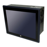
IEI Technology PPC-F15C-Q370 User Manual (146 pages)
Modular Panel PC with 8th Gen. LGA1151 Intel Core i7/i5/i3 and Pentium Processor, DDR4, HDMI, USB 3.2, Dual GbE, RS-232, M.2, Four SSD Bays, PCIe 3.0, RoHS Compliant
Brand:
IEI Technology
| Category:
Touch Panel
| Size: 5 MB
Table of Contents
Table of Contents
7
Introduction
19
Overview
20
Figure 1-1: PPC-Fxxc-Q370 Series Panel PC
20
Model Variations
21
Table 1-1: Model Variations
21
Features
22
Front Panel
22
Figure 1-2: Front Panel
22
Bottom Panel
23
Figure 1-3: Bottom Panel
23
Top Panel
24
Figure 1-4: Top Panel
24
Technical Specifications
25
15" ~ 17" Specifications
25
Table 1-2: Technical Specifications (15" ~ 17")
26
23.8" Specifications
27
Table 1-3: Technical Specifications (18.5" ~ 23.8")
28
Dimensions
29
PPC-F15C-Q370 Dimensions
29
Figure 1-5: PPC-F15C-Q370 Dimensions (Unit: MM)
29
PPC-FW15C-Q370 Dimensions
30
Figure 1-6: PPC-FW15C-Q370 Dimensions (Unit: MM)
30
PPC-F17C-Q370 Dimensions
31
Figure 1-7: PPC-F17C-Q370 Dimensions (Unit: MM)
31
PPC-FW19C-Q370 Dimensions
32
Figure 1-8: PPC-FW19C-Q370 Dimensions (Unit: MM)
32
PPC-FW22C-Q370 Dimensions
33
Figure 1-9: PPC-FW22C-Q370 Dimensions (Unit: MM)
33
PPC-FW24C-Q370 Dimensions
34
Figure 1-10: PPC-FW24C-Q370 Dimensions (Unit: MM)
34
Unpacking
35
Unpacking
36
Packing List
36
Optional Items
37
Table 2-1: Package List
37
Table 2-2: Optional Items
37
Installation
38
Anti-Static Precautions
39
Installation Precautions
39
Installation Procedure
40
Solid-State Drive Installation
41
Figure 3-1: Unlock HDD Cover
41
Figure 3-2: Drive Tray Removal
41
Figure 3-3: SSD Retention Screws
42
Figure 3-4: SSD Installation
42
Removing the Rear Cover
43
Figure 3-5: Rear Cover Retention Screw Removal
44
Figure 3-6: Remove the Rear Cover
44
DIMM Installation
45
Figure 3-7: DIMM Installation
45
Figure 3-8: DIMM Slot Locations
45
SSD Installation (Optional)
46
Figure 3-9: M.2 Slot Locations
46
Figure 3-10: Removing the M.2 Module Retention Screw
47
Figure 3-11: Inserting the M.2 Module into the Slot at an Angle
47
Expansion Card Installation (Optional)
48
Figure 3-12: Securing the M.2 Module
48
Figure 3-13: Pcie Slot Locations
49
Figure 3-14: Blank Bracket Screw Removal
49
Mounting the System
50
Panel Mounting
50
Figure 3-15: Install and Secure Expansion Card
50
Figure 3-16: PPC-F15C-Q370 Panel Cutout Dimensions
51
Figure 3-17: PPC-FW15C-Q370 Panel Cutout Dimensions
51
Figure 3-18: PPC-F17C-Q370 Panel Cutout Dimensions
51
Figure 3-19: PPC-FW19C-Q370 Panel Cutout Dimensions
52
Figure 3-20: PPC-FW22C-Q370 Panel Cutout Dimensions
52
Figure 3-21: PPC-FW24C-Q370 Panel Cutout Dimensions
52
Rack and Cabinet Installation
53
Figure 3-22: Tighten the Mounting Clamp Screws
53
Figure 3-23: the Rack/Cabinet Bracket
54
Figure 3-24: Secure the Rack/Cabinet Bracket
54
Figure 3-25: Install into a Rack/Cabinet
55
Com Port Connection
56
Figure 3-26: RS-232 Connector (COM1, COM2)
56
Table 3-1: RS-232 Connector Pinouts
56
Power-On Procedure
57
Installation Checklist
57
Figure 3-27: Power Button
57
Software Installation
58
Driver Download
58
Figure 3-28: IEI Resource Download Center
58
Raid Configuration
60
Figure 3-29: RAID Configuration-BIOS Setting
61
Bios
63
Introduction
64
Starting Setup
64
Using Setup
64
Getting Help
65
BIOS Menu Bar
65
Table 4-1: BIOS Navigation Keys
65
Main
66
Advanced
67
CPU Configuration
69
Thunderbolt Configuration
71
Trusted Computing
72
ACPI Settings
73
Iwdd H/W Monitor
74
Smart Fan Mode Configuration
75
F81866 Super IO Configuration
77
Serial Port N Configuration
78
RTC Wake Settings
79
Serial Port Console Redirection
80
Legacy Console Redirection Settings
83
USB Configuration
84
Nvme Configuration
85
Iei Qts
85
IEI Feature
86
Chipset
87
System Agent (SA) Configuration
88
Memory Configuration
89
Graphics Configuration
90
PEG Port Configuration
92
PCH-IO Configuration
94
PCI Express Configuration
96
SATA Configuration
99
HD Audio Configuration
101
Security
102
Boot
103
Save & Exit
105
Troubleshooting and Maintenance
106
C-Q370 System Maintenance Overview
107
System Troubleshooting
107
The System Doesn't Turn on
107
The System Doesn't Boot up
108
More Troubleshooting
108
Component Replacement
109
Interface Connectors
110
Peripheral Interface Connectors
111
Figure 6-1: Main Board Layout Diagram (Front Side)
111
Internal Peripheral Connectors
112
ATX Power Input Connector (ATX1)
113
Table 6-1: Peripheral Interface Connectors
113
Table 6-2: ATX Power Input Connector (ATX1) Pinouts
113
Additional Power Connector (ATXPWR1)
114
Battery Connector (BAT1)
114
Chassis Intrusion Connector (CHASSIS1)
114
CPU Power Connector (CPU12V1)
114
Table 6-3: Additional Power Connector (ATXPWR1) Pinouts
114
Table 6-4: Battery Connector (BAT1) Pinouts
114
Table 6-5: Chassis Intrusion Connector (CHASSIS1) Pinouts
114
Table 6-6: CPU Power Connector (CPU12V1)
114
DIO Connector (DIO1)
115
EC Debug Port (EC_DBG1)
115
Fan Connector, CPU (CPU_FAN1)
115
Table 6-7: DIO Connector (DIO1) Pinouts
115
Table 6-8: EC Debug Port (EC_DBG1) Pinouts
115
Table 6-9: CPU Fan Connector (CPU_FAN1) Pinouts
115
Fan Connectors, System (SYS_FAN1, SYS_FAN2, SYS_FAN3)
116
I 2 C Connector (I2C1)
116
Internal Displayport Connector (IDP1)
116
Table 6-10: System Fan Connectors (SYS_FAN1, SYS_FAN2, SYS_FAN3) Pinouts
116
Table 6-11: I 2 C Connector (I2C1) Pinouts
116
Table 6-12: Internal Displayport Connector (IDP1) Pinouts
116
LED Connector, HDD (H_LED1)
117
LED Connector, Power (P_LED1)
117
LVDS Connector (LVDS1)
117
Table 6-13: HDD LED Connector (H_LED1) Pinouts
117
Table 6-14: Power LED Connector (P_LED1) Pinouts
117
LVDS Backlight Connector (INV1)
118
Mini SAS Connector (MINI_SAS1)
118
Table 6-15: LVDS Connector (LVDS1) Pinouts
118
Table 6-16: LVDS Backlight Connector (INV1) Pinouts
118
Power Button Connector (P_BTN1)
119
Touch Panel Connector (TS1)
119
Table 6-17: Mini SAS Connector (MINI_SAS1) Pinouts
119
Table 6-18: Power Button Connector (P_BTN1) Pinouts
119
Table 6-19: Touch Panel Connector (TS1) Pinouts
119
Connector (COM2)
120
RS-422/485 Connector (COM3)
120
Smbus Connector (SMB1)
120
Table 6-20: RS-232 Connector (COM2) Pinouts
120
Table 6-21: RS-422/485 Connector (COM3) Pinouts
120
Table 6-22: Smbus Connector (SMB1) Pinouts
120
SPI Flash Connector (J_SPI1)
121
SPI Flash (EC) Connector (J_EC1)
121
Speaker Connector (SPK1)
121
Table 6-23: SPI Flash Connector (J_SPI1) Pinouts
121
Table 6-24: SPI Flash (EC) Connector (J_EC1) Pinouts
121
Table 6-25: Speaker Connector (SPK1) Pinouts
121
TPM Connector (TPM1)
122
USB 2.0 Connectors, Single (JUSB1, JUSB2)
122
Table 6-26: TPM Connector (TPM1) Pinouts
122
Table 6-27: Single USB 2.0 Connectors (JUSB1, JUSB2) Pinouts
122
USB 2.0 Connectors, Dual (JUSB3)
123
USB DOM Connector (USB_DOM1)
123
Jumpers
123
Table 6-28: Dual USB 2.0 Connector (JUSB3) Pinouts
123
Table 6-29: USB DOM Connector (USB_DOM1) Pinouts
123
Table 6-30: Jumpers
123
Clear CMOS Jumper (J_CMOS1)
124
ME RTC Register Setting Jumper (ME_RTC1)
124
Table 6-31: Clear CMOS Jumper (J_CMOS1) Settings
124
Table 6-32: ME RTC Register Jumper (ME_RTC1) Settings
124
A Regulatory Compliance
125
B Safety Precautions
130
Safety Precautions
131
General Safety Precautions
131
Anti-Static Precautions
132
Product Disposal
133
Maintenance and Cleaning Precautions
134
Maintenance and Cleaning
134
Cleaning Tools
134
CBIOS Menu Options
136
Bios Configuration Options
137
D Watchdog Timer
139
E Error Beep Code
142
Pei Beep Codes
143
Dxe Beep Codes
143
F Hazardous Materials Disclosure
144
Rohs II Directive (2015/863/EU)
145
China Rohs
146
Advertisement
Advertisement
Related Products
IEI Technology PPC-F15C-Q370-P/PC/25
IEI Technology PPC-F15C-Q370-i3/PC/25
IEI Technology PPC-F15C-Q370-i5/PC/25
IEI Technology PPC-F15C-Q370-i7/PC/25
IEI Technology PPC-F15B-BTi
IEI Technology PPC-F15B
IEI Technology PPC-F15D-ULT5-i5/4G/PC
IEI Technology PPC-F15D-ULT5-C/4G/PC
IEI Technology PPC-F15B-BTi-J1/2G/R-R10
IEI Technology PPC-F15B-BTi-J1/2G/PC-R10
IEI Technology Categories
Motherboard
Touch Panel
Computer Hardware
Single board computers
Desktop
More IEI Technology Manuals
Login
Sign In
OR
Sign in with Facebook
Sign in with Google
Upload manual
Upload from disk
Upload from URL