
Related Manuals for motortronics VMX2-18-BP


Summary of Contents for motortronics VMX2-18-BP
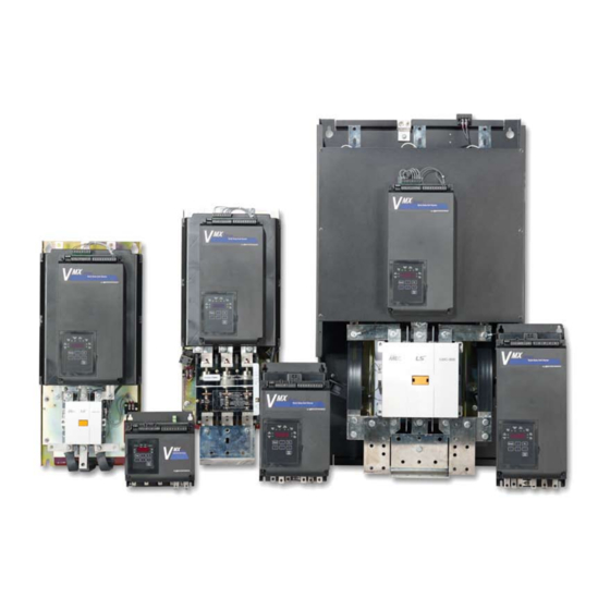
- Page 1 MO T O R T R O N I C S S o l i d S t a t e A C Mo t o r C o n t r o l V M X 2 V MX 2 S E R I E S C O MP A C T S O F T S T A R T E R 2 0 8 - 6 0 0 V , 9 - 1 2 5 0 A mp s , 5 - 1 2 0 0 H P U S E R MA N U A L...
-
Page 2: Table Of Contents
Table of Contents Page General Description ……………………….. Chapter 1 - Introduction Sizes and Ratings ………………………….. Receiving and Unpacking …………………. Chapter 2 - Installation Choosing a Location …………………..Initial Unit Inspection …………………..SERVICE WARNING! …………………….. Mounting and Cleaning ……………………. Power Terminations ……………………….. Remote Keypad Mounting………….... -
Page 3: Chapter 1 - Introduction
Chapter 1 - Introduction 1.1 General Description The VMX2 Series is a digitally programmable solid-state reduced voltage soft starter. Its six SCR design features a voltage/current ramp with an anti-oscillation circuit for smooth load acceleration. The SCRs are sized to withstand starting currents of 500% for 20 seconds (Standard Duty) and up to 500% for 60 seconds (Heavy Duty). - Page 4 1.1.2 Advanced Motor Protection Features A sophisticated Thermal Model of the motor operation is created in the Thermal Model Electronic microprocessor to accurately track all starting, stopping, and running conditions, Overload Protection thus, providing maximum motor protection. Two Stage Starting: Programmable for Class 5 through 30 Overload Curves Run: Programmable for Class 5 through 30 when "At-Speed"...
- Page 5 1.1.3 Design Specifications Type of Load: Three - phase AC induction motors. AC Supply Voltage: Universal, 208 - 600VAC ±10%, 50/60 Hz. Power Ratings: 9 - 1250 Amps, 7.5 - 1000 HP @ 460V. Unit Capacity - Continuous Max. Amp rating is UL Listed continuous rating. Unit Capacity - Overload Rating 500% - 60 seconds.
-
Page 6: Sizes And Ratings
Sizes and Ratings The Motortronics VMX2 Series starters are current rated controllers. Max. Amp ratings are for continuous duty and must not be exceeded. Always check the motor nameplate FLA and Service Factor to ensure proper sizing. Each size has an adjustable current range of 50% to 100% of the Max Amp rating. -
Page 7: Chapter 2 - Installation
Chapter 2 - Installation Receiving and Unpacking Upon receipt of the product, you should immediately do the following: ▪ Carefully unpack the unit from the shipping carton and inspect it for shipping damage. If damaged, notify the freight carrier and file a claim within 15 days of receipt. -
Page 8: Service Warning
SERVICE WARNING! Do not service equipment with voltage applied! The unit can be the source of fatal electrical shocks! To avoid shock hazard, disconnect main power and control power before working on the unit. Warning labels must be attached to terminals, enclosure and control panel to meet local codes. -
Page 9: Power Terminations
All line and load power terminations are to be made to the tin plated copper Bus Tabs located on each unit. Bus tabs are pre-drilled to accept industry standard bolts. Motortronics recommends using crimp- on ring lugs, although mechanical compression lugs are suitable as well. - Page 10 2.6 Power Connections (cont.) Figure 2.6.3 Critical clearances for bus tab connections Note: Consult factory for bus tab critical dimensions for units 210A and above VMX2 Series Digital Solid State Soft Starter User Manual P a g e...
-
Page 11: Remote Keypad Mounting
Suggested Model Current Range Wire Size Torque Size Torque Wire Size Number Min.- Max. in.-lbs. ISOmm VMX2-18-BP 9 - 18 VMX2-28-BP 14 - 28 1 x M5 (included) VMX2-39-BP 19 - 39 VMX2-48-BP 24 - 48 VMX2-62-BP 36 - 62... -
Page 12: Dimensions
Overall Mounting Weight Enclosure Model Number Inches Inches Inches Inches Inches Inches (mm) (mm) (mm) (mm) (mm) (mm) (kg) VMX2-18-BP through 8.85 8.00 6.65 8.06 7.00 0.22 VMX2-48-BP (230) (203) (169.7) (204.7) (177.8) (5.6) (5.9) VMX2-62-BP through 14.00 8.00 6.65 13.25... -
Page 13: Chapter 3 - Motor Overload Protection
Chapter 3 - Motor Overload Protection Solid State Overload Protection The VMX2 Series Starter provides true U.L. listed I t Thermal Overload MOTOR FLA (F001) Protection as a built-in function of the main digital processor for must be programmed maximum motor protection. It mimics the tripping action of a bi-metallic overload relay, with the accuracy and repeatability of a digital control for unit to operate! system. - Page 14 3.1.3 Disabling the Overload Protection The Overload Protection feature can be disabled if necessary. When using external devices such as Motor Protection Relays or when the VMX2 Series is wired downstream from an existing starter, this feature can be disabled to prevent conflicts with external Overload Protection devices.
-
Page 15: Nema Class Trip Curves
▪ 3.1.3.c Overload Protection During Bypass When an integral Bypass Contactor is used to shunt power around the SCRs in the VMX2 Series (as in the VMX…-BP version), overload protection is maintained as long as the VMX2 Series is directly controlling the contactor. No additional Overload Relay is necessary for normal operation. - Page 16 3.2.3 Running Overload Curve During the Run mode, Overload Trip curves are selectable from NEMA Class 5, 10, 15, 20, 25, and 30. Program the appropriate curve according to the characteristics of your motor and load. 3.2.4 Overload Trip Curve Chart Figure 3.2.4: VMX2 Series Overload Trip Curves VMX2 Series Digital Solid State Soft Starter User Manual 14 |...
-
Page 17: Chapter 4 - Connections
Chapter 4 - Connections Power Connections Disconnect Refer to national and local code for wire sizing and length, connect power conductors to the unit input terminals marked L1, L2, L3 (R, S, T Circuit for IEC users). Use appropriate compression or mechanical lugs for Breaker termination to these bus tabs. -
Page 18: Control Connections
4.1.4 Testing The VMX2 Series can be tested with a load smaller than the motor it was originally selected to control, however additional steps must be taken to avoid tripping on Phase Current Loss. See section 5.6.8.a under “Phase Loss Protection” for additional details on performing this task. - Page 19 4.2.1 AC Control Power Supply Connection 120VAC Separate AC Control Power supply is required to power the electronics Supply of the VMX2 Series starter. The standard is 120VAC, but 240VAC (optional) can be ordered if necessary for your line power supply A1 A2 configuration.
- Page 20 4.2.2 Three-Wire Control Connection For standard 3-wire control, connect dry (voltage free) contacts for the Stop / Start buttons as shown on the diagram directly above the terminal strip. Connect the N.O. contact of the Start button to Terminal 1 (far left terminal), the common point between the Stop and Start to Terminal 2 from left) and the N.C.
- Page 21 4.2.5 Enabling the Dual Ramp and Jog Features TB1 includes provisions for enabling the Dual Ramp and Jog functions by using external contact closures. Both features use a common +24VDC from Terminal 7. However, they can be used independently of each other or together.
- Page 22 4.2.6 Analog Output (4-20mA) The VMX2 Series starter provides a 4 to 20 milliamp output signal that can be set to monitor different parameter values using F108 and scaled with parameter F109 and F110. See section 5.5.16. ▪ 4.2.6.a External Overload Relay Connection If an external Overload Relay (OLR) is used (see Section 3.1.3.c and Appendix 4), connect the N.C.
- Page 23 Output 3 is a Form A, (SPST), N.O. contact. It is not necessary to use the programmable output auxiliary relays in the Start / Stop circuit. An internal seal-in relay is provided elsewhere (see 4.2.2.a). Motortronics recommends fusing all outputs with external fuses.
- Page 24 4.2.9 Bypass Contactor Control On VMX2…-BP version (and NEMA 12 enclosures) starters, an internal dedicated connection is used at the factory for automatically controlling the Bypass Contactor. Field wiring for Bypass Contactor operation is not required. ▪ 4.2.9.a Independent Bypass Contactor Control The VMX2…-BP Series starters use standard industrial contactors that can be controlled independently of the starter electronics if necessary.
-
Page 25: Chapter 5 - Programming
Chapter 5 - Programming Introduction It is best to operate the motor at its full load starting conditions to achieve the proper time, torque and ramp settings. Initial factory settings MOTOR FLA (F001) are set to accommodate general motor applications and provide basic must be programmed motor protection. -
Page 26: Display Modes
Display Modes There are three modes of display: The Status Display Mode, the Program Mode, and the Fault Mode. 5.3.1 Status Display Mode (Default Display) The Status Display Mode displays five “screens” of information. Motor Currents (3 phases), Remaining Thermal Capacity and Ground Current. This is also the entry screen for going into the Program Mode. -
Page 27: Program Mode
Program Mode The starter must be OFF (Motor Stopped) in order to enter the Program Mode. Use the Program Mode to view or change Function (Fn) settings. To enter the Program Mode, press the [Fn] key once from the Status Screen described in 5.3.1 above. - Page 28 5.4.2 Enabling Password Protection / Parameter Lock The VMX2 Series starter is shipped with the password protection disabled (F070 = 0). If it becomes necessary to prevent parameters from being changed inadvertently, set the password in function F070. See Appendix 3 for details. If the display reads [ Loc] when the [READ/ENTER] key is pressed, the parameter lock is enabled.
- Page 29 ▪ 5.4.3.a Changing a Value by Increments Although it may be easier to shift the cursor position, it is also possible to increase or decrease values by pressing the UP or DOWN arrow keys successively. This will change the Function value by the incremental amount associated with that Function.
-
Page 30: Fault Mode
5.4.5 Fault Mode The Fault Mode Display provides information to the operator when a fault occurs and allows the operator to review fault history. Refer to Section 7 for details. Fault codes are displayed by 3 alpha characters. The first and second characters (reading left to right) are the initials for the applicable English-language fault name. - Page 31 ▪ 5.4.5.c Automatic Reset The VMX2 Series starter provides for automatic reset on certain non-critical faults and Overload. For non-critical fault resets, see section 5.6.9.b for program details of F052. For automatic Overload reset, see section 3.1.3.b and 5.6.1 for programming details. ▪...
-
Page 32: The Vmx2 Function List
The VMX2 Function List 5.5.1 Motor FLA, Service Factor and Overload Protection Functions Setting Factory Password Fn # Group Function Description Adjustment / Display Range Section Increments Setting Level Motor Nameplate FLA 50 -100% of Max Amp Rating. Upper limit of range automatically F001 1 amp FLA must be programmed for... - Page 33 5.5.3 Jog Mode Functions Setting Factory Password Fn # Group Function Description Adjustment / Display Range Section Increments Setting Level F019 Voltage Jog 5 - 100% Line Voltage 5.6.3 F020 Time of Voltage Jog 1 - 20 Seconds 1 second seconds 4.2.5.b F021...
- Page 34 5.5.7 Line Voltage Setting Factory Password Fn # Group Function Description Adjustment / Display Range Section Increments Setting Level F029 Voltage Input 200 - 690 Volt F030 Voltage Imbalance Trip % 0, 1 - 30% [0=Disabled] 1(%) F031 Voltage Imbalance Trip Delay 1 - 20 seconds F032 Over Voltage Trip %...
- Page 35 5.5.9 Lockouts, Reset and Internal Protection Functions Setting Factory Password Fn # Group Function Description Adjustment / Display Range Section Increments Setting Level Coast Down (Back Spin) 0 - 60 minutes F048 1 minute Lockout Timer [0 = Disabled] Disabled 0 - 10 starts F049 Maximum Starts per Hour...
- Page 36 5.5.11 Serial Communications Setting Factory Password Fn # Group Function Description Adjustment / Display Range Section Increments Setting Level 0 = Disabled F065 Communications 1 = Enabled (11Bit) 2 = Enabled (10Bit) F066 Baud Rate 4.8, 9.6 and 19.2 KB 3 rates 9.6 KB F067...
- Page 37 5.5.13 Fault History and Run Time Setting Factory Password Fn # Group Function Description Adjustment / Display Range Section Increments Setting Level 0 = No fault history, or F085 Fault History #1, Latest Fault Fault # 1 - 57: see Fault code list Time Stamp, Fault #1 00.0 23.59 (hh.mm)
- Page 38 5.5.15 Motor Power Protection Settings Setting Factory Password Fn # Group Function Description Adjustment / Display Range Section Increments Setting Level 0 - 2 0 = Disabled F102 Motor kW Trip 1 = Over kW Trip 2 = Under kW Trip F103 Motor kW Trip Point 20 - 100% of full load KW...
-
Page 39: Function Descriptions
Function Descriptions Your VMX2 Series starter is set at the factory with typical default settings that perform well in most applications. Following are detailed descriptions of each Function and the factory default settings. 5.6.1 Motor and Overload Function Descriptions F001= Motor FLA Factory Setting = 0 Range = 50 - 100% of Unit Max. - Page 40 F004 = Overload Class During Run Factory Setting = 10 (Class 10) Range = 5 - 30 NEMA / UL Class Set value according to the instructions provided by your motor / equipment manufacturer. This trip curve will not be enabled until the motor has reached full speed.
-
Page 41: Starting Modes
5.6.2 Starting Modes The VMX2 Series is capable of several different starting modes, but is set from the factory for the most common applications. A second ramp profile is available for use should it be required. Unless wired to do so, the VMX2 Series defaults to Ramp 1. - Page 42 F011 = Initial Voltage of Ramp 1 Factory Setting = 60% Range = 0 - 100% Sets the initial voltage of Ramp 1 when F010 = 1 or 3. The initial voltage level should be set to provide just enough torque to make the motor shaft begin to rotate while preventing torque shock damage to mechanical components.
- Page 43 ▪ 5.6.2.a Ramp 2 (user-optional ramp) This ramp is selected by closing the input for Ramp 2, TB1 - terminals 5 & 6 (see section 4.2.5). If this input is left open, the VMX2 Series will respond only to Ramp 1 settings as listed above. Since ramp 2 is always used as an alternate to the default Ramp 1, different combinations of ramp profiles can be selected in F010.
-
Page 44: Jog Mode
5.6.3 Jog Mode Note: Jog terminals are defaulted as The Jog Function is another user optional feature and is controlled by “External Lockout, Normally Closed”, see closing the input on TB1 Terminals 6 and 7. If this input is left open, the parameter F113 for other options. -
Page 45: Kick Start Mode
5.6.4 Kick Start Mode Kick Start applies a pulse of voltage to the motor producing a Kick Start Normal Ramp momentary “kick” of high torque to break the motor load free from high Voltage Setting friction or frozen components. This pulse is limited to 2 seconds. F022 = Kick Start Voltage Kick Time... -
Page 46: Pump-Flex Decel Mode
5.6.5 Pump-Flex Decel Mode (F025 through F028) Pump-Flex deceleration is a feature of the VMX2 Series Soft Starter that slowly decreases the applied voltage to the motor when a stop command is given, resulting in a gentle decrease in motor torque. Deceleration provides a way to extend the stopping time so that abrupt stopping does not occur. -
Page 47: Restart Delay
5.6.6 Restart Delay The VMX2 Series can be programmed to delay restarting upon restoration of line power after an outage. This allows multiple units to be programmed to restart at staggered times in an effort to avoid causing additional problems with the power supply system. Another term for this is “Sequential Start Delay”. - Page 48 F031 = Voltage Imbalance Trip Delay Factory Setting = 10 seconds Range = 1 - 20 seconds Provides a time delay to prevent nuisance trips from short- duration transients. With F030 set to 10%, and the difference in voltage between two phases being 10% or higher for more than 10 seconds, the unit will trip.
-
Page 49: Current And Ground Fault Protection
F037 = Under Voltage on Run Trip Delay Factory Setting = 2 seconds Range = 1 - 20 seconds Provides a time delay to prevent nuisance trips from short- duration transients. Using default setting, if the percent difference in voltage between any two input phases equals or is greater than the value set in F036 for more than 2 seconds the starter will trip. - Page 50 F042 = Over Current Trip / Shear Pin Trip Factory Setting = 0 (Disabled) Range = 100 - 300%, 0 (Disabled) When a value other than 0 is entered in F042, the starter will trip when the output current of any phase exceeds the amount set and the time specified in F043.
- Page 51 F046 = Ground Fault Trip Factory Setting = 0 (Disabled) Range = 5 - 90% of CT value, or 0 (Disabled) When a value other than 0 is entered in F046, the starter will trip if current to ground exceeds this percentage of the unit CT value. The CT value is shown in F074, (see section 5.6.12).
- Page 52 5.6.9 Lockouts, Reset and Internal Protection Features F048 - F050 provide lockout protection for motors and equipment that may have potentially damaging consequences from premature restart or with limited duty cycles. Time and count values for these lockouts can be viewed in F055 - F058. Time values are based on the Real Time Clock, and DO NOT reset when power is lost or disconnected.
- Page 53 F050 = Minimum Time Between Starts Lockout Factory Setting = 0 (Disabled) Range = 1 - 60 minutes, or 0 (Disabled) When F050 is set to 1 through 60, the motor cannot be restarted within the time specified after the first start. Time between starts is calculated from the time of the first start command to the next regardless of run time or off time.
- Page 54 F052 = Auto-Reset Selected Faults Factory Setting = 4 (Phase Loss) Range = 1 - 17, or 0 (Disabled) If F052 = 1 through 17, the VMX2 Series will attempt to restart after the fault(s) coded in the following table. Only one selection can be entered.
- Page 55 5.6.9.c Timer Value Readouts for Protection Features F054 - F059 provide display of timer or register values for information only. The user cannot alter them. Upon power loss and restoration, these values are updated for time elapsed. F054 = Restart Delay Time Readout Factory Setting = Not Applicable Range = 1 - 999 Seconds Remaining time value readout of F028, the Auto-Restart Delay...
-
Page 56: Output Relays
5.6.10 Output Relays There are three programmable relays (rated 240VAC, 5A, 1200 VA) in the VMX2 Series. They can be programmed for change of state indication for any one of the 32 conditions identified in the following chart. F060 = Aux Relay 1: Form C (SPDT) Factory Setting = 1 (Run / Stop) Range = 1 - 32 (See list) Use to program the desired operation for Relay # 1. -
Page 57: Serial Communications
5.6.11 Serial Communications The VMX2 Series starter is shipped from the factory ready to accept RS-485 Serial Communications using Modbus RTU protocol. F065 - F067 are used to set the communications parameters in the starter for use by the adaptor module. F068 determines how the Start / Stop functions work through the COM port. -
Page 58: System Settings
When F068 = 3, and the jog input is set to “Remote/Local” in F113 the VMX2 starter will change the function of the Jog Input to cause a switch between the functions of setting 0 and setting 1 as listed above. When the input is open, the starter will respond to the COM port as per setting F068=0. - Page 59 ▪ When F071 = 2, the values of all functions will be reset to the factory default settings. Use this feature when setting conflicts have occurred or parameters have been tampered with. The Fault History is also cleared with this function. ▪...
-
Page 60: Fault History And Statistical Data
5.6.13 Fault History and Statistical Data F085 - F097 contain the Fault History and Statistical data for the Run Mode. 5.6.13.a Fault History Fault codes for each of the three latest events are stored with time and date stamps; see Chapter 7 for a complete list of fault codes and corresponding error displays. - Page 61 5.6.13.b Statistical Data F094 - F097 display information from the Run Time / Elapsed Time meter and Run-Cycle counter. Run Time includes Accel, Run, Decel, and Jog operations. Run Cycles are counted only when the starter reaches At-Speed mode. F094 = Run Time, Hours Factory Setting = 0000 Range = 000.9 - 999.9 hours Run times in excess of 999.9 are recorded in F095.
-
Page 62: Phase Protection Settings
5.6.14 Phase Protection Settings F098 = Phase Rotation Trip Factory Setting = 0 (Disabled) Range = 0 (Disabled), 1 (A-B-C), or 2 (B-A-C) The VMX2 Series is set up to monitor an expected Phase Rotation and trip if it changes. Control of this is divided into two categories: Enable or Disabled and Expected Sequence. -
Page 63: Motor Power Protection Settings
5.6.15 Motor Power & Power Factor Protection Settings F102 = Motor kW Trip Setting Factory Setting = 0 (Disabled) Range = 1 - 2, or 0 (Disabled) When a value other than 0 is entered for F102, the starter will trip according to the following settings: 1 = Over kW Trip. -
Page 64: Analog Output
F106 = Motor Power Factor Trip Point Factory Setting = 0.50 (cosine θ) Range = 0.01 - 1.0 measured motor Power Factor Motor Power Factor (PF) is measured based upon measured voltage and current waveforms. F107 = Motor Power Factor Trip Delay Time Factory Setting = 2 seconds Range = 1 - 20 seconds Provides a time delay to prevent nuisance trips from short-... - Page 65 F109 = Analog Output 4mA Factory Setting = 0 Range = 0 - 9999 Enter a value that the 4mA level will represent for the selected function; typically this value should be 0. F110 = Analog Output 20mA Factory Setting = 9999 Range = 0 - 9999 Enter a value that the 20mA level will represent for the selected function.
-
Page 66: Display & System Settings
5.6.17 Display & System Settings F111 = Display Setting Factory Setting = 10 Range = 1 - 12, 0 (Off) Sets default display monitor Value Display Definition Ia: Phase A Current (With a dot “.” Shown at bottom right corner XXXX. -
Page 67: Chapter 6 - Start-Up
Chapter 6 - Start-up Basic Startup Your new VMX2 Series Soft Starter is factory preset for a wide variety of applications and often can be used with minimal adjustment. 6.1.1 Three Step Process 1. Connect L1, L2, and L3 to the input voltage source and T1, T2, and T3 to motor. -
Page 68: Start-Up Check List
Start-up Check List ▪ Supply voltage matches the rated supply voltage of the unit. ▪ Horsepower and current ratings of the motor and starter have the same rating, or the starter has a higher rating. ▪ Initial ramp time and torque adjustments have been checked. ▪... -
Page 69: Testing With A Smaller Motor
Testing with a smaller motor ▪ To test the VMX2 Series starter in combination with a motor that draws less than Less than 20% of the FLA setting in F001, the Phase Current Loss (Running) protection must be disabled as per instructions in section 5.6.14 (F101). - Page 70 Fault Number Fault Display Code used in Code Display Message Description History, Readout Indicator F085, F088 and F091 nFLA No Full Load Amps entered into F001 Over Current During Accel Over Over Current During Constant Speed Current Over Current During Decel (or Stop) Phase Loss During Accel Phase Loss During Constant Speed Phase Loss...
- Page 71 Fault Number Fault Display Code used in Code Display Message Description History, Readout Indicator F085, F088 and F091 Voltage Imbalance Fault During Accel Voltage Imbalance Fault During Constant Speed Voltage Imbalance Fault During Decel (or Stop) Over Voltage Fault During Accel Over Voltage Fault During Constant Speed Over Voltage Fault During Decel (or Stop) Under Voltage During Accel...
-
Page 72: Fault Explanation
Fault Explanation - Probable Cause - Solution Fault Fault # or Fn List Code / Code Explanation : Probable Cause : Solution Description Motor nameplate Full Load Amps (FLA) was not entered by the Various user. Starter will not operate without this information. See section nFLA No Full Load Amps F001... -
Page 73: Appendix 1: Ramp Profile Details
Appendix 1 - Ramp Profile Details The VMX2 Series offers four different types of starting ramp profiles. Simply select the one that best matches your motor / load requirements. In addition, two separate ramps are available that can be selected via contact closure (see section 4.2.5.a), and each one can be set up for any ramp type as shown in the table below. - Page 74 3. Closed Loop Current (Torque) Ramp provides a smooth increase of output torque. Ramp Time becomes the time from Initial Torque to Current Limit the Current Limit setting. Output current is constantly updated using an Initial Torque internal PID feedback loop to provide a linear current ramp, therefore the available torque is maximized at any given speed.
- Page 75 Accel Ramp Time. This Function sets the maximum allowable time for ramping from the Initial Torque setting to either of the following: 1) Current limit setting when the motor is still accelerating, or 2) Full output voltage if the Current Limit is set to maximum. Increasing the Ramp Time softens the start process by lowering the slope of increase in voltage or current.
-
Page 76: Appendix 2: Pump-Flex Decel Mode Application Considerations
Decel Mode Application Considerations Pump-Flex Deceleration (Soft Stop) is a unique feature of Motortronics Solid State Soft Starters. It provides a slow decrease in the output voltage, accomplishing a gentle decrease in motor torque during the stopping mode. This is the OPPOSITE OF BRAKING, in that it will take longer to come to a stop than if the starter were just tuned off. - Page 77 Setup and Use Pump systems vary greatly. To accommodate this, the Pump-Flex Deceleration control feature is designed to provide complete flexibility in how the deceleration process takes place by using the following settings: Deceleration begins when a Stop command is given (or the Run command is removed).
- Page 78 F025 = Begin Decel Level (BDL) Factory Setting = 60% Range = 0 - 100% of line voltage Used to drop voltage to a level where there is a noticeable effect on motor torque during Deceleration mode. Generally, systems with high head pressure need to start Deceleration near the top of the ramp (85 - 95%).
-
Page 79: Appendix 3: Parameter Lock / User Password Instructions
“hide” them in the display. Caution: DO NOT LOSE YOUR PASSWORD. If the password has been lost or forgotten, contact Motortronics for assistance. VMX2 Series Digital Solid State Soft Starter User Manual 77 | P a g e... - Page 80 Example: Figure App 3 Example: Setting a Password Enabling Password Protection / Parameter Lock Starting from the Status Display Mode, no previous function Using Password 123 number entered, no existing password. Press the Fn key Display Displays F001 to indicate the beginning of the function list. M eans...
-
Page 81: Appendix 4: External Overload Relay Application
Appendix 4 - External Overload Relay Applications Your VMX2 Series starter comes equipped with a very intelligent internal electronic overload protection system, and does not need an external Overload Relay (OLR). There are instances; however, where external OLRs are needed or desired because of the application. These fall into three categories: Higher Level Protection systems, Redundant Backup applications, and Special Motor applications. - Page 82 VMX2 Bypass Control Terminal Location Diagrams Bypass Control* Bypass Control* Terminals Terminals 18 - 48A Units 62 - 160A Units with with integral integral bypass bypass Note: Use these terminals only when separate control of the Bypass Contactor is necessary. To BP Aux.
- Page 83 Appendix 4 (cont.) External OL Relay Applications Across-the-Line (Direct-on-Line) Bypass A suggested control schematic is shown below for using the VMX2 …- BP Series rated for Across-the-Line Bypass with an External Overload: (Included as standard on all VMX2B-CD enclosed units.) Figure APP4.2: VMX2 Wiring for Across-the-Line Bypass Operation with External Overload Relay (Only the terminals necessary for this operation are shown) In this example:...
- Page 84 Appendix 4 (cont.) External OL Relay Applications SPECIAL MOTOR APPLICATIONS Multiple Motors When more than one motor is connected downstream from the VMX2 Series starter, the internal electronic overload protection cannot provide proper protection of the individual motors. Codes require the use of separate OLRs for each motor, which would need to be external devices.
- Page 85 Appendix 4 (cont.) External OL Relay Applications SPECIAL MOTOR APPLICATIONS 2S2W Motors 2-speed / 2-winding motor applications require a separate OLR sized for each set of windings. These would need to be external OLRs. In this example: The VMX2 Series is used ahead of an existing 2S2W starter, which already has separate OLRs for each speed.
-
Page 86: Appendix 5: Soft Starter Settings Record
Appendix 5 - Soft Starter Settings Record The following chart may be used to record the changes made to the factory settings. Setting Factory Fn # Group Function Description Adjustment / Display Range Setting Increments Setting Motor Nameplate FLA 50 - 100% of Max Amp Rating. Upper limit of range F001 1 amp... - Page 87 Setting Factory Fn # Group Function Description Adjustment / Display Range Setting Increments Setting F019 Voltage Jog 5 - 100% Line Voltage F020 Time of Voltage Jog 1 - 20 Seconds 1 second seconds F021 Current Jog 100 - 500% Motor Current 150% Setting Factory...
- Page 88 Setting Factory Fn # Group Function Description Adjustment / Display Range Setting Increments Setting Voltage Input 200 - 690 Volt F030 Voltage Imbalance Trip % 0, 1 - 30% [0=Disabled] 1(%) F031 Voltage Imbalance Trip Delay 1 - 20 seconds F032 Over Voltage Trip % 0, 1 - 10% [0=Disabled]...
- Page 89 Setting Factory Fn # Group Function Description Adjustment / Display Range Setting Increments Setting Coast Down (Back Spin) F048 0 = Disabled, or 1 - 60 minutes 1 minute Lockout Timer Disabled F049 Maximum Starts per Hour 0 = Disabled, or 1 - 10 starts Disabled Minimum Time Between F050...
- Page 90 Setting Factory Fn # Group Function Description Adjustment / Display Range Setting Increments Setting 0 = Disabled F065 Communications 1 = Enabled (11Bit) 2 = Enabled (10Bit) F066 Baud Rate 4.8, 9.6 and 19.2 KB 3 rates 9.6 KB F067 Modbus Address 1 - 247 0=Disabled,...
- Page 91 Setting Factory Fn # Group Function Description Adjustment / Display Range Setting Increments Setting Fault History #1, Latest 0 = No fault history, or F085 Fault Fault # 1 - 57: see Fault code list Time Stamp, Fault #1 00.00 - 23.59 (hh.mm) F086 Based on F078-80 [hh = 00 - 23;...
- Page 92 5.5.15 Motor Power Protection Settings Setting Factory Fn # Group Function Description Adjustment / Display Range Setting Increments Setting 0 - 2 0 = Disabled F102 Motor KW Trip 1 = Over KW Trip 2 = Under KW Trip F103 Motor KW Trip Point 20 - 100% of full load KW 50(%)
-
Page 93: Warranty Information
In the event that warranty service becomes necessary, contact the distributor where the starter was purchased, or Motortronics Technical Services department directly at (727) 573-1819. Be prepared to provide the complete Model number, Serial Number, date and place of purchase. It is also helpful to know the date of initial commissioning. - Page 94 MO T O R T R O N I C S S o l i d S t a t e A C Mo t o r C o n t r o l V M X 2 C o m p a c t S o f t S t a r t e r P h a s e t r o n i c s , I n c .
Need help?
Do you have a question about the VMX2-18-BP and is the answer not in the manual?
Questions and answers