Table of Contents
Advertisement
Advertisement
Chapters
Table of Contents

Related Manuals for motortronics VMX2 SERIES

Summary of Contents for motortronics VMX2 SERIES
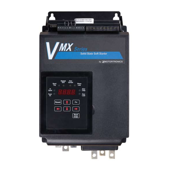
- Page 1 MO T O R T R O N I C S S o l i d S t a t e A C Mo t o r C o n t r o l V M X 2 V MX 2 S E R I E S C O MP A C T S O F T S T A R T E R B A S I C I N S T A L L A T I O N 2 0 8 - 6 0 0 V , 9 - 1 2 5 0 A mp s , 5 - 1 2 0 0 H P A N D...
-
Page 2: Table Of Contents
VMX2 Series Digital Solid State Soft Starters 18 – 1250A Basic Installation and Operation Guide Table of Contents Quick Start “Minimum Settings” Guide..................... 4 Chapter 1: Introduction ..........................5 General Description, Sizes and Ratings ......................5 Dimensions and Weights ..........................6 Chapter 2: Installation .......................... - Page 3 VMX2 Series Digital Solid State Soft Starters 18 – 1250A Basic Installation and Operation Guide Table of Contents - Continued Chapter 4: Programming ........................... 20 Introduction ..............................20 Digital Interface ............................21 Display and Program Modes ........................21 Program Function List ..........................24 Auxiliary Output Relay Settings ........................
-
Page 4: Quick Start "Minimum Settings" Guide
Basic Installation and Operation Guide Quick Startup “Minimum Settings” Guide Your new VMX2 Series Soft Starter is factory preset for a wide variety of applications and often can be used with minimal adjustment. Try these initial factory presets first and then adjust or enable the more advanced features to meet your specific starting needs. -
Page 5: Chapter 1: Introduction
Chapter 1 - Introduction General Description The VMX2 Series is a digitally programmable solid-state reduced voltage soft starter. Its six SCR design features a voltage/current ramp with an anti-oscillation circuit for smooth load acceleration. The SCRs are sized to withstand starting currents of 500% for 20 seconds (Standard Duty) and up to 500% for 60 seconds (Heavy Duty). -
Page 6: Dimensions And Weights
VMX2 Series Digital Solid State Soft Starters 18 – 1250A Basic Installation and Operation Guide Dimensions and Weights Overall Mounting Weight Enclosure Model Number A Inches B Inches C Inches D Inches E Inches F Inches (mm) (mm) (mm) (mm) -
Page 7: Chapter 2: Installation
Choosing a Location Proper location of the VMX2 Series is necessary to achieve specified performance and normal operation lifetime. The VMX2 Series should always be installed in an area where the following conditions exist: Ambient operating temperature: ... -
Page 8: Receiving, Unpacking And Inspection
Make sure there is sufficient clearance all around the unit for cooling, wiring, and maintenance purposes. To conserve panel space, the VMX2 Series - BP models were designed for close clearances of only 1 inch (25mm) on either side. A minimum clearance of 4 inches (100 mm) on the top and bottom is necessary to maximize effective airflow and cooling. -
Page 9: Electrical Connections
VMX2 Series Digital Solid State Soft Starters 18 – 1250A Basic Installation and Operation Guide Electrical Connections Power Connections Disconnect Referring to local code standards for wire sizing and length, connect power conductors to the unit input terminals marked L1, L2, L3 (R, S, Circuit T for IEC users). -
Page 10: Power Terminals
VMX2 Series Digital Solid State Soft Starters 18 – 1250A Basic Installation and Operation Guide Power Terminals: Connection points are bus tabs with pre-drilled holes (see below). Use appropriate compression or mechanical lugs for termination to these bus tabs. Suggested wire sizes and tightening torques for factory-supplied connectors for conductors rated for 75C are shown in the chart below. -
Page 11: Control Connections
Basic Installation and Operation Guide Control Connections Control connections on the VMX2 Series starter are divided into 2 groups. With the unit oriented vertically, TB1 is a 12-point DC terminal block (on the left), and TB2 is a 10-point AC terminal block (on the right side). -
Page 12: Ac Control Power Supply Connection
AC Control Power Supply Connection Separate AC Control Power supply is required to power the electronics of the VMX2 Series starter. The standard is 120VAC, but 240VAC (optional) can be ordered if necessary for your line power supply configuration. The control voltage must be connected to terminals marked A1 and A2 of TB-2 as shown in figure 4.2.1 (these... -
Page 13: Three-Wire Control Connection
A factory-installed jumper is provided which allows the VMX2 Series unit to operate if external interlocks are not used. If this jumper is removed and an interlock is not used, the VMX2 Series unit will not function. -
Page 14: Dual Ramp And Jog Features
Dual Ramp Command Closing a dry (voltage free) contact between TB1, terminals 6 and 7 will enable Ramp 2, and the VMX2 Series starter will respond to the settings for Ramp 2 in F015 - F018. If no contact closure is present, the VMX2 Series starter defaults to the Ramp 1 parameters (F011 - F014). -
Page 15: Analog Output (4-20Ma)
Basic Installation and Operation Guide Analog Output (4-20mA) The VMX2 Series starter provides a 4 to 20 milliamp output signal that can be set to monitor different parameter values using F108 and scaled with parameter F109 and F110. See section 5.6.16. -
Page 16: Fault Signal
VMX2 Series Digital Solid State Soft Starters 18 – 1250A Basic Installation and Operation Guide Fault Signal An optically isolated Triac output is dedicated as a fault indicator on TB1, terminals 11 and 12, labeled “Opto”. The output Triac switch is rated for 10 - 250VAC, 50 mA (maximum). -
Page 17: Bypass Contactor Control
No field wiring is necessary to these terminals if this feature is not used. For all other styles of VMX2 Series, the At-Speed signaling can be programmed into any of the three Output relays (section 4.2.8 and Table 5.6.9 of the user manual). - Page 18 VMX2 Series Digital Solid State Soft Starters 18 – 1250A Basic Installation and Operation Guide No field wiring is necessary to these terminals if this feature is not used. VMX2 Bypass Control Terminal Location Diagrams Bypass Control* Bypass Control* Terminals...
-
Page 19: Chapter 3: Sequence Of Operation
3. Motor should begin to slow down. Status display should begin to show decreasing motor amps. 4. When motor reaches Stop Level, VMX2 should turn off. Status display will again show [0000.] If the unit does not follow this operational sequence please contact the factory or refer to the VMX2 Series Troubleshooting Guide. -
Page 20: Chapter 4: Programming
Advanced features must be enabled via programming. The only parameter that MUST be set by the user is motor FLA (F001). Digital Interface: The VMX2 Series Soft Starter includes a digital keypad with eight LEDs, seven command keys, and an LED display with four alphanumeric digits. -
Page 21: Display And Program Modes
VMX2 Series Digital Solid State Soft Starters 18 – 1250A Basic Installation and Operation Guide Display Modes There are three modes of display: The Status Display Mode, the Program Mode, and the Fault Mode. Status Display Mode (Default Display) The Status Display Mode displays seven “screens” of information. Motor Currents (3 phases), Remaining Thermal Capacity, Ground Current, Remaining Time on the Process Timer, and Time Base of the Time Clock Controller. - Page 22 Caution! If the Fn key is pressed or power is lost before the [READ/ENTER] key is pressed, the VMX2 Series Starter will not store the selected value in memory. Fault Mode The Fault Mode Display provides information to the operator when a fault occurs and allows the operator to review fault history.
- Page 23 VMX2 Series Digital Solid State Soft Starters 18 – 1250A Basic Installation and Operation Guide Example 1: Figure 8 Entering a new FLA setting into Function 001 Viewing a Function’s Set Value [0000.] Indicates Phase A is drawing no current (unit is in Off mode).
-
Page 24: Program Function List
VMX2 Series Digital Solid State Soft Starters 18 – 1250A Basic Installation and Operation Guide Parameter Function List Motor FLA, Service Factor and Overload Protection Functions User Setting Factory Fn # Group Function Description Adjustment / Display Range Manual Increments... -
Page 25: Ol Trip
VMX2 Series Digital Solid State Soft Starters 18 – 1250A Basic Installation and Operation Guide Jog Mode Functions User Setting Factory Fn # Group Function Description Adjustment / Display Range Manual Increments Setting Section F019 Voltage Jog 5 - 100% Line Voltage 5.6.3 and... -
Page 26: Current Imbalance Trip
VMX2 Series Digital Solid State Soft Starters 18 – 1250A Basic Installation and Operation Guide Line Voltage User Setting Factory Fn # Group Function Description Adjustment / Display Range Manual Increments Setting Section F029 Voltage Input 200 - 690 Volt... - Page 27 VMX2 Series Digital Solid State Soft Starters 18 – 1250A Basic Installation and Operation Guide Lockouts, Reset and Internal Protection Functions User Setting Factory Fn # Group Function Description Adjustment / Display Range Manual Increments Setting Section Coast Down (Back Spin) Lockout...
- Page 28 VMX2 Series Digital Solid State Soft Starters 18 – 1250A Basic Installation and Operation Guide Serial Communications User Setting Factory Fn # Group Function Description Adjustment / Display Range Manual Increments Setting Section 0 = Disabled F065 Communications 1 = Enabled (11Bit)
-
Page 29: Phase Rotation Trip
VMX2 Series Digital Solid State Soft Starters 18 – 1250A Basic Installation and Operation Guide Fault History and Run Time User Setting Factory Fn # Group Function Description Adjustment / Display Range Manual Increments Setting Section 0 = No fault history, or... - Page 30 VMX2 Series Digital Solid State Soft Starters 18 – 1250A Basic Installation and Operation Guide Motor Power Protection Settings User Setting Factory Fn # Group Function Description Adjustment / Display Range Manual Increments Setting Section 0 - 2 0 = Disabled...
-
Page 31: Auxiliary Output Relay Settings
VMX2 Series Digital Solid State Soft Starters 18 – 1250A Basic Installation and Operation Guide Auxiliary Output Relay Settings Functions F060 through F062 provide the ability to program the functions of each of the 3 Output Auxiliary Relays. Factory default programming is provided which covers a wide variety of applications, but any of these relays can be changed as per the following chart. -
Page 32: Fault Mode
Basic Installation and Operation Guide Fault Mode The VMX2 Series will automatically enter the Fault Mode when a fault occurs in the motor or starter and display a code indicating the condition that caused a shutdown. Fault codes are three-digits in length and are displayed in alpha characters. -
Page 33: Chapter 5: Motor Overload Protection
By using non- volatile memory, the VMX2 Series does not “forget” that the motor has been running even if power to the starter is turned off and back on. Continuous overload protection is provided based on the true thermal condition of the motor. -
Page 34: Manual Reset
If Automatic Reset is necessary, change from Manual Reset to Automatic Reset by using Function F005. (See Section 5. of the Advanced Installation, Operation and Programming Manual for details). In this mode, a 3-wire control circuit will be capable of restart when the VMX2 Series has reset itself after the cool down period. -
Page 35: Overload Class Trip Curves
Figure 9: VMX2 Series Overload Trip Curves Overload Protection During Bypass When a Bypass Contactor is used to shunt power around the SCRs in the VMX2 Series (as in the VMX2…-BP version), overload protection is maintained as long as the VMX2 Series is directly controlling the contactor. - Page 36 MO T O R T R O N I C S S o l i d S t a t e A C Mo t o r C o n t r o l V M X 2 C o m p a c t S o f t S t a r t e r P h a s e t r o n i c s , I n c .
Need help?
Do you have a question about the VMX2 SERIES and is the answer not in the manual?
Questions and answers