Table of Contents
Advertisement
Quick Links
Advertisement
Table of Contents

Related Manuals for motortronics VMX-18-BP


Summary of Contents for motortronics VMX-18-BP
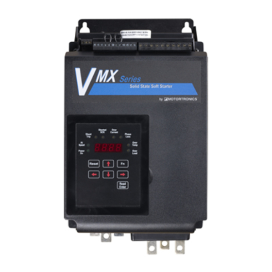
- Page 1 MOTORTRONICS Solid State AC Motor Control VMX Series Digital Solid State Soft Starter 18 – 1000A Basic Installation and Quick Startup Guide Document #VMX-QSG604132MN Firmware Revision 3.01 Phone: 800.894.0412 - Fax: 888.723.4773 - Web: www.clrwtr.com - Email: info@clrwtr.com...
- Page 2 Basic Installation and Operation Guide VMX Series Digital Solid State Soft Starters 18 – 1000A Page 2 of 27 Phone: 800.894.0412 - Fax: 888.723.4773 - Web: www.clrwtr.com - Email: info@clrwtr.com...
-
Page 3: Table Of Contents
Basic Installation and Operation Guide VMX Series Digital Solid State Soft Starters 18 – 1000A Table of Contents VMX Series Digital Solid State Soft Starter 18 – 1000A Quick Start “Minimum Settings” Guide Chapter 1: Introduction General Description, Sizes and Ratings ……… Dimensions ……………………………………..…... - Page 4 Basic Installation and Operation Guide VMX Series Digital Solid State Soft Starters 18 – 1000A Page 4 of 27 Phone: 800.894.0412 - Fax: 888.723.4773 - Web: www.clrwtr.com - Email: info@clrwtr.com...
-
Page 5: Quick Start "Minimum Settings" Guide
Basic Installation and Operation Guide VMX Series Digital Solid State Soft Starters 18 – 1000A Quick Startup “Minimum Settings” Guide Your new VMX Series Soft Starter is factory preset for a wide variety of applications and often can be used with minimal adjustment. -
Page 6: Chapter 1: Introduction
It requires 120VAC (220VAC optional) control power and uses dry contact inputs for Start / Stop control. Programmable auxiliary contacts and provisions for interlocking are also included. Sizes and Ratings The Motortronics VMX Series starters are current rated controllers. Max. Amp Model Current ratings are for continuous duty and must not be exceeded. -
Page 7: Dimensions
Basic Installation and Operation Guide VMX Series Digital Solid State Soft Starters 18 – 1000A Dimensions Overall Mounting Enclosure Model Number VMX -18-BP through 8.00 8.00 6.68 7.63 6.75 0.22 VMX -48-BP VMX -62-BP through 13.50 8.00 6.68 12.75 6.75 0.38 VMX -112-BP VMX -150-BP and... -
Page 8: Chapter 2 - Installation
Basic Installation and Operation Guide VMX Series Digital Solid State Soft Starters 18 – 1000A Chapter 2 - Installation Receiving and Unpacking Upon receipt of the product, you should immediately do the following: Carefully unpack the unit from the shipping carton and inspect it for shipping damage (if damaged, notify the freight carrier and file a claim within 15 days of receipt). -
Page 9: Mounting Clearances And Cleaning
Basic Installation and Operation Guide VMX Series Digital Solid State Soft Starters 18 – 1000A Clearances When mounting into an enclosure, make sure there is sufficient clearance all around the unit for cooling, wiring and maintenance purposes. To conserve panel space, the VMX Series –BP models were designed for close horizontal clearances of only 1 inch (25mm) on either side. -
Page 10: Power Connection And Terminations
Basic Installation and Operation Guide VMX Series Digital Solid State Soft Starters 18 – 1000A Electrical connections Power Terminations All line and load power terminations are to be made to plated copper Bus Tabs located on each unit. Bus tabs are pre-drilled to accept industry standard bolts. - Page 11 Model Range Wire Size Torque Size Torque Wire Size Min.- Max. in.-lbs. ISOmm Number VMX-18-BP 9 - 18 0.22” hole (5.58mm) for VMX-28-BP 14 - 28 #10 (or M5) screw / nut / VMX-39-BP 19 - 39 lock washer (not included)
-
Page 12: Control Power Requirements
Basic Installation and Operation Guide VMX Series Digital Solid State Soft Starters 18 – 1000A Control Connections Control connections on the VMX Series starter are divided into 2 groups. With the unit oriented vertically, TB1 is a 12 point DC terminal block (on the left), and TB2 is a 10 point AC terminal block (on the right side). These are removable terminal blocks for ease of connection and servicing, and are provided with different spacing (pitch) between the header pins so they are not interchangeable. - Page 13 Basic Installation and Operation Guide VMX Series Digital Solid State Soft Starters 18 – 1000A Control Fusing Output relays in TB2 must be protected from currents in excess of 5A, either with a fuse or with other suitable current protection devices. A dedicated fault output for use in PLC or interposing relay control is available on TB1.
- Page 14 Basic Installation and Operation Guide VMX Series Digital Solid State Soft Starters 18 – 1000A PTC Thermistor Input The VMX Series starter is provided with input terminals for connecting a PTC (Positive Temperature Coefficient) Thermistor that may be imbedded in the motor. These are specialized resistors imbedded in some motor windings that increase resistance as the temperature increases.
- Page 15 Dry relay output contacts from three programmable auxiliary relays are available on TB2. Outputs #1 and #2 are Form C (SPDT), with a Common, N.O. and N.C. Output #3 is a Form A, (SPST), N.O. contact. Motortronics recommends fusing all contacts with external fuses.
-
Page 16: Chapter 3 - Sequence Of Operation
Basic Installation and Operation Guide VMX Series Digital Solid State Soft Starters 18 – 1000A Chapter 3 - Sequence of Operation Starting: 1. Apply three phase power to the unit. The motor should not run until a Start command is applied. 2. -
Page 17: Chapter 4 - Programming
Basic Installation and Operation Guide VMX Series Digital Solid State Soft Starters 18 – 1000A Chapter 4 - Programming It is best to operate the motor at its full load starting conditions to achieve the proper time, torque and ramp settings. -
Page 18: Display And Program Modes
Basic Installation and Operation Guide VMX Series Digital Solid State Soft Starters 18 – 1000A Display Modes: There are three modes of display: the Status Display Mode, the Program Mode, and the Fault Mode. Status Display Mode (Default Display) The Status Display Mode displays seven “screens” of information. Motor Currents (3 phases), Remaining Thermal Capacity, Ground Current, Remaining Time on the Process Timer, and Time Base of the Time Clock Controller. - Page 19 Basic Installation and Operation Guide VMX Series Digital Solid State Soft Starters 18 – 1000A Example 1: Figure 14 Entering a new FLA setting into Funtion 1 [0000.] Indicates Phase A is drawing no current Example 1: Setting the Motor FLA (unit is in Off mode).
-
Page 20: Program Function List
Basic Installation and Operation Guide VMX Series Digital Solid State Soft Starters 18 – 1000A VMX Series Basic Start-up Parameters and Factory Defaults Setting Factory Fn # Function Description Adjustment / Display Range Increments Setting Motor Nameplate FLA 50-100% of Max Amp Rating. F001 FLA must be programmed for Upper limit of range automatically adjusts downward as Service... - Page 21 Basic Installation and Operation Guide VMX Series Digital Solid State Soft Starters 18 – 1000A Setting Factory Fn # Function Description Adjustment / Display Range Increments Setting F030 See Advanced Installation, Operation and Programming Manual, Process Timer Functions thru Appendix 4 for details. F039 These features are disabled from factory.
- Page 22 Basic Installation and Operation Guide VMX Series Digital Solid State Soft Starters 18 – 1000A Setting Factory Fn # Function Description Adjustment / Display Range Increments Setting F075 Real Time Clock - Year 2000 - 2047 1 year 2000 F076 Real Time Clock - Month 1 - 12 1 Month...
- Page 23 Basic Installation and Operation Guide VMX Series Digital Solid State Soft Starters 18 – 1000A Aux. (Output) Relay Settings Functions F060 through F062 provide the ability to program the functions of each of the 3 Output Auxiliary Relays. Factory default programming is provided which covers a wide variety of applications, but any of these relays can be changed as per the following chart.
-
Page 24: Fault Mode
Basic Installation and Operation Guide VMX Series Digital Solid State Soft Starters 18 – 1000A Fault Mode The VMX Series will automatically enter the Fault Mode when a fault occurs in the motor or starter and display a code indicating the condition that caused a shutdown. Fault codes are three-digits in length and are displayed in alpha characters. -
Page 25: Chapter 5 - Motor Overload Protection
Basic Installation and Operation Guide VMX Series Digital Solid State Soft Starters 18 – 1000A Chapter 5 - Motor Overload Protection Solid State Overload Protection The VMX Series Starter provides true U.L. listed I t Thermal Overload Protection as a built-in function of the main digital processor for maximum motor protection. - Page 26 Basic Installation and Operation Guide VMX Series Digital Solid State Soft Starters 18 – 1000A Manual Reset The factory default setting is Manual Reset. This means that when the Overload Trip is activated, the starter cannot be restarted without pressing the Reset key. The Overload Trip will not reset until the motor cools down (see 3.1.3.d).
-
Page 27: Overload Class Trip Curves
Basic Installation and Operation Guide VMX Series Digital Solid State Soft Starters 18 – 1000A Overload Trip Curve Chart Figure 15: VMX Series Overload Trip Curves Overload Protection During Bypass When a Bypass Contactor is used to shunt power around the SCRs in the VMX Series (as in the VMX…-BP version), overload protection is maintained as long as the VMX Series is directly controlling the contactor.
Need help?
Do you have a question about the VMX-18-BP and is the answer not in the manual?
Questions and answers