
Related Manuals for motortronics VMX Series


Summary of Contents for motortronics VMX Series
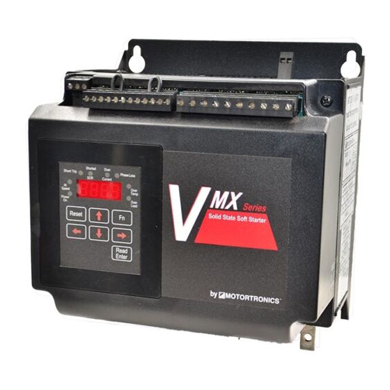
- Page 1 MO T O R T R O N I C S S o l i d S t a t e A C Mo t o r C o n t r o l V M X S e r i e s C o m p a c t S o f t S t a r t e r R a t i n g s 1 8 - 1 2 5 0 A B A S I C I N S T A L L A T I O N...
-
Page 2: Table Of Contents
VMX Series Digital Solid State Soft Starters 18 – 1250A Basic Installation and Operation Guide Table of Contents Quick Start “Minimum Settings” Guide ....................4 Chapter 1: Introduction ..........................5 General Description, Sizes and Ratings ....................... 5 Dimensions and Weights ..........................6 Chapter 2: Installation .......................... - Page 3 VMX Series Digital Solid State Soft Starters 18 – 1250A Basic Installation and Operation Guide Table of Contents - Continued Chapter 4: Programming ......................... 18 Introduction ............................... 18 Digital Interface ............................18 Display and Program Modes ........................18 Program Function List ..........................22 Auxiliary Output Relay Settings .........................
-
Page 4: Quick Start "Minimum Settings" Guide
Basic Installation and Operation Guide Quick Startup “Minimum Settings” Guide Your new VMX Series Soft Starter is factory preset for a wide variety of applications and often can be used with minimal adjustment. Try these initial factory presets first and then adjust or enable the more advanced features to meet your specific starting needs. -
Page 5: Chapter 1: Introduction
Chapter 1 - Introduction General Description The VMX Series is a digitally programmable solid state reduced voltage soft starter using a six SCR design. It features a voltage/current ramp for smooth load acceleration. The SCRs are sized to withstand starting currents of 350% for 30 seconds and up to 600% for 10 seconds for applications typical to NEMA / UL Class 10 overload trip curves. -
Page 6: Dimensions And Weights
VMX Series Digital Solid State Soft Starters 18 – 1250A Basic Installation and Operation Guide Dimensions and Weights Overall Mounting Weight Enclosure Model Number A Inches B Inches C Inches D Inches E Inches F Inches (mm) (mm) (mm) (mm) -
Page 7: Chapter 2: Installation
(FLC or FLA) rating and Service Factor (if used). Choosing a Location Proper location of the VMX Series is necessary to achieve specified performance and normal operation lifetime. The VMX Series should always be installed in an area where the following conditions exist: Ambient operating temperature: •... -
Page 8: Receiving, Unpacking And Inspection
Make sure there is sufficient clearance all around the unit for cooling, wiring and maintenance purposes. To conserve panel space, the VMX Series – BP models were designed for close vertical clearances of only 1 inch (25mm) on either side. A minimum horizontal clearance of 4” (100 mm) on the top and bottom is necessary to maximize effective airflow and cooling. -
Page 9: Electrical Connections
VMX Series Digital Solid State Soft Starters 18 – 1250A Basic Installation and Operation Guide Electrical Connections Power Connections Disconnect Referring to local code standards for wire sizing and length, connect power conductors to the unit input terminals marked L1, L2, L3 (R, S, Circuit T for IEC users). -
Page 10: Power Terminals
503 - 1006 VMX-1250-BP 625 - 1250 Table 3: VMX Series Wire Ranges and Torque Specifications Note: TBD = To Be Determined at a later date Remote Keypad Mounting The keypad / operator interface unit can be remotely mounted up to 10’ (3 meters) away from the starter, i.e. -
Page 11: Control Connections
Control Connections Control connections on the VMX Series starter are divided into 2 groups. With the unit oriented vertically, TB1 is a 12-point DC terminal block (on the left), and TB2 is a 10 point AC terminal block (on the right side). These are removable terminal blocks for ease of connection and servicing, and are provided with different spacing (pitch) between the header pins so they are not interchangeable. -
Page 12: Control Fusing
CAUTION! Control Terminals 1-10 of TB1 are configured using solid state devices powered internally with a 24VDC power supply. To prevent damage to the VMX Series control board, use dry (unpowered) contact closures only when connecting to these terminals. If existing 120VAC or other powered control circuit must be interfaced, use isolating relays and control the VMX Series with 2 wire control as shown above. -
Page 13: Ptc Thermistor Input
Basic Installation and Operation Guide PTC Thermistor Input The VMX Series starter is provided with input terminals for connecting a PTC (Positive Temperature Coefficient) Thermistor that may be imbedded in the motor. These are specialized resistors imbedded in some motor windings that increase in resistance as the temperature increases. -
Page 14: Dual Ramp And Jog Features
Dual Ramp Command Closing a dry (voltage free) contact between TB1, terminals 6 and 7 will enable Ramp 2, and the VMX Series starter will respond to the settings for Ramp 2 in F015 - F018. If no contact closure is present, the VMX Series starter defaults to the Ramp 1 parameters (F011 –... -
Page 15: Output (Auxiliary) Relay Contacts
Output (Auxiliary) Relay Contacts Three programmable auxiliary relays are on TB2. The VMX Series starter comes with three programmable dry relay output contacts. Outputs 1 and 2 are Form C (SPDT), with a Common, N.O. and N.C. Output 3 is a Form A, (SPST), N.O. - Page 16 VMX Series Digital Solid State Soft Starters 18 – 1250A Basic Installation and Operation Guide No field wiring is necessary to these terminals if this feature is not used. Independent Independent Bypass Control Bypass Control Terminals 18 - 160A Units Terminals: 210 –...
-
Page 17: Chapter 3: Sequence Of Operation
3. Motor should begin to slow down. Status display should begin to show decreasing motor amps. 4. When motor reaches Stop Level, VMX should turn off. Status display will again show [0000.] If the unit does not follow this operational sequence please contact the factory or refer to the VMX Series Troubleshooting Guide. -
Page 18: Chapter 4: Programming
Advanced features must be enabled via programming. The only parameter that MUST be set by the user is motor FLA (F001). Digital Interface: The VMX Series Soft Starter includes a digital keypad with eight LEDs, seven command keys, and an LED display with four alphanumeric digits. - Page 19 VMX Series Digital Solid State Soft Starters 18 – 1250A Basic Installation and Operation Guide Display Modes There are three modes of display: The Status Display Mode, the Program Mode, and the Fault Mode. Status Display Mode (Default Display) The Status Display Mode displays seven “screens” of information. Motor Currents (3 phases), Remaining Thermal Capacity, Ground Current, Remaining Time on the Process Timer, and Time Base of the Time Clock Controller.
- Page 20 VMX Series Digital Solid State Soft Starters 18 – 1250A Basic Installation and Operation Guide Changing a Function’s Set Value From the instructions above, after pressing the [READ/ENTER] key the display will show the value of that function with one digit flashing (usually the rightmost digit). Flashing indicates this is the digit to be altered (similar to cursor position).
- Page 21 VMX Series Digital Solid State Soft Starters 18 – 1250A Basic Installation and Operation Guide Example 1: Figure Entering a new FLA setting into Function Viewing a Function’s Set Value [0000.] Indicates Phase A is drawing no current (unit is in Off mode).
-
Page 22: Program Function List
VMX Series Digital Solid State Soft Starters 18 – 1250A Basic Installation and Operation Guide Program Function List Setting Factory Fn # Group Function Description Adjustment / Display Range Setting Increments Setting 50-100% of Max Amp Rating. Motor Nameplate FLA... - Page 23 VMX Series Digital Solid State Soft Starters 18 – 1250A Basic Installation and Operation Guide Setting Factory Fn # Group Function Description Adjustment / Display Range Setting Increments Setting 0 = Disabled (coast to stop) Pump-Flex Control / 1 = Enabled, except after OL trip...
- Page 24 VMX Series Digital Solid State Soft Starters 18 – 1250A Basic Installation and Operation Guide Setting Factory Fn # Group Function Description Adjustment / Display Range Setting Increments Setting 0 = Disabled, or F040 Current Imbalance Trip 0 Disabled 5 - 30% imbalance...
- Page 25 VMX Series Digital Solid State Soft Starters 18 – 1250A Basic Installation and Operation Guide Setting Factory Fn # Group Function Description Adjustment / Display Range Setting Increments Setting 0 = Disabled F065 Communications 1 = Enabled (11Bit) 2 = Enabled (10Bit)
- Page 26 10K overflow Function 51 Internal protection features Several protection features in the VMX Series are accomplished with internal hardware and use software switches in Function 51 to enable or disable them. The following chart shows these functions and the factory default settings. Refer to the Advanced Installation, Operation and Programming Manual, Section 5.6.8.a for details on how to change these settings.
-
Page 27: Auxiliary Output Relay Settings
VMX Series Digital Solid State Soft Starters 18 – 1250A Basic Installation and Operation Guide Auxiliary Output Relay Settings Functions F060 through F062 provide the ability to program the functions of each of the 3 Output Auxiliary Relays. Factory default programming is provided which covers a wide variety of applications, but any of these relays can be changed as per the following chart. -
Page 28: Fault Mode
Basic Installation and Operation Guide Fault Mode The VMX Series will automatically enter the Fault Mode when a fault occurs in the motor or starter and display a code indicating the condition that caused a shutdown. Fault codes are three-digits in length and are displayed in alpha characters. -
Page 29: Chapter 5: Motor Overload Protection
By using non- volatile memory, the VMX Series does not “forget” that the motor has been running even if power to the starter is turned off and back on. Continuous overload protection is provided based on the true thermal condition of the motor. - Page 30 If Automatic Reset is necessary, change from Manual Reset to Automatic Reset by using Function F005. (See Section 5. of the Advanced Installation, Operation and Programming Manual for details). In this mode, a 3-wire control circuit will be capable of restart when the VMX Series has reset itself after the cool down period.
-
Page 31: Overload Class Trip Curves
Overload Protection During Bypass When a Bypass Contactor is used to shunt power around the SCRs in the VMX Series (as in the VMX…- BP version), overload protection is maintained as long as the VMX Series is directly controlling the contactor. - Page 32 MO T O R T R O N I C S S o l i d S t a t e A C Mo t o r C o n t r o l V M X S e r i e s C o m p a c t S o f t S t a r t e r P h a s e t r o n i c s I n c .
Need help?
Do you have a question about the VMX Series and is the answer not in the manual?
Questions and answers