Sign In
Upload
Manuals
Brands
Moons' Manuals
Servo Drives
M2DC Series
User Manuals: Moons' M2DC Series Servo Drives
Manuals and User Guides for Moons' M2DC Series Servo Drives. We have
1
Moons' M2DC Series Servo Drives manual available for free PDF download: Hardware Manual
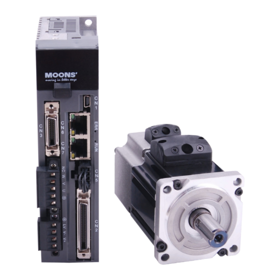
Moons' M2DC Series Hardware Manual (168 pages)
DC Servo System
Brand:
Moons'
| Category:
Servo Drives
| Size: 6 MB
Table of Contents
Table of Contents
2
Introduction
8
About this Manual
8
Documentation Set for the M2DC Series Servo Drive
8
Safety
8
Safety Symbols
8
Safety Instructions
9
Guideline for Parts Replacement
9
Parts Replacement
9
Bearing Life
10
Standards Compliance
11
Product Description
12
System Checklist
12
Servo Drive Model Introduction
12
Drive Name Plate Description
12
Drive Model Description
12
Drive Specifications
13
Drive Dimensions (Unit: MM)
14
M2Dc-20D
14
Servo Motor Model Introduction
15
Motor Name Plate Description
15
Motor Model Description
15
Motor Specifications and Dimensions
16
40Mm Specifications and Dimensions
16
60Mm Specifications and Dimensions
18
80Mm Specifications and Dimensions
20
Servo Drive and Servo Motor Combinations
23
Installation
24
Storage Conditions
24
Installation Conditions
24
Installation Space
25
Motor Installation
26
Connections and Wiring
27
Connecting to Peripheral Devices
27
System Configuration
27
Servo Drive Connectors and Terminals
28
Connections and Wiring Notes
28
Wiring Methods for P1 Power Supply Connector
29
Wiring to the P2 Connector
30
Motor Power Cable Configuration
30
Motor Power Cable Connector(-CD Winding ,6Amps)
30
PIN Assignment
30
Motor Connector Specifications
30
Motor Extension Cable Wiring Diagram
31
Motor Power Cable Connector(-CF Winding,10 and 20Amps)
31
PIN Assignment
31
Motor Extension Cable Wiring Diagram
32
Encoder Connector CN3
33
Motor Encoder Feedback Cable Configuration
33
Layout of CN3 Connector
33
Connection to Motor Encoder
34
Specifications of Encoder Connector
34
Motor Encoder Extension Cable Wiring Diagram
35
STO Connector
36
Safety Precautions
36
STO Input/Output Signals
36
STO Internal Circuit Diagram
36
CN5 Connector Diagram
36
STO Signal Definition
37
STO Connection Diagrams
37
Electromagnetic Brake
38
Wiring Diagram
38
Brake Motor
38
Timing Charts of the Electromagnetic Brake
38
Regeneration Resistor
39
Recommended External Resistor
39
Regeneration Resistorconfiguration
39
Recommended Cable Specifications
40
Connecting to the Host Computer - CN1
40
Input and Output Signal Interface Connector - CN2
40
Input and Output Interface Specifications and Diagram
40
Signal Description of Connector CN2
41
Layout of CN2 Connector
42
Input Signals
42
Input Function List
43
Output Signals
44
Output Function List
44
Input Signal Interface Connector, CN2
45
Position Pulse Signal Input
45
Analog Signal Input for Velocity and Torque Mode
46
High Speed Input Ports X1, X2, X3, X4
47
General Digital Input X5, X6, X7, X8
49
X9, X10, X11, X12 Inputs with Common COM Port
51
CN2 Output Signal Specification
52
Encoder Feedback Output
53
A/B/Z Connection Diagram
53
Z Phase Open Collector Output
53
Display and Operation
54
Control Panel Description
54
Mode Switch Control
55
LED Display Description
56
Decimal Point and Negative Sign Description
56
Parameter View Setting
56
Parameter Save Setting
56
Point to Point Motion Mode
57
Jog Mode
57
Control Panel Lock
57
Status Monitoring Selection Mode
58
Function Control Mode
60
Function Mode Description
60
Operation Flow Chart
61
Parameter Setting Mode
62
Parameter Setting Description
62
Parameter Editing Examples
63
Control Panel Lock
64
Warning and Fault Display
64
Preoperational Mode
66
Inspection before Trial Run
66
Trial Run Procedure
66
Motor Configuration
67
Using the Drive Control Panel for Configuration
67
Using M Servo Suite Software for Configuration
68
Operations of JOG Mode
69
Configuration by Personal Computer
70
Operation Mode Selection
71
General Function Settings
71
Drive Servo on Settings
71
Alarm Reset
72
CW/CCW Limit
73
Global Gain Selection
74
Control Mode Selection
75
Drive on Fault Output
76
Motor Brake Control
77
Servo Ready Output
78
Position Mode
79
Digital Pulse Position Mode Connection Diagram
79
Input Pulse Type and Input Noise Filter
80
Control Pulse Dividing Switch
82
Pulse Inhibit
83
Electronic Gearing Ratio
84
Jerk Smoothing Filter
85
In-Position Error Output
85
Gain Parameters for Position Control Mode
86
Software Configuration for Position Mode
87
Velocity Mode
88
Velocity Mode Connection Diagram
89
Parameter Settings for Analog Velocity Control Mode
90
Basic Settings for Analog Velocity Control Mode
91
Analog Input Filter
96
Software Configuration for Analog Velocity Mode
97
Torque Mode
98
Analog Torque Mode Connection Diagram
99
Parameters for Analog Torque Mode
100
Basic Settings for Analog Torque Mode
101
Software Configuration for Analog Torque Mode
106
Position Table Mode
107
Linear Motion
107
Linear Motion Software Configuration
107
Basic Configuration
108
Homing Settings
109
Print
109
Position Definition
109
Simulate
110
Linear Motion Input Definition
110
Rotary Motion
111
Rotary Motion Software Configuration
111
Rotary Motion Input Definition
112
Parameters and Functions
113
Parameter Category
113
Parameter List
113
Parameter Description
118
Communication
140
What Is SCL
140
Connections
140
PIN Definition
140
Connection Method
141
Modbus/Rtu Communication
142
Data Encoding
142
Communication Address
142
Communication Baud Rate and Framing
142
Power up Mode
143
M2DC Series Servo Drive Register Addresses and Function List
143
Command Opcode Description
151
Function Code
153
Modbus/Rtu Applications
156
Canopen Communication
162
RJ45 (8P8C) Pin Definitions
162
Canopen NODE-ID
162
Canopen Communication Baud Rate
162
Trouble Shooting
163
Drive Alarm List
163
Appendix
166
Appendix 1: LED Character Reference
166
Appendix 2: Cables and Connectors
166
Advertisement
Advertisement
Related Products
MOONS’ M2DC-6D0
MOONS’ M2DC-10D
Moons' M2DC-6D05S
Moons' M2DC-10D5S
Moons' M2DC-20D5S
Moons' M2DC-6D05Q
Moons' M2DC-10D5Q
Moons' M2DC-20D5Q
Moons' M2DC-6D05R
Moons' M2DC-10D5R
Moons' Categories
Servo Drives
DC Drives
Engine
Control Unit
Controller
More Moons' Manuals
Login
Sign In
OR
Sign in with Facebook
Sign in with Google
Upload manual
Upload from disk
Upload from URL